
Fuse box diagrams, fuse layouts and assignment

Ford Excursion (1999-2005) Fuse Diagram
Advertisements
Fuse box diagram (fuse layout), location and assignment of fuses and relays Ford Excursion (1999, 2000, 2001, 2002, 2003, 2004, 2005).

Checking and Replacing Fuses
Fuses and circuit breakers protect your vehicle’s electrical system from overloading. If electrical parts in your vehicle are not working, the system may have been overloaded and blown a fuse or tripped a circuit breaker. Before you replace or repair any electrical parts, check the appropriate fuses or circuit breakers.
To check a fuse, look at the silver-colored band inside the fuse. If the band is broken or melted, replace the fuse.
- Before replacing fuses check that the key has been removed from the ignition and that all the services are switched off and/or disengaged.
- Always disconnect the battery before servicing high current fuses.
- Always replace a fuse with one that has the specified amperage rating. Using a fuse with a higher amperage rating can cause severe wire damage and could start a fire.
- Never replace a broken fuse with anything other than a new fuse. Use always an intact fuse of the same color.
- If a fuse blows again contact a qualified service center.
Passenger Compartment Fuse Box
The fuse panel is located below and to the left of the steering wheel by the brake pedal. To remove the fuse panel cover, turn the panel fasteners counterclockwise.

Diagram 1999-2001

Diagram 2002-2005

Engine Compartment Fuse Box
The power distribution box is located in the engine compartment.


- Ford Manuals
- 2004 Excursion
- Owner's manual
Ford 2004 Excursion Owner's Manual
- Workshop manual (19 pages)
- page of 265 Go / 265
Table of Contents
Introduction.
- Safety and Environment Protection
- Warning Symbols in this Guide
- Warning Symbols on Your Vehicle
- Breaking-In
- Service Data Recording
- Event Data Recording
- Notice to Owners of Diesel-Powered Vehicles
- Notice to Owners of Pickup Trucks and Utility Type Vehicles
- Snowplowing
- Middle East/North Africa Vehicle Specific Information
- Vehicle Symbol Glossary
Instrument Cluster
- Service Engine Soon Light
- Check Fuel Cap Light
- Check Gage Light
- Brake System Warning Light
- Anti-Lock Brake System Light
- Air Bag Readiness Light
- Safety Belt Light
- Low Fuel Light
- Speed Control Light
- Four Wheel Drive Light
- Door Ajar Light
- Key-In-Ignition Warning Chime
- Headlamps on Warning Chime
- Speedometer
- Engine Coolant Temperature Gauge
- Odometer, Trip Odometer
- Engine Oil Pressure Gauge
- Transmission Fluid Temperature Gauge
- White Area (Normal)
- Yellow Area (Warning)
- Red Area (over Temperature)
Entertainment Systems
- Power/Volume
- Premium AM/FM Stereo/Cassette/Single CD
- Dolby Noise Reduction
- Fast Forward
- Premium In-Dash Six CD Sound System
- Compression
- FIND Program Type
- Seamless Play
- Setting the Clock
- Rear Audio Controls
- Cassette/Player Care
- Radio Frequencies
- Radio Reception Factors
- CD/CD Player Care
- Rear Seat Entertainment DVD System
- DVD Player Controls
- DVD Control Features
- CD Play Mode, Slow Play Mode
- Enter Control
- Next/Previous Control
- REV/FWD Control
- Remote Control
- User Menu Mode
- Battery Replacement (Remote Control)
- Adjusting the Volume from the Rear Seat Controls
- Mode Select
- Rear Seat Controls
- Memory Preset Control
- Seek Function
- Parental Control
- Using Wired Headphones/Personal Audio Feature
- Wireless Headphone Operation
- Wireless Headphones (for DVD System Only)
- Liquid Crystal Display (LCD) Flip-Down Screen
- General Operating Tips (Entertainment System)
- High Temperature Sensor Circuit
- Playback and Format
- Rear Seat Entertainment DVD System Protection Circuits
- Inserting a CD/DVD
- Playing a Video Game/Auxiliary Device
- Removing a CD/DVD
- On-Screen Indicators
- Safety Information
- Care and Service of the DVD Player
- Cleaning Compact Discs
- Cleaning the DVD Player
- Cleaning the Liquid Crystal Display (LCD) Flip-Down Screen
- Foreign Substances Entering DVD Player
Climate Controls
- Heater Only System
- Manual Heating and Air Conditioning System
- Electronic Automatic Temperature Control (EATC) System
- Auxiliary System
- Front Auxiliary Controls
- Rear Auxiliary Controls
- Rear Window Defroster
- Autolamp Control
- Headlight Control
- Daytime Running Lamps (DRL)
- Foglamp Control
- Aiming the Headlamp
- Flash to Pass
- Panel Dimmer Control
- Dome/Map Lamps
- Interior Lamps
- Rear Courtesy/Reading Lamps
- Rear Dome Lamp
- Replacing Exterior Bulbs
- Using the Right Bulbs
- Replacing Front Parking/Turn Signal Bulbs
- Replacing Headlamp Bulbs
- Replacing Foglamp Bulbs
- Replacing Tail Lamp/Turn/Backup Lamp Bulbs
- Replacing High-Mount Brakelamp Bulbs
- Replacing License Plate Lamp Bulbs
Driver Controls
- Multi-Function Lever
- Rear Window Wiper/Washer Controls
- Windshield Wiper/Washer Control
- Changing the Wiper Blades
- Tilt Steering Wheel
- (4–Speed Automatic Transmission)
- (5–Speed Automatic Transmission)
- Tow/Haul Feature
- Transmission Control
- Forward Storage bin
- Illuminated Visor Mirror
- Installing a Garage Door Opener
- Overhead Console
- Auxiliary Power Point
- Power Quarter Rear Windows
- Automatic Dimming Inside Rear View Mirror
- Window Lock
- Heated Outside Mirrors
- Power Side View Mirrors
- Mirror Mounted Side Turn Signal Indicator
- Clearance Lamps
- Fold-Away Mirrors
- Power Adjustable Foot Pedals
- Increasing Speed While Using Speed Control
- Resuming a Set Speed
- Indicator Light
- Reducing Speed While Using Speed Control
- Turning off Speed Control
- Climate Control Features
- Radio Control Features
- Steering Wheel Controls
- Trip Computer
- Average Fuel Economy
- English/Metric Display
- Mode Control
- Selectable Features
- Outside Air Temperature
- Compass Calibration Adjustment
- Compass Zone Adjustment
- Homelink Wireless Control System
- Programming
- Gate Operator & Canadian Programming
- Erasing Homelink Buttons
- Operating the Homelink Wireless Control System
- Reprogramming a Single Homelink Button
- Cell Phone Use
- Center Console
- Luggage Rack
Locks and Security
- Power Door Locks
- Smart Locks
- Childproof Door Locks
- Remote Entry System
- Unlocking the Doors
- Locking the Doors
- Power Door Lock Disable Feature
- Sounding a Panic Alarm
- Replacing the Battery in the Remote Entry Transmitter
- Replacing Lost Remote Entry Transmitters
- How to Reprogram Your Remote Entry Transmitters
- Illuminated Entry
- Keyless Entry System
- Programming a Personal Entry Code
- Erasing Personal Code
- Anti-Scan Feature
- Unlocking and Locking the Doors Using Keyless Entry
- To Deactivate/Reactivate the Autolock Feature Using the Keypad
- To Deactivate/Reactivate the Autolock Feature Using the Power Door Unlock Control
- Securilock Passive Anti-Theft System
- Theft Indicator
- Automatic Arming
- Automatic Disarming
- Replacement Keys
- Programming Spare Keys
- 40/20/40 Seat
Seating and Safety Restraints
- 60/40 Split Bench Seat
- Captain’s Chair
- Memory Seats and Adjustable Pedals
- Using the Manual Lumbar Support
- Adjusting the Front Power Seat
- Heated Seats
- 40/20/40 Front Seat Armrest and Console
- Folding down Rear Seats into Load Floor
- Head Restraints
- Returning the Seat to Upright
- Accessing the Third Row Seat
- Reclining the Second Row Seatback
- Third Row Seat
- Folding down the Third Row Seat
- Removing the Third Row Seat
- Installing the Third Row Seat
- Automatic Locking Mode
- Combination Lap and Shoulder Belts
- Vehicle Sensitive Mode
- How to Disengage the Automatic Locking Mode
- How to Use the Automatic Locking Mode
- Energy Management Feature
- Safety Belt Replacement Label
- Front and Second Row Outboard Safety Belt Height Adjustment
- Adjusting the Lap Belt
- Safety Belt Warning Light and Indicator Chime
- Reasons most Often Given for Not Wearing Safety Belts
- Deactivating/Activating the Beltminder Feature
- One Time Disable (Beltminder)
- Safety Belt Extension Assembly
- Safety Belt Maintenance
- Air Bag Supplemental Restraint System (SRS)
- Important SRS Precautions
- Children and Air Bags
- How Does the Air Bag Supplemental Restraint System Work?
- Determining if the System Is Operational
- Disposal of Air Bags and Air Bag Equipped Vehicles (Including Pretensioners)
- Important Child Restraint Precautions
- Safety Restraints for Children
- Child Booster Seats
- Children and Safety Belts
- When Children Should Use Booster Seats
- Types of Booster Seats
- Child and Infant or Child Safety Seats
- Safety Seats for Children
- The Importance of Shoulder Belts
- Installing Child Safety Seats with Combination Lap and Shoulder Belts
- Attaching Child Safety Seats with Tether Straps
- Positions of the Ignition
- Preparing to Start Your Vehicle
- Important Safety Precautions
- Starting the Engine
- Using the Engine Block Heater
- Guarding against Exhaust Fumes
- Important Ventilating Information
- Four-Wheel Anti-Lock Brake System (ABS)
- ABS Warning Lamp
- Parking Brake
- Traction-Lok Axle
- Preparing to Drive Your Vehicle
- Automatic Transmission Operation
- Brake-Shift Interlock
- R (Reverse)
- N (Neutral)
- D Overdrive
- Forced Downshifts
- Shift Strategy
- Understanding the Shift Positions of the 5–Speed Automatic Transmission (if Equipped - Diesel Engines Only)
- If Your Vehicle Gets Stuck in Mud or Snow
- Reverse Sensing System (RSS)
- Four–Wheel Drive (4WD) Operation
- Electronic Shift on the Fly (ESOF) 4X4 System
- 4WD System Indicator Lights
- Using the Electronic Shift 4WD System
- Positions of the Electronic Shift System
- 2H (2WD High) – for General On-Road Driving
- 4H (4WD High)/4L (4WD Low)
- Shifting from 2WD (2WD High) to 4X4 HIGH (4WD High)
- Shifting from 4X4 HIGH (4WD High) to 2WD (2WD High)
- Shifting from 4X4 HIGH (4WD High) to 4X4 LOW (4WD Low)
- Shifting from 4X4 LOW (4WD Low) to 4X4 HIGH (4WD High) or 2WD (2WD High)
- Driving Off-Road with Truck and Utility Vehicles
- How Your Vehicle Differs from Other Vehicles
- Basic Operating Principles
- If Your Vehicle Goes off the Edge of the Pavement
- If Your Vehicle Gets Stuck
- Emergency Maneuvers
- 4WD Systems
- Mud and Water Driving
- Normal Characteristics
- Driving on Hilly or Sloping Terrain
- Driving on Snow and Ice
- Tires, Replacement Requirements
- Maintenance and Modifications
- Driving through Water
- Vehicle Loading - with and Without a Trailer
- Base Curb Weight
- Vehicle Curb Weight
- Cargo Weight
- GAW (Gross Axle Weight)
- GAWR (Gross Axle Weight Rating)
- GVW (Gross Vehicle Weight)
- GVWR (Gross Vehicle Weight Rating)
- GCW (Gross Combined Weight)
- GCWR (Gross Combined Weight Rating)
- Maximum Loaded Trailer Weight
- Special Loading Instructions for Owners of Pickup Trucks and Utility-Type Vehicles
- Tongue Load or Fifth Wheel King Pin Weight
- Calculating the Load Your Vehicle Can Carry/Tow
- Preparing to Tow
- Load Equalizing Hitch
- Safety Chains
- Trailer Brakes
- Trailer Lamps
- Using a Step Bumper
- Driving While You Tow
- Servicing after Towing
- Trailer Towing Tips
- Launching or Retrieving a Boat
- Recreational Towing (All Wheels on the Ground)
Advertisement
Quick Links
- 1 Fuses and Relays
- 2 Fuse Panel Description
- Download this manual
Related Manuals for Ford 2004 Excursion

Summary of Contents for Ford 2004 Excursion
- Page 1 Introduction Instrument Cluster Warning and control lights Gauges Entertainment Systems AM/FM stereo cassette with CD AM/FM stereo with CD Rear seat controls Rear seat entertainment system Climate Controls Heater only Manual heating and air conditioning Electronic automatic temperature control Rear window defroster Lights Headlamps Turn signal control...
Page 2: Table Of Contents
Page 3: table of contents, page 4: introduction.
- Page 5 SAFETY AND ENVIRONMENT PROTECTION Warning symbols in this guide How can you reduce the risk of personal injury and prevent possible damage to others, your vehicle and its equipment? In this guide, answers to such questions are contained in comments highlighted by the warning triangle symbol.
- Page 6 • where the driver was positioning the steering wheel. To access this information, special equipment must be directly connected to the recording modules. Ford Motor Company and Ford of Canada do not access event data recorder information without obtaining consent,...
- Page 7 Be sure to read Driving off road in the Driving chapter. Snowplowing The Excursion is not recommended for snowplow installation. Ford makes no representation as to the suitability of the Excursion for snowplowing, in particular regarding the potential for exceeding vehicle weight limits, airbag (SRS) deployment sensitivity, vehicle crash integrity, or powertrain durability.
- Page 8 Introduction These are some of the symbols you may see on your vehicle. Vehicle Symbol Glossary Safety Alert Fasten Safety Belt Air Bag-Side Child Seat Installation Warning Child Seat Tether Anchor Anti-Lock Brake System Traction Control Master Lighting Switch Fog Lamps-Front Fuel Pump Reset Windshield Defrost/Demist...
- Page 9 Vehicle Symbol Glossary Power Windows Front/Rear Child Safety Door Lock/Unlock Panic Alarm Engine Coolant Do Not Open When Hot Avoid Smoking, Flames, or Sparks Explosive Gas Power Steering Fluid Emission System Passenger Compartment Air Filter Check fuel cap 2004 U137 Excursion (hdw) Owners Guide (post-2002-fmt) USA English (fus) Introduction...
Page 10: Instrument Cluster
- Page 11 Check gage: Illuminates when any of the following conditions has occurred: • The engine coolant temperature is high. • The engine oil pressure is low. • The fuel gauge is at or near empty. Brake system warning light: To confirm the brake system warning light is functional, it will momentarily illuminate when the ignition is turned to the ON position when the engine is not running, or...
- Page 12 Instrument Cluster Safety belt: Reminds you to fasten your safety belt. A chime will also sound to remind you to fasten your safety belt. Charging system: Illuminates when the battery is not charging properly. Low fuel: Illuminates when the fuel level in the fuel tank is at or near empty (refer to Fuel gauge in this chapter).
Page 13: Gauges
- Page 14 Instrument Cluster Speedometer: Indicates the current vehicle speed. Engine coolant temperature gauge: Indicates engine coolant temperature. At normal operating temperature, the needle will be in the normal range (between “H” and “C”). If it enters the red section, the engine is overheating. Stop the vehicle as soon as safely possible, switch off the engine and let the engine cool.
- Page 15 Instrument Cluster Engine oil pressure gauge: Indicates engine oil pressure. The needle should stay in the normal operating range (between “L” and “H”). If the needle falls below the normal range, stop the vehicle, turn off the engine and check the engine oil level.
- Page 16 If the gauge is operating in the Yellow or Red area, stop the vehicle and verify the airflow is not restricted such as snow or debris blocking airflow through the grill. If the gauge continues to show high temperatures, see your Ford dealer. 2004 U137 Excursion (hdw) Owners Guide (post-2002-fmt)
Page 17: Entertainment Systems
- Page 18 Entertainment Systems not be inserted into the CD player. The label may peel and cause the CD to become jammed. It is recommended that homemade CDs be identified with permanent felt tip marker rather than adhesive labels. Ballpoint pens may damage CDs. Please contact your dealer for further information.
- Page 19 TUNE to decrease minutes or TUNE your vehicle has a stand alone clock this control will not function. 10. Balance: Press BAL; then press to shift sound to the left/right speakers. Fade: Press FADE; then press to shift sound to the rear/front speakers.
- Page 20 Entertainment Systems 16. Fast Forward (FF): Press for a slow advance, press and hold for a fast advance. Press again to disable. 17. Rewind (REW): Press for a slow rewind, press and hold for a fast rewind. Press again to disable. 18.
- Page 21 Entertainment Systems PREMIUM IN-DASH SIX CD SOUND SYSTEM (IF EQUIPPED) 1. Seek: Press and release SEEK for previous/next strong station, or track of current disc. 2. Rewind: Press for a slow rewind, press and hold for a fast rewind. Fast forward: Press for a slow advance, press and hold for a fast advance.
- Page 22 Entertainment Systems 5. Eject: Press to eject a CD. EJECTING # (desired selection) will appear on the display. When the CD appears in the CD slot for removal, the display reads REMOVE CD # (desired selection). Press and hold to eject all loaded discs. 6.
- Page 23 Entertainment Systems Setting the clock: Press MENU until SELECT HOUR or SELECT MINS is displayed. Use SEL to manually increase ( ) or decrease ( ) the hours/minutes. Press MENU again to disengage clock mode. 10. Memory presets: To set a station: Select frequency band AM/FM;...
Page 24: Rear Seat Controls
- Page 25 RADIO FREQUENCIES AM and FM frequencies are established by the Federal Communications Commission (FCC) and the Canadian Radio and Telecommunications Commission (CRTC). Those frequencies are: AM - 530, 540–1700, 1710 kHz FM- 87.7, 87.9–107.7, 107.9 MHz RADIO RECEPTION FACTORS There are three factors that can affect radio reception: •...
- Page 26 Due to technical incompatibility, certain recordable and re-recordable compact discs may not function correctly when used in Ford CD players. Irregular shaped CDs, CDs with a scratch protection film attached, and CDs with homemade paper (adhesive) labels should not be inserted into the CD player.
- Page 27 DVD player controls 1. MAIN control • NEXT — Press to access the next track on the CD, the next chapter on the DVD, or to go up in cursor mode. • PREV — Press to access the previous track on the CD, the previous chapter on the DVD, or to go down in cursor mode.
- Page 28 Entertainment Systems 7. Auxiliary jacks Insert lines for standard video game players. 8. STOP/EJECT control Press once to stop DVD play. Press again to eject the DVD. 9. DISPLAY (DISP) control Press to enable on screen display of player menu and user display adjustments.
- Page 29 Next/Previous control The NEXT (up) and PREV (down) controls allow you to access the next or previous track on a CD or chapter on a DVD. When pressed, the playing audio will mute momentarily while the next chapter is accessed. Press and hold to advance or reverse multiple tracks or chapters.
- Page 30 Entertainment Systems User menu mode To adjust the display setting, press DISP once and the player menu will appear. Press DISP again to adjust the display setting. Use the arrow controls and the ENTER controls to select the various screen settings. (Available screen selections are 16x9, Normal, 4x3 and Zoom).
- Page 31 Entertainment Systems 4. SEEK control Press to reverse or advance the chapter of the DVD or the track of the 5. DISPLAY (DISP) control Press to enable on screen display of player menu and user display adjustments. Once the display is on, use SEEK to choose the desired screen setting.
- Page 32 Entertainment Systems Rear seat controls The rear seat controls allow the rear seat passengers to operate the radio, tape, CD, DVD or AUX (if equipped). Adjusting the volume from the rear seat controls The volume control allows the rear seat passengers to adjust the volume level of the desired selection.
- Page 33 • DVD/AUX DVD player / Auxiliary line input (if equipped) Memory preset control In radio mode, press the MEMORY control successively to scroll through the memory presets in AM, FM1 or FM2. If your vehicle is equipped with an in-dash six CD player, press the MEMORY control to select the next disc in the compact disc changer.
- Page 34 Entertainment Systems Using wired headphones/Personal Audio Feature Single play mode will allow all VOLUME MEDIA SEEK passengers to listen to the same media source through all speakers. The Personal Audio Feature (dual play) allows the front seat passengers to listen to one source (radio, TAPE, CD, DVD, or AUX) while the rear seat passengers listen to another.
- Page 35 Press the memory preset controls 2 and 4 simultaneously to toggle between single play and the Personal Audio Feature. Wireless headphones (for DVD system only) Your system is equipped with 2 sets of wireless headphones. (Two AAA batteries are needed to operate the headphones.) Batteries are included.
- Page 36 Entertainment Systems When not using the headphones, shut them off to preserve battery power. The headphones will automatically turn off after five minutes if they have not received an infrared audio signal from the overhead pod. Ensure that the line of sight between the headphone and infrared transmitter (mounted on the DVD housing) is not obstructed.
- Page 37 Playback and format • The DVD player of your Rear Seat Entertainment DVD System can only be used in the “playback” mode. (The DVD player does not offer a record feature.) • The system plays standard CDs or DVDs. • The DVD player is only capable of playback of DVDs and CDs. The player is not compatible with CDR/RW media.
- Page 38 DVDs only. Due to technical incompatibility, certain recordable and re-recordable compact discs may not function correctly when used in Ford DVD/CD players. Irregular shaped discs, discs with a scratch protection film attached, and discs with homemade paper (adhesive) labels should not be inserted into the player.
- Page 39 Do not attempt to service, repair or modify the Rear Seat Entertainment DVD System. See your Ford or Lincoln Mercury dealer. Do not insert foreign objects into the DVD compartment. The front glass on the liquid crystal display (LCD) flip-down screen may break when hit with a hard surface.
- Page 40 Federal Communication Commission (FCC) Compliance Changes or modifications not approved by Ford Lincoln Mercury could void user’s authority to operate the equipment. This equipment has been tested and found to comply with the limits for a Class B digital device, pursuant to Part 15 of the FCC Rules.
- Page 41 Entertainment Systems • high humidity. • a dusty environment. • locations where strong magnetic fields are generated. Temperature extremes When the vehicle is parked under direct sunlight or in an extremely cold place for a long period of time, wait until the cabin temperature of the vehicle is at normal temperature before operating the system.
Page 42: Climate Controls
Page 43: manual heating and air conditioning, page 44: electronic automatic temperature control.
- Page 45 Climate Controls 4. Fan speed: Press to manually increase or decrease fan speed. When in AUTO mode, will be controlled automatically to meet the desired temperature. (Floor/defrost): Distributes outside air through the windshield defroster and floor vents. (Floor): Distributes outside air through the floor vents. (Panel/floor): Distributes outside air through the instrument panel and floor vents.
- Page 46 Climate Controls • To reduce humidity build up inside the vehicle: do not drive with the air flow selector in the OFF or MAX A/C position. • Do not put objects under the front seats that will interfere with the airflow to the back seats.
Page 47: Rear Window Defroster
Page 48: lights.
- Page 49 Foglamp control (if equipped) The headlamp control also operates the foglamps. The foglamps can be turned on only when the headlamp control is in the position and the high beams are not turned on. In autolamp mode, the foglamps won’t be operational until lighting conditions warrant the activation of the headlamp/parklamp lighting.
Page 50: Turn Signal Control
- Page 51 Lights INTERIOR LAMPS Dome/Map lamps (if equipped) The map lamps and controls are located on the dome lamp. Press the controls on either side of each map lamp to activate the lamps. Rear courtesy/reading lamps • Second row courtesy/reading lamp •...
Page 52: Bulb Replacement
- Page 53 Function Second row reading lamp Third row reading lamp License lamp All replacement bulbs are clear in color except where noted. To replace all instrument panel lights - see your dealer Interior bulbs Check the operation of all bulbs frequently. Replacing headlamp bulbs 1.
- Page 54 Lights 2. Remove the two screws and carefully pull the parking lamp/turn signal assembly from the vehicle. 3. Rotate bulb socket counterclockwise and remove it from lamp assembly. 4. Pull the bulb straight out of the socket. Install the new bulbs in reverse order. 2004 U137 Excursion (hdw) Owners Guide (post-2002-fmt) USA English (fus)
- Page 55 Lights Replacing foglamp bulbs 1. Make sure the headlamp switch is in the OFF position and then rotate the foglamp bulb counterclockwise and remove from foglamp (the rear side of the foglamp is shown). 2. Disconnect the electrical connector from the foglamp bulb. Install the new bulb in reverse order.
- Page 56 Lights Replacing high-mount brakelamp bulbs 1. Make sure the headlamp switch is in the OFF position and remove the two screws and then the lamp assembly. 2. Remove the bulb socket from lamp assembly and pull the bulb straight out. Install the new bulb(s) in reverse order.
Page 57: Driver Controls
- Page 58 Driver Controls Changing the wiper blades 1. Pull the wiper arm away from the vehicle. Turn the blade at an angle from the wiper arm. Push the lock pin manually to release the blade and pull the wiper blade down toward the windshield to remove it from the arm.
- Page 59 Driver Controls TRANSMISSION CONTROL Tow/Haul feature (5–speed automatic transmission) (if equipped) • Gearshift lever type A • Gearshift lever type B To activate, press the transmission control switch (TCS) located on the gearshift. The TOW/HAUL indicator light will illuminate on the gearshift lever or in the instrument cluster, depending on how your vehicle is equipped.
- Page 60 Driver Controls ILLUMINATED VISOR MIRROR Lift the mirror cover to turn on the visor mirror lamps. OVERHEAD CONSOLE The appearance of your vehicle’s overhead console will vary according to your option package. Forward storage bin (if equipped) Press the release control to open the storage compartment.
- Page 61 Power quarter rear windows (if equipped) When closing the power quarter rear windows, you should verify they are free of obstructions and ensure that children and/or pets are not in the proximity of the window openings. Press the portion of the VENT control to open the power rear quarter windows.
- Page 62 Driver Controls • Located on the instrument panel. • Located on the back side of the center console (Accessible from the second row seats). • Located in the left side storage compartment in the third row seating position. • Located on the right trim panel in the rear cargo area.
Page 63: Power Windows
- Page 64 Driver Controls the normal state to the non-glare state when bright lights (glare) reach the mirror. When the mirror detects bright light from front or behind, it will automatically adjust to minimize glare. Press the control located on the bottom of the mirror to turn the mirror on or off.
- Page 65 Driver Controls Type B The spotter mirror, below the main mirror, is not heated and must be adjusted manually. Do not remove ice from the mirrors with a scraper or attempt to readjust the mirror glass if it is frozen in place. These actions could cause damage to the glass and mirrors.
- Page 66 Driver Controls Clearance lamps (if equipped) Illuminates when the headlamps or parking lamps are switched on. This provides additional visibility of your vehicle to other drivers on the road. Fold-away mirrors The mirrors can be manually folded forward or backwards for narrow spaces like driving through an automatic car wash or backing out of a garage with the trailer tow mirror.
Page 67: Speed Control
- Page 68 Driver Controls 3. Press the SET ACCEL control and release it. 4. Take your foot off the accelerator pedal. 5. The indicator light on the instrument cluster will turn on. Note: • Vehicle speed may vary momentarily when driving up and down a steep hill.
- Page 69 Reducing speed while using speed control There are two ways to reduce a set speed: • Press and hold the COAST control until you get to the desired speed, then release the control. You can also use the COAST control to operate the Tap-Down function.
- Page 70 Driver Controls STEERING WHEEL CONTROLS (IF EQUIPPED) These controls allow you to operate some radio and climate control features. Radio control features • Press MODE to select AM, FM1, FM2, TAPE or CD (if equipped). In Radio mode: • Press NEXT to select a preset station from memory.
- Page 71 Selectable features English/metric display Press this control to change the trip computer display between metric and English units. Mode control Each press of the MODE control will display a different feature as follows: Average fuel economy. The display will indicate the vehicle’s average fuel economy in liters/100 km (or miles/gallon) since the average fuel economy was last reset.
- Page 72 Driver Controls 2. Press the E/M and MODE controls simultaneously. The display will illuminate the “AVG” indicator. While the indicator is lit, release both controls to reset the average fuel economy. Fuel range. This function estimates approximately how far you can drive with the fuel remaining in your tank under normal driving conditions.
- Page 73 The compass heading is displayed in average fuel economy modes, fuel range modes and temperature modes. The compass reading may be affected when you drive near large buildings, bridges, power lines and powerful broadcast antenna. Magnetic or metallic objects placed in or on the vehicle may also affect compass accuracy.
- Page 74 Driver Controls 1. Locate the trip computer located in the overhead console. 2. Start the vehicle. 3. Press and hold both trip computer controls. After approximately eight seconds, the trip computer will enter CAL mode. CAL mode is indicated when the display lights the “CAL”...
- Page 75 Driver Controls Programming Do not program HomeLink with the vehicle parked in the garage. Note: Your vehicle may require the ignition switch to be turned to the ACC position for programming and/or operation of the HomeLink . It is also recommended that a new battery be placed in the hand-held transmitter of the device being programmed to HomeLink for quicker training and accurate transmission of the radio-frequency signal.
- Page 76 Driver Controls Note: If the red light blinks rapidly for two seconds and then turns to a continuous red, proceed with steps 6 through 8 to complete programming of a rolling code equipped device. 6. At the garage door opener receiver (motor-head unit) in the garage, locate the “learn”...
- Page 77 Operating the HomeLink Wireless Control System To operate, simply press and release the appropriate HomeLink button. Activation will now occur for the trained product (garage door, gate operator, security system, entry door lock, or home or office lighting etc.). For convenience, the hand-held transmitter of the device may also be used at any time.
- Page 78 Driver Controls CENTER CONSOLE Your vehicle may be equipped with a variety of console features. These include: • Utility compartment • Coin holder slots • Pen holder Use only soft cups in the cupholder. Hard objects can injure you in a collision. •...
- Page 79 CARGO NET (IF EQUIPPED) The cargo net secures lightweight objects in the cargo area. Attach the net to the anchors provided. This net is not designed to restrain objects during a collision. TRIDOOR The TriDoor area is intended for cargo storage only, not for passengers. You can open and close the TriDoors from outside the vehicle only.
- Page 80 Driver Controls LUGGAGE RACK Maximum load is 90 kg (200 lbs) on the roof rack structure, or 45 kg (100 lbs) on the roof panel rails. Distribute the load equally on the cross bars. To adjust the cross-bar position: 1. Release the latch at both ends of the cross-bar (both cross-bars are adjustable).
Page 81: Locks And Security
- Page 82 Locks and Security Childproof door locks • When these locks are set, the rear doors cannot be opened from the inside. • The rear doors can be opened from the outside when the doors are unlocked. The childproof locks are located on rear edge of each rear door and must be set separately for each door.
- Page 83 • unlock the vehicle doors without a key. • lock all the vehicle doors without a key. • activate the personal alarm. If there is any potential remote keyless entry problem with your vehicle, ensure ALL remote entry transmitters are taken to the dealership, to aid in troubleshooting.
- Page 84 (if equipped). This feature is initially deactivated, but may be activated by taking your vehicle to an authorized Ford dealer. Sounding a panic alarm Press to activate the alarm. Press again or turn the ignition to 1 (ACCESSORY) or 4 (ON) to deactivate.
- Page 85 Locks and Security 2. Do not wipe off any grease on the battery terminals on the back surface of the circuit board. 3. Remove the old battery. 4. Insert the new battery. Refer to the diagram inside the remote entry transmitter for the correct orientation of the battery.
- Page 86 Locks and Security To reprogram the remote entry transmitters: 1. Ensure the vehicle is electronically unlocked. 2. Put the key in the ignition. 3. Turn the key from the 2 (LOCK) position to 3 (OFF). 4. Cycle eight times rapidly (within 10 seconds) between the 3 (OFF) position and 4 (ON).
- Page 87 The inside lights will not turn off if: • they have been turned on with the dimmer control, or • any door or the liftgate is open. The battery saver will shut off the interior lamps 30 minutes after the ignition has been turned to the 3 (OFF) position, 10 minutes after if the dome lamp is off, and 30 minutes after if the dome lamp switch is left KEYLESS ENTRY SYSTEM...
- Page 88 Locks and Security Erasing personal code 1. Enter the factory set 5–digit code. 2. Within five seconds, press the 1 • 2 on the keypad and release. 3. Press and hold the 1 • 2 for two seconds. This must be done within five seconds of completing step 2.
- Page 89 Locks and Security • any door is opened then closed while the ignition is in the 4 (ON) position, • the brake is pressed before reaching 8 km/h (5 mph), and • the vehicle is traveling more than 8 km/h (5 mph). To deactivate/reactivate the autolock feature using the keypad Your vehicle comes with the autolock feature activated.
- Page 90 Note: The SecuriLock passive anti-theft system is not compatible with non-Ford aftermarket remote start systems. Use of these systems may result in vehicle starting problems and a loss of security protection. Note: Large metallic objects, electronic devices that are used to purchase gasoline or similar items, or a second coded key on the same key chain may cause vehicle starting issues.
- Page 91 Automatic arming The vehicle is armed immediately after switching the ignition to the 3 (OFF) position. indicator will flash THEFT every two seconds when the vehicle is armed. Automatic disarming Switching the ignition to the 4 (ON) position with a coded key disarms the vehicle.
- Page 92 Locks and Security 1. Insert a previously programmed coded key into the ignition. 2. Turn the ignition from the 3 (OFF) position to the 4 (ON) position. Keep the ignition in the 4 (ON) position for at least one second, but no more than 10 seconds.
Page 93: Seating And Safety Restraints
- Page 94 Seating and Safety Restraints 60/40 split bench seat (if equipped) • Lift the release bar to move the seat forward or backward. Ensure the seat is relatched into place. • Pull the seatback handle up to recline the seat. Captain’s chair (if equipped) •...
- Page 95 Seating and Safety Restraints Memory seats and adjustable pedals (if equipped) This system allows automatic positioning of the driver seat and adjustable pedals to two programmable positions. The memory seat control is located on the driver door. • To program position one, move the driver seat to the desired position using the seat controls.
- Page 96 Seating and Safety Restraints Adjusting the front power seat (if equipped) The control is located on the outboard side of the seat cushion. Press to raise or lower the front portion of the seat cushion. Press to raise or lower the rear portion of the seat cushion.
- Page 97 Seating and Safety Restraints The system will not automatically shutoff unless control is pushed to deactivate. If system is not manually terminated at last use, then system will remain active at next ignition key cycle. 40/20/40 front seat armrest and console (if equipped) To release the armrest, pull forward on the strap and pull the armrest down.
- Page 98 Seating and Safety Restraints REAR SEATS Head restraints To properly adjust your head restraints, lift the head restraint so that it is located directly behind your head or as close to that position as possible. Push or pull the head restraint to the desired position.
- Page 99 Seating and Safety Restraints 2. Lift seat cushion up and rotate forward. 3. The headrest must be removed in order to fold the seatback down. Remove 2nd row seat headrest by pushing in both tabs while pulling up on headrest simultaneously. 4.
- Page 100 Seating and Safety Restraints 5. Lift the lower seat control and flip the seatback down. 6. For bench seats only, lift up flap on seatback to release closeout panel. 7. For bench seats only, rotate panel to closeout the space between the seatback and the floor.
- Page 101 Seating and Safety Restraints 2. Lift the lower seat control. 3. Pull up on the seatback while lifting the handle to lift the seatback into the upright position. Note: The front seat may need to be moved forward to ease operation. 4.
- Page 102 Seating and Safety Restraints To reduce the risk of personal injury, the second row seat should not be left in the forward, E-Z entry position while the vehicle is in motion. Please ensure that the seat is in the upright, fully latched rearward position before putting the vehicle in motion.
- Page 103 Seating and Safety Restraints 1. Pull the seat release lever located on the lower right side of the seatback while pushing the seatback down onto the seat cushion. • The seatback will latch onto the cushion. 2. Lift the seat release bar located at the center of the seat near the floor to release the floor latches.
Page 104: Safety Restraints
- Page 105 Seating and Safety Restraints Safety belts and seats can become hot in a vehicle that has been closed up in sunny weather; they could burn a small child. Check seat covers and buckles before you place a child anywhere near them. Combination lap and shoulder belts 1.
- Page 106 Seating and Safety Restraints When to use the automatic locking mode In this mode, the shoulder belt is automatically pre-locked. The belt will still retract to remove any slack in the shoulder belt. The automatic locking mode is not available on the driver safety belt. This mode should be used any time a child safety seat is installed in a passenger front or outboard rear seating position (if equipped).
- Page 107 Seating and Safety Restraints After any vehicle collision, the safety belt systems at all outboard seating positions (except the driver position, which doesn’t have this feature) must be checked by a qualified technician to verify that the automatic locking retractor feature for child seats is still functioning properly.
- Page 108 Seating and Safety Restraints In the event of a collision, the colored label (REPLACE BELT) may become visible. If this occurs, the safety belt must be replaced. Whenever the yellow portion of the label is visible, the safety belt must be replaced.
- Page 109 Seating and Safety Restraints Position the safety belt height adjusters so that the belt rests across the middle of your shoulder. Failure to adjust the safety belt properly could reduce the effectiveness of the seat belt and increase the risk of injury in a collision. Lap belts Adjusting the lap belt The lap belt should fit snugly and as low as possible around the...
- Page 110 Seating and Safety Restraints The lap belt will not adjust automatically. To fasten, grasp the tongue, and with a continuous motion, pull out enough webbing to buckle the tongue into the correct buckle. If you did not pull out enough webbing to reach the buckle, allow the tongue to retract fully before trying to pull it out again.
- Page 111 Seating and Safety Restraints If... The driver’s safety belt is not buckled before the vehicle has reached at least 5 km/h (3 mph) and 1-2 minutes have elapsed since the ignition switch has been turned to ON... The driver’s safety belt is buckled while the safety belt indicator light is illuminated and the safety belt warning...
- Page 112 Seating and Safety Restraints Reasons given... “I was in a hurry” “Safety belts don’t work” “Traffic is light” “Belts wrinkle my clothes” “The people I’m with don’t wear belts” “I have an air bag” “I’d rather be thrown clear” Do not sit on top of a buckled safety belt to avoid the Belt Minder chime.
- Page 113 Seating and Safety Restraints One time disable Any time the safety belt is buckled and then unbuckled during an ignition ON cycle, the BeltMinder will be disabled for that ignition cycle only. Deactivating/activating the BeltMinder feature Read steps 1 - 9 thoroughly before proceeding with the deactivation/activation programming procedure.
- Page 114 (if equipped), shoulder belt guide on seatback (if equipped), child safety seat LATCH and tether anchors, and attaching hardware, should be inspected after a collision. Ford Motor Company recommends that all safety belt assemblies in use in vehicles involved in a collision be replaced.
Page 115: Air Bags
- Page 116 Do not attempt to service, repair, or modify the air bag supplemental restraint systems or its fuses. See your Ford or Lincoln Mercury dealer. The front passenger air bag is not designed to offer protection to an occupant in the center front seating position.
- Page 117 Seating and Safety Restraints Children and air bags Children must always be properly restrained. Accident statistics suggest that children are safer when properly restrained in the rear seating positions than in the front seating position. Failure to follow these instructions may increase the risk of injury in a collision.
- Page 118 Seating and Safety Restraints The air bags inflate and deflate rapidly upon activation. After air bag deployment, it is normal to notice a smoke-like, powdery residue or smell the burnt propellant. This may consist of cornstarch, talcum powder or sodium compounds which may irritate the skin and eyes, but none of the residue is toxic.
Page 119: Child Restraints
- Page 120 To improve the fit of both the lap and shoulder belt on children who have outgrown child safety seats, Ford Motor Company recommends use of a belt-positioning booster. Booster seats position a child so that safety belts fit better. They lift the child up so that the lap belt rests low across the hips and the knees bend comfortably.
- Page 121 Seating and Safety Restraints Booster seats should be used until you can answer YES to ALL of these questions: • Can the child sit all the way back against the vehicle seat back with knees bent comfortably at the edge of the seat without slouching? •...
- Page 122 Seating and Safety Restraints The shoulder belt should cross the chest, resting snugly on the center of the shoulder. The lap belt should rest low and snug across the hips, never up high across the stomach. If the booster seat slides on the vehicle seat, placing a rubberized mesh sold as shelf or carpet liner under the booster seat may improve this condition.
- Page 123 36 kg (80 pounds) using an upper torso harness and a belt-positioning booster. Ford recommends the use of a child safety seat having a top tether strap. Install the child safety seat in a seating position with a tether anchor.
- Page 124 Seating and Safety Restraints Installing child safety seats with combination lap and shoulder belts Air bags can kill or injure a child in a child seat. NEVER place a rear-facing child seat in front of an active air bag. If you must use a forward-facing child seat in the front seat, move the seat all the way back.
- Page 125 Seating and Safety Restraints 3. While holding the shoulder and lap belt portions together, route the tongue through the child seat according to the child seat manufacturer’s instructions. Be sure the belt webbing is not twisted. 4. Insert the belt tongue into the proper buckle (the buckle closest to the direction the tongue is coming from) for that seating position until...
- Page 126 Seating and Safety Restraints 7. Pull the lap belt portion across the child seat toward the buckle and pull up on the shoulder belt while pushing down with your knee on the child seat. 8. Allow the safety belt to retract to remove any slack in the belt.
- Page 127 Seating and Safety Restraints The tether strap anchors in your vehicle are in the following positions (shown from top view): • Second row 60/40 bench seat • Second row bucket seats Attach the tether strap only to the appropriate tether anchor as shown.
- Page 128 Seating and Safety Restraints • Second row 60/40 bench seat Note: In the right seating position, use either tether anchor. • Second row bucket seats Note: For each seat, use either tether anchor. 2004 U137 Excursion (hdw) Owners Guide (post-2002-fmt) USA English (fus)
- Page 129 Seating and Safety Restraints • Third row • The anchors are on the back of the seat frame. 4. Clip the tether strap hook to the anchor. If the tether strap is clipped incorrectly, the child safety seat may not be retained properly in the event of a collision.
Page 130: Driving
- Page 131 Do not park, idle, or drive your vehicle in dry grass or other dry ground cover. The emission system heats up the engine compartment and exhaust system, which can start a fire. Do not start your vehicle in a closed garage or in other enclosed areas.
- Page 132 Driving • Make sure the parking brake is set. • Make sure the gearshift is in P (Park). • Turn the key to 4(ON) without turning the key to 5 (START). Make sure the corresponding lights illuminate or illuminate briefly. If a light fails to illuminate, have the vehicle serviced.
- Page 133 • If the driver’s safety belt is fastened, the Starting the engine 1. Turn the key to 4 (ON) without turning the key to 5 (START). 2. Turn the key to 5 (START), then release the key as soon as the engine starts.
Page 134: Brakes
- Page 135 Driving Using ABS When hard braking is required, apply continuous force on the brake pedal; do not pump the brake pedal since this will reduce the effectiveness of the ABS and will increase your vehicle’s stopping distance. The ABS will be activated immediately, allowing you to retain full steering control during hard braking and on slippery surfaces.
- Page 136 Driving Always set the parking brake fully and make sure that the gearshift is securely latched in P (Park). If you’re parking your vehicle on a grade or with a trailer, press and hold the brake pedal down, then set the parking brake. There may be a little vehicle movement as the parking brake sets to hold the vehicle’s weight.
Page 137: Transmission Operation
- Page 138 Driving 3. Start the vehicle. If it is necessary to use the above procedure to move the gearshift lever, it is possible that a fuse has blown or the vehicle’s brakelamps are not operating properly. Refer to Fuses and relays in the Roadside Emergencies chapter.
- Page 139 Always set the parking brake fully and make sure the gearshift is latched in P (Park). Turn the ignition to the LOCK position and remove the key whenever you leave your vehicle. R (Reverse) With the gearshift lever in R (Reverse), the vehicle will move backward. Always come to a complete stop before shifting into and out of R (Reverse).
- Page 140 Driving • O/D (Overdrive) is automatically returned each time the key is turned off regardless of last mode of operation. 2 (Second) This position allows for second gear only. • Provides engine braking. • Use to start-up on slippery roads. •...
- Page 141 Understanding the shift positions of the 5–speed automatic transmission (if equipped-Diesel engines only) This vehicle is equipped with an adaptive Transmission Shift Strategy. Adaptive Shift strategy offers the optimal transmission operation and shift quality. When the vehicle’s battery has been disconnected for any type of service or repair, the transmission will need to relearn the normal shift strategy parameters, much like having to reset your radio stations when your vehicle battery has been disconnected.
- Page 142 Driving N (Neutral) With the gearshift lever in N (Neutral), the vehicle can be started and is free to roll. Hold the brake pedal down while in this position. D (Overdrive) with Tow/Haul OFF D (Overdrive) with Tow/Haul OFF is the normal driving position for the best fuel economy.
- Page 143 conditions, the transmission may downshift, slow the vehicle and control the vehicle speed when descending a hill, without the accelerator pedal being pressed. The amount of downshift braking provided will vary based upon the amount the brake pedal is depressed. To deactivate the Tow/Haul feature and return to normal driving mode, press the button on the end of the gearshift lever.
- Page 144 Driving REVERSE SENSING SYSTEM (IF EQUIPPED) The Reverse Sensing System (RSS) sounds a tone to warn the driver of obstacles near the rear bumper when the R (Reverse) is selected and the vehicle is moving at speeds less than 5 km/h (3 mph). The system is not effective at speeds above 5 km/h (3 mph) and may not detect certain angular or moving objects.
- Page 145 Driving The RSS detects obstacles up to 2 meters (6 ft.) from the rear bumper with a decreased coverage area at the outer corners of the bumper, (refer to the figures for approximate zone coverage areas). As you move closer to the obstacle, the rate of the tone increases.
- Page 146 Driving FOUR-WHEEL DRIVE (4WD) OPERATION (IF EQUIPPED) For important information regarding safe operation of this type of vehicle, see Preparing to drive your vehicle in this chapter. When four–wheel drive (4WD) is engaged, power is supplied to all four wheels through a transfer case. 4WD can be selected when additional driving power is desired.
- Page 147 4WD system indicator lights The 4WD system indicator lights illuminate only under the following conditions. If these lights illuminate when driving in 2WD, contact your Ford dealer as soon as possible. • 4x4 - momentarily illuminates after the engine is started.
- Page 148 Driving 4H (4WD High) – For winter and off-road conditions. Sends power to front and rear wheels. 4L (4WD Low)– For low-speed off-road applications that require extra power such as steep grades, deep sand or pulling a boat out of the water. Sends power to front and rear wheels.
- Page 149 Driving 4. Move the 4WD control to the 4x4 LOW position. 5. Hold the shift conditions until the LOW RANGE indicator light illuminates. 6. If the LOW RANGE indicator light does not illuminate within 15 seconds, drive the vehicle above 8 km/h (5 mph), then repeat steps 1 through 5 before reporting any shift concerns to your dealer.
- Page 150 Driving Maintain steering wheel control at all times, especially in rough terrain. Since sudden changes in terrain can result in abrupt steering wheel motion, make sure you grip the steering wheel from the outside. Do not grip the spokes. Drive cautiously to avoid vehicle damage from concealed objects such as rocks and stumps.
- Page 151 Vehicles with a higher center of gravity such as utility and four-wheel drive vehicles handle differently than vehicles with a lower center of gravity. Utility and four-wheel drive vehicles are not designed for cornering at speeds as high as passenger cars any more than low-slung sports cars are designed to perform satisfactorily under off-road conditions.
- Page 152 Driving Vehicles with a higher center of gravity such as utility and four-wheel drive vehicles handle differently than vehicles with a lower center of gravity. Utility and four-wheel drive vehicles are not designed for cornering at speeds as high as passenger cars any more than low-slung sports cars are designed to perform satisfactorily under off-road conditions.
Page 153: Mud And Water Driving
Page 154: driving on hilly or sloping terrain.
- Page 155 Driving When climbing a steep slope or hill, start in a lower gear rather than downshifting to a lower gear from a higher gear once the ascent has started. This reduces strain on the engine and the possibility of stalling. If you do stall out, do not try to turn around because you might roll over.
- Page 156 Ford or Lincoln/Mercury dealer. If you nevertheless decide to equip your 4WD for off-road use with tires larger than what Ford Motor Company recommends, you should not use these tires for highway driving. If you use any tire/wheel combination not recommended by Ford Motor...
- Page 157 Ford Motor Company recommends that caution be used with any vehicle equipped with a high load or device (such as ladder racks or pickup box cover).
Page 158: Vehicle Loading
- Page 159 Cargo Weight – includes all weight added to the Base Curb Weight, including cargo and optional equipment. When towing, trailer tongue load or king pin weight is also part of cargo weight. GAW (Gross Axle Weight) – is the total weight placed on each axle (front and rear) –...
- Page 160 Driving GVWR (Gross Vehicle Weight Rating) – is the maximum allowable weight of the fully loaded vehicle (including all options, equipment, passengers and cargo). The GVWR is shown on the Safety Compliance Certification Label located on the driver’s door or door pillar. The GVW must never exceed the GVWR.
- Page 161 10–15% (conventional trailer) or king pin weight of 15–25% (fifth wheel trailer), and driver only (68 kg [150 lbs]). Consult your dealership (or the RV and Trailer Towing Guide provided by your dealership) for more detailed information. Tongue Load or Fifth Wheel King Pin Weight – refers to the amount of the weight that a trailer pushes down on a trailer hitch.
Page 162: Trailer Towing
- Page 163 Do not exceed the GVWR or the GAWR specified on the certification label. Towing trailers beyond the maximum recommended gross trailer weight exceeds the limit of the vehicle and could result in engine damage, transmission damage, structural damage, loss of vehicle control, vehicle rollover and personal injury.
- Page 164 Driving Do not connect a trailer’s hydraulic brake system directly to your vehicle’s brake system. Your vehicle may not have enough braking power and your chances of having a collision greatly increase. The braking system of the tow vehicle is rated for operation at the GVWR not GCWR.
- Page 165 type (All-Season or All-Terrain) or is from a different manufacturer other than the road tires on your vehicle, your spare tire is considered “temporary”. Consult information on the spare tire label for limitations when using. Servicing after towing If you tow a trailer for long distances, your vehicle will require more frequent service intervals.
Page 166: Recreational Towing
Page 167: roadside emergencies, page 168: fuel pump shut-off switch, page 169: fuses and relays.
- Page 170 Roadside Emergencies Standard fuse amperage rating and color Fuse Mini Standard rating fuses fuses Grey Grey Violet Violet Pink Pink 7.5A Brown Brown Blue Blue Yellow Yellow Natural Natural Green Green — — — — — — — — — —...
Page 171: Fuse Panel Description
- Page 172 Roadside Emergencies Fuse/Relay Fuse Amp Location Rating 10A* 20A* 20A* 15A* 10A* 15A* 15A* 20A* 10A* 10A* 25A* 20A* 20A* 10A* 10A* 15A* 10A* 10A* 15A* 2004 U137 Excursion (hdw) Owners Guide (post-2002-fmt) USA English (fus) Passenger Compartment Fuse Panel Description A/C clutch Radio (main) Cigar lighter/OBD II...
- Page 173 Fuse/Relay Fuse Amp Location Rating 15A* 15A* 10A* 10A* 10A* 15A* 20A* 15A* 20A* 10A* 15A* 10A* 10A* 10A* 10A* 10A* 10A* 30A** 30A** 50A** 40A** 30A** 30A** 40A** 40A** 30A** 50A** 2004 U137 Excursion (hdw) Owners Guide (post-2002-fmt) USA English (fus) Roadside Emergencies Passenger Compartment Fuse Panel Description...
Page 174: Changing The Tires
- Page 175 Spare tire information Your vehicle may be equipped with a spare tire that can be used as either a spare or a regular tire. The spare tire is not equipped with wheel trim. The wheel trim from the original wheel/tire may be used on the spare.
- Page 176 Roadside Emergencies 1. Park on a level surface, activate hazard flashers and set the parking brake. 2. Turn engine OFF and block the diagonally opposite wheel (block not provided). 3. Remove the jack, jack handle, lug wrench and spare tire from the stowage locations.
- Page 177 Roadside Emergencies 6. Insert the hooked end of the jack handle into the jack and use the handle to slide the jack under the vehicle. 7. Position the jack according to the following guides: • Front (4x2) • Front passenger side (4x4) •...
- Page 178 Roadside Emergencies • Rear 8. Turn the jack handle clockwise until the wheel is completely off the ground and high enough to install the spare tire. To lessen the risk of personal injury, do not put any part of your body under the vehicle while changing a tire.
- Page 179 Bolt size M14 x 1.5 * Torque specifications are for nut and bolt threads free of dirt and rust. Use only Ford recommended replacement fasteners. On all two-piece flat wheel nuts, apply one drop of motor oil between the flat washer and the nut. Do not apply motor oil to the wheel nut threads or the wheel stud threads.
Page 180: Jump Starting
- Page 181 Roadside Emergencies Connecting the jumper cables 1. Connect the positive (+) jumper cable to the positive (+) terminal of the discharged battery. Note: In the illustrations, lightning bolts are used to designate the assisting (boosting) battery. 2. Connect the other end of the positive (+) cable to the positive (+) terminal of the assisting battery.
- Page 182 Roadside Emergencies 3. Connect the negative (-) cable to the negative (-) terminal of the assisting battery. 4. Make the final connection of the negative (-) cable to an exposed metal part of the stalled vehicle’s engine, away from the battery and the carburetor/fuel injection system.
- Page 183 Roadside Emergencies 3. Once the disabled vehicle has been started, run both engines for an additional three minutes before disconnecting the jumper cables. Removing the jumper cables Remove the jumper cables in the reverse order that they were connected. 1. Remove the jumper cable from the ground metal surface. Note: In the illustrations, lightning bolts are used to designate the assisting (boosting) battery.
- Page 184 Roadside Emergencies 3. Remove the jumper cable from the positive (+) terminal of the booster vehicle’s battery. 4. Remove the jumper cable from the positive (+) terminal of the disabled vehicle’s battery. After the disabled vehicle has been started and the jumper cables removed, allow it to idle for several minutes so the engine computer can relearn its idle conditions.
Page 185: Wrecker Towing
Page 186: customer assistance.
- Page 187 If you still have a complaint involving a warranty dispute, you may wish to contact the Dispute Settlement Board (U.S.). In some states (in the U.S.) you must directly notify Ford in writing before pursuing remedies under your state’s warranty laws. Ford is also allowed a final repair attempt in some states.
- Page 188 5,000 participating Ford or Lincoln Mercury and Ford of Canada dealers. If you did not take advantage of the Ford Extended Service Plan at the time of purchasing your vehicle, you may still be eligible. Since this information is subject to change, please ask your dealer for complete details about Ford Extended Service Plan coverage options, or visit the Ford ESP website at www.ford-esp.com.
- Page 189 The Dispute Settlement Board may not be available in all states. Ford Motor Company reserves the right to change eligibility limitations, modify procedures and/or to discontinue this service without notice and without incurring obligations per applicable state law. What kinds of cases does the Board review?
- Page 190 • The name of the dealer(s) who sold or serviced the vehicle. • A brief description of your unresolved concern. • A brief summary of the action taken by the dealer(s) and Ford Motor Company. • The names (if known) of all the people you contacted at the dealership(s).
- Page 191 After a case is reviewed, the Board mails you a decision letter and a form on which to accept or reject the Board’s decision. The decisions of the Board are binding on Ford (and, in some cases, on the dealer) but not on consumers who are free to pursue other remedies available to them under state or federal law.
- Page 192 If your vehicle must be serviced while you are traveling or living in Central or South America, the Caribbean, or the Middle East, contact the nearest Ford dealership. If the dealership cannot help you, write or call: FORD MOTOR COMPANY...
- Page 193 Obtaining a French owner’s guide French Owner’s Guides can be obtained from your dealer or by writing to Ford Motor Company of Canada, Limited, Service Publications, P.O. Box 1580, Station B, Mississauga, Ontario L4Y 4G3. IN CALIFORNIA (U.S. ONLY) California Civil Code Section 1793.2(d) requires that, if a manufacturer...
Page 194: Reporting Safety Defects (U.s. Only)
Page 195: cleaning.
- Page 196 Cleaning PAINT CHIPS Your dealer has touch-up paint and sprays to match your vehicle’s color. Take your color code (printed on a sticker in the driver’s door jam) to your dealer to ensure you get the correct color. • Remove particles such as bird droppings, tree sap, insect deposits, tar spots, road salt and industrial fallout before repairing paint chips.
- Page 197 • Cover the highlighted areas to prevent water damage when cleaning the engine. • 5.4L V8/6.8L V10 gasoline engines PLASTIC (NON-PAINTED) EXTERIOR PARTS Use only approved products to clean plastic parts. These products are available from your dealer. • For routine cleaning, use Motorcraft Detail Wash (ZC-3–A). •...
- Page 198 Cleaning INSTRUMENT PANEL AND CLUSTER LENS Clean the instrument panel with a damp cloth, then dry with a dry cloth. • Avoid cleaners or polish that increase the gloss of the upper portion of the instrument panel. The dull finish in this area helps protect the driver from undesirable windshield reflection.
- Page 199 FORD, LINCOLN AND MERCURY CAR CARE PRODUCTS Your Ford, Lincoln or Mercury dealer has many quality products available to clean your vehicle and protect its finishes. These quality products have been specifically engineered to fulfill your automotive needs; they are custom designed to complement the style and appearance of your vehicle.
- Page 200 Motorcraft Wheel and Tire Cleaner (ZC-37–A) Motorcraft Dash and Vinyl Cleaner (ZC-38–A) Motorcraft Car Care Kit (ZC-26) Ford Premium Car Wash Concentrate (F2SZ-19523–WC) Motorcraft Carlite Glass Cleaner (Canada only) (CXC-100) Motorcraft Spot and Stain Remover (ZC-14) Motorcraft Detail Wash (ZC-3–A)
Page 201: Maintenance And Specifications
Page 202: engine compartment.
- Page 203 Add fluid to fill the reservoir if the level is low. In very cold weather, do not fill the reservoir completely. Only use a washer fluid that meets Ford specification WSB-M8B16–A2. Refer to Lubricant specifications in this chapter. 2004 U137 Excursion (hdw)
Page 204: Engine Oil
- Page 205 Maintenance and Specifications 5. Locate and carefully remove the engine oil level indicator (dipstick). 6. Wipe the indicator clean. Insert the indicator fully, then remove it again. • If the oil level is between the MIN and MAX marks, the oil level is acceptable.
- Page 206 Only use oils “Certified For Gasoline Engines” by the American Petroleum Institute (API). To protect your engine’s warranty use Motorcraft SAE 5W-20 or an equivalent 5W-20 oil meeting Ford specification WSS-M2C153–H. SAE 5W-20 oil provides optimum fuel economy and durability performance meeting all requirements for your vehicle’s engine.
Page 207: Battery
- Page 208 Maintenance and Specifications When lifting a plastic-cased battery, excessive pressure on the end walls could cause acid to flow through the vent caps, resulting in personal injury and/or damage to the vehicle or battery. Lift the battery with a battery carrier or with your hands on opposite corners.
- Page 209 Maintenance and Specifications If the battery has been disconnected or a new battery has been installed, the clock and radio settings must be reset once the battery is reconnected. • Always dispose of automotive batteries in a responsible manner. Follow your local authorized standards for disposal.
- Page 210 Maintenance and Specifications When the engine is cold, check the level of the engine coolant in the reservoir. • The engine coolant should be at the “cold fill level” or within the “cold fill range” as listed on the engine coolant reservoir (depending upon application).
- Page 211 • Add Motorcraft Premium Gold Engine Coolant (yellow-colored), VC-7–A (U.S., except CA and OR), VC-7–B (CA and OR only), meeting Ford Specification WSS-M97B51–A1. Note: Use of Motorcraft Cooling System Stop Leak Pellets, VC-6, may darken the color of Motorcraft Premium Gold Engine Coolant from yellow to golden tan.
- Page 212 Recycled engine coolant Ford Motor Company does NOT recommend the use of recycled engine coolant in vehicles originally equipped with Motorcraft Premium Gold Engine Coolant since a Ford-approved recycling process is not yet available.
- Page 213 Maintenance and Specifications Coolant refill capacity To find out how much fluid your vehicle’s cooling system can hold, refer to Refill capacities in this section. Fill your engine coolant reservoir as outlined in Adding engine coolant in this section. Severe climates If you drive in extremely cold climates (less than –36°...
- Page 214 Maintenance and Specifications How fail-safe cooling works If the engine begins to overheat: • The engine coolant temperature gauge will move to the red (hot) area. • The symbol will illuminate. • The Service engine soon indicator light will illuminate. If the engine reaches a preset over-temperature condition, the engine will automatically switch to alternating cylinder operation.
- Page 215 Maintenance and Specifications 5. Re-start the engine and take your vehicle to a service facility. Driving the vehicle without repairing the engine problem increases the chance of engine damage. Take your vehicle to a service facility as soon as possible. WHAT YOU SHOULD KNOW ABOUT AUTOMOTIVE FUELS Important safety precautions Do not overfill the fuel tank.
- Page 216 Maintenance and Specifications • Avoid inhaling fuel vapors. Inhaling too much fuel vapor of any kind can lead to eye and respiratory tract irritation. In severe cases, excessive or prolonged breathing of fuel vapor can cause serious illness and permanent injury. •...
- Page 217 The customer warranty may be void for any damage to the fuel tank or fuel system if the correct genuine Ford or Motorcraft fuel filler cap is not used. The fuel system may be under pressure. If the fuel filler cap is venting vapor or if you hear a hissing sound, wait until it stops before completely removing the fuel filler cap.
- Page 218 Ask your fuel supplier about gasolines that meet the World-wide Fuel Charter. Cleaner air Ford endorses the use of reformulated “cleaner-burning” gasolines to improve air quality. Running out of fuel Avoid running out of fuel because this situation may have an adverse affect on powertrain components.
- Page 219 Maintenance and Specifications If you have run out of fuel: • You may need to cycle the ignition from OFF to ON several times after refueling, to allow the fuel system to pump the fuel from the tank to the engine. •...
- Page 220 Maintenance and Specifications For consistent results when filling the fuel tank: • Turn the engine/ignition switch to the off position prior to refueling, an error in the reading will result if the engine is left running. • Use the same filling rate setting (low — medium — high) each time the tank is filled.
- Page 221 Maintenance and Specifications Habits • Smooth, moderate operation can yield up to 10% savings in fuel. • Steady speeds without stopping will usually give the best fuel economy. • Idling for long periods of time (greater than one minute) may waste fuel.
- Page 222 Maintenance and Specifications • Adding certain accessories to your vehicle (for example bug deflectors, rollbars/light bars, running boards, ski/luggage racks) may reduce fuel economy. • Using fuel blended with alcohol may lower fuel economy. • Fuel economy may decrease with lower temperatures during the first 12–16 km (8–10 miles) of driving.
- Page 223 Maintenance and Specifications If other than Ford, Motorcraft or Ford-authorized parts are used for maintenance replacements or for service of components affecting emission control, such non-Ford parts should be equivalent to genuine Ford Motor Company parts in performance and durability.
- Page 224 Maintenance and Specifications 3. The fuel cap may not have been securely tightened. These temporary malfunctions can be corrected by filling the fuel tank with good quality fuel and/or properly tightening the fuel cap. After three driving cycles without these or any other temporary malfunctions present, the Check engine/Service engine soon light should turn off.
- Page 225 Maintenance and Specifications CHECKING AND ADDING POWER STEERING FLUID Check the power steering fluid. Refer to the scheduled maintenance guide for the service interval schedules. If adding fluid is necessary, use only MERCON ATF. Check the fluid level when it is at ambient temperature, 20° – 80° F (-7° –...
- Page 226 Maintenance and Specifications TRANSMISSION FLUID Checking automatic transmission fluid (if equipped) Refer to your Scheduled Maintenance Guide for scheduled intervals for fluid checks and changes. Your transmission does not consume fluid. However, the fluid level should be checked if the transmission is not working properly, i.e., if the transmission slips or shifts slowly or if you notice some sign of fluid leakage.
- Page 227 Maintenance and Specifications (150°F-170°F) on a level surface. The normal operating temperature can be reached after approximately 30 km (20 miles) of driving. You can check the fluid without driving if the ambient temperature is above 10°C (50°F). However, if fluid is added at this time, an overfill condition could result when the vehicle reaches normal operating temperature.
- Page 228 Maintenance and Specifications Do not use supplemental transmission fluid additives, treatments or cleaning agents. The use of these materials may affect transmission operation and result in damage to internal transmission components. Automatic transmission fluid filter (if equipped) The TorqShift automatic transmission is equipped with a serviceable external fluid filter mounted on the frame rail.
- Page 229 Use only fluid that meets Ford specifications. Refer to Lubricant specifications in this chapter. AIR FILTER MAINTENANCE Refer to the scheduled maintenance guide for the appropriate intervals for changing the air filter element.
Page 230: Air Filter(S)
- Page 231 10 to 12 inches or limited production tires as defined in Title 49 Code of Federal Regulations Part 575.104(c)(2). U.S. Department of Transportation-Tire quality grades: The U.S. Department of Transportation requires Ford to give you the following information about tire grades exactly as the government has written it. Treadwear...
- Page 232 Maintenance and Specifications Safety Standard No. 109. Grades B and A represent higher levels of performance on the laboratory test wheel than the minimum required by law. The temperature grade for this tire is established for a tire that is properly inflated and not overloaded. Excessive speed, underinflation, or excessive loading, either separately or in combination, can cause heat buildup and possible tire failure.
- Page 233 Maintenance and Specifications INFORMATION CONTAINED ON THE TIRE SIDEWALL Federal law requires tire manufacturers to place standardized information on the sidewall of all tires. This information identifies and describes the fundamental characteristics of the tire and also provides a U.S. DOT Tire Identification Number for safety standard certification and in case of a recall.
- Page 234 Maintenance and Specifications 7. H: Indicates the tire’s speed rating. The speed rating denotes the speed at which a tire is designed to be driven for extended periods of time under a standard condition of load and inflation pressure. The tires on your vehicle may operate at different conditions for load and inflation pressure.
- Page 235 Maintenance and Specifications 10. Tire Ply Composition and Material Used: Indicates the number of plies or the number of layers of rubber-coated fabric in the tire tread and sidewall. Tire manufacturers also must indicate the ply materials in the tire and the sidewall, which include steel, nylon, polyester, and others. 11.
- Page 236 Maintenance and Specifications Additional information contained on the tire sidewall for “LT” type tires “LT” type tires have some additional information than those of “P” type tires; these differences are described below: 1. LT: Indicates a tire, designated by the Tire and Rim Association (T&RA), that is intended for service on light trucks.
- Page 237 You are strongly urged to buy a reliable tire pressure gauge, as automatic service station gauges may be inaccurate. Ford recommends the use of a digital or dial type tire pressure gauge rather than a stick type tire pressure gauge.
- Page 238 Maintenance and Specifications Use the recommended cold inflation pressure for optimum tire performance and wear. Under-inflation or over-inflation may cause uneven treadwear patterns. Under-inflation is the most common cause of tire failures and may result in severe tire cracking, tread separation or blowout , with unexpected loss of vehicle control and increased risk of injury.
- Page 239 Wheel misalignment in the front or the rear can cause uneven and rapid treadwear of your tires and should be corrected by a qualified technician at a Ford or Lincoln/Mercury dealer. Front wheel drive (FWD) vehicles, and those with an independent rear suspension require alignment of all four wheels.
- Page 240 Maintenance and Specifications • Front Wheel Drive (FWD) vehicles (front tires at top of diagram) • Rear Wheel Drive (RWD) vehicles/Four Wheel Drive (4WD) vehicles (front tires at top of diagram) 2004 U137 Excursion (hdw) Owners Guide (post-2002-fmt) USA English (fus)
- Page 241 Sometimes irregular tire wear can be corrected by rotating the tires. Note: If your tires show uneven wear ask a qualified technician at a Ford or Lincoln/Mercury dealership to check for and correct any wheel misalignment, tire imbalance or mechanical problem involved before tire rotation.
- Page 242 Only use replacement tires and wheels that are the same size and type (such as P-metric versus LT-metric or all-season versus all-terrain) as those originally provided by Ford. Use of any tire or wheel not recommended by Ford can affect the safety and performance of your vehicle, which could result in an increased risk of loss of vehicle control, vehicle rollover, personal injury and death.
- Page 243 Maintenance and Specifications Tire explosions can cause death, personal injury or property damage. Do not allow anyone to stand near, directly ahead or behind the spinning tire. Never spin the tires in excess of the 55 km/h (35 mph) point indicated on the speedometer.
Page 244: Part Numbers
Page 245: refill capacities.
- Page 246 Maintenance and Specifications Ford Part Fluid Name Engine oil Refer to your 6.0L Diesel Supplement (includes filter change)-Diesel engine Fuel tank Power steering Motorcraft fluid MERCON ATF Transfer case Motorcraft fluid (if MERCON ATF equipped) Transmission Motorcraft fluid MERCON ATF...
- Page 247 Maintenance and Specifications Add 236 ml (8 oz.) of Additive Friction Modifier XL—3 or equivalent meeting Ford Specification EST-M2C118-A for complete refill of limited slip axles. Service refill capacities are determined by filling the rear axle to the bottom of the filler hole with the specified lubricant.
Page 248: Lubricant Specifications
- Page 249 Maintenance and Specifications Ford part Item name or equivalent Engine Motorcraft SAE oil-Gasoline 5W-20 Premium engines Synthetic Blend Motor Oil (US) Motorcraft SAE 5W-20 Super Premium Motor Oil (Canada) Engine Refer to your 6.0L Diesel Supplement oil-Diesel engine Hinges, latches,...
- Page 250 Add 236 ml (8 oz.) of Additive Friction Modifier XL-3 or equivalent meeting Ford specification EST-M2C118-A for complete refill of limited slip axles. Ford design rear axles contain a synthetic lubricant that does not require changing unless the axle has been submerged in water.
- Page 251 Maintenance and Specifications ENGINE DATA Engine 5.4L V8 engine Cubic inches Required fuel 87 octane Firing order 1-3-7-2-6-5-4-8 Ignition system Coil on plug Compression ratio 9.0:1 VEHICLE DIMENSIONS EXCURSION Dimension 4x2 mm (in) (1) Overall length 5759 (226.7) (2) Overall width 2031 (79.9) (3) Overall height 1967 (77.4)
- Page 252 Maintenance and Specifications IDENTIFYING YOUR VEHICLE Certification label The National Highway Traffic Safety Administration Regulations require that a Certification label be affixed to a vehicle and prescribe where the Certification label may be located. The Certification label is located on the front door latch pillar on the driver’s side.
- Page 253 Maintenance and Specifications Vehicle identification number (VIN) The vehicle identification number is attached to a metal tag and is located on the driver side XXXXXXXXXXXXXXXXX instrument panel. (Please note that in the graphic XXXX is representative of your vehicle identification number.) 1.
- Page 254 Maintenance and Specifications Transmission/Transaxle code designations You can find a transmission/transaxle code on the vehicle certification label which is located on the door pillar. The following table tells you which transmission or transaxle each code represents. Truck application: Code Transmission Description Manual transmission Manual 5–speed (AKK)) Manual 5–speed overdrive (Close ratio)
- Page 255 Maintenance and Specifications Code Transmission Description Automatic 5–speed overdrive (5R44E) Automatic 5–speed overdrive (5R55S) Passenger car application: Code Transmission/Transaxle Description Front wheel drive manual transaxle 5–speed overdrive (MTX75) 5–speed overdrive (M5) Front wheel drive automatic transaxle 4–speed overdrive (4F27E) 4–speed overdrive (4FE) 3–speed (Mazda) 4–speed overdrive (AX4S) 4–speed overdrive (4F20E)
Page 256: Accessories
Page 257: rear seat entertainment system.
- Page 258 Accessories For maximum vehicle performance, keep the following information in mind when adding accessories or equipment to your vehicle: • When adding accessories, equipment, passengers and luggage to your vehicle, do not exceed the total weight capacity of the vehicle or of the front or rear axle (GVWR or GAWR as indicated on the Safety Compliance Certification label).
Page 259: Index
- Page 260 ...209 refill capacities ...213, 245 specifications ...248, 251 Cruise control (see Speed control) ...67 Customer Assistance ...167 Ford accessories for your vehicle ...199 Ford Extended Service Plan ...188 Getting assistance outside the U.S. and Canada ...192 Getting roadside assistance ...167 Getting the service you need ...186...
- Page 261 Engine oil ...204 checking and adding ...204 dipstick ...204 filter, specifications ...206, 244 recommendations ...206 refill capacities ...245 specifications ...248, 251 Exhaust fumes ...133 Fail safe cooling ...213 Fluid capacities ...245 Foglamps ...49 Four-Wheel Drive vehicles ...146 description ...147 driving off road ...149 electronic shift ...146–147 indicator light ...147 preparing to drive your...
Page 262: Message Center
- Page 263 Overdrive ...59 Parking brake ...135 Parts (see Motorcraft parts) ...244 Pedals (see Power adjustable foot pedals) ...67 Power adjustable foot pedals ...67, 95 Power distribution box (see Fuses) ...170 Power door locks ...81 Power Point Cigar lighter ...61 Power steering ...136 fluid, checking and adding ...225 fluid, refill capacity ...245 fluid, specifications ...248, 251...
- Page 264 Index Temperature control (see Climate control) ...46 Tilt steering wheel ...58 Tires ...174, 230–232 alignment ...239 care ...237 changing ...174–175, 179 checking the pressure ...237 label ...237 replacing ...242 rotating ...239 safety practices ...242 sidewall information ...233 snow tires and chains ...243 terminology ...232 tire grades ...231 treadwear ...231, 241...
This manual is also suitable for:
Rename the bookmark, delete bookmark, delete from my manuals, upload manual.
Search fuse box by model
Enter your search keyword:
Ford Excursion (1999 - 2005) Fuse Box Diagram
In this article you will find a description of fuses and relays Ford, with photos of block diagrams and their locations. Highlighted the cigarette lighter fuse (as the most popular thing people look for). Get tips on blown fuses, replacing a fuse, and more.
Passenger Compartment Fuse Panel (1999-2001)

Fuse Box In The Engine Compartment (1999-2001)

Passenger Compartment Fuse Panel (2002-2005)

WARNING: Terminal and harness assignments for individual connectors will vary depending on vehicle equipment level, model, and market.
Still have questions or want to supplement the article? Discuss On Telegram
Access the private club
Thank you for your subscription.
We rarely send emails, only the most important moments...
May Be Useful
Ford focus mk3 (2015) - fuse box diagram (usa version), ford focus electric mk3 (from 2015) - fuse box diagram (usa version), ford fiesta (from 2015) - bulb specification (usa version), ford transit courier (from 2015) - fuse box (eu version), ford flex (2008 - 2015) - fuse box diagram (usa version), ford c-max mk2 (2015) - fuse box (vehicles built up to 22-06-2015) - (eu versrion).
- You are here:
Ford Excursion 2005 Fuse Box
Fuse box informations | cars.

Ford Excursion 2005 Fuse Box Info
Passenger compartment fuse box location:

The fuse box is located below and to the left of the steering wheel by the brake pedal.
Fuse Box Diagram | Layout
Passenger compartment fuse box:
- Ford Excursion
Related Vehicles
Ford transit 2024 fuse box, ford puma 2024 fuse box, ford mustang mach-e 2024 fuse box.
- Opel Astra K 2020 Fuse Box 02 May 2024
- Opel Astra K 2019 Fuse Box 02 May 2024
- Opel Astra K 2018 Fuse Box 02 May 2024
- Opel Astra K 2017 Fuse Box 02 May 2024
Fuse Box Info
- Dodge Ram 1500 2020 Fuse Box
- Jeep Compass 2018 Fuse Box
- Jeep Grand Cherokee 2021 Fuse Box
- Dodge Ram 2500 2020 Fuse Box
- Jeep Grand Cherokee 2020 Fuse Box
- Dodge Ram 1500 2019 Fuse Box

Fuses | Relays | Location | Diagram
- Motorcycles

Fuse Box Diagrams
All automotive fuse box diagrams in one place
Ford Expedition (U222; 2003-2006) fuses and relays
Ad vertisements
In this article, we consider the second-generation Ford Expedition (U222), produced from 2003 to 2006. Here you will find fuse box diagrams of Ford Expedition 2003, 2004, 2005 and 2006 , get information about the location of the fuse panels inside the car, and learn about the assignment of each fuse (fuse layout) and relay.
See other Ford Expedition:
Fuse Layout Ford Expedition 2003-2006
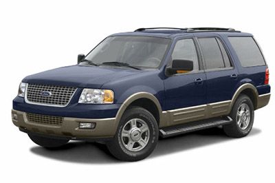
Cigar lighter (power outlet) fuses in the Ford Expedition are the fuses №37 (Cargo area power point), №39 (Instrument panel or floor console power point, Rear console power point) and №41 (Cigar lighter) in the Passenger compartment fuse box.
Table of Contents
Fuse box location
Passenger compartment fuse panel.

To remove the trim panel for access to the fusebox, pull the panel toward you and swing it out away from the side and remove it. To reinstall it, line up the tabs with the grooves on the panel, then push it shut.
To remove the fuse box cover, place a finger behind the PULL tab and your thumb above the PULL tab as shown in the illustration, then pull the cover off. To reinstall the fusebox cover, place the top part of the cover on the fuse panel, then push the bottom part of the cover until you hear it click shut. Gently pull on the cover to make sure it is seated properly.
Fuse box diagrams

Learn more:

- Forum Listing
- Marketplace
- Advanced Search
- Ford 03-07 6.0L Powerstroke Forums
- General 6.0L Discussion
6.0L Electrical Schematics (2004, YMMV)

- Add to quote
I have posted these docs to 3 or 4 different threads. Whenever a new thread pops up, I end up hunting around for them. I am creating this thread so that it will be easier for me to find. ...or maybe some nice mod (Hey! They exist!!) will stickify it and make it easy for everyone to find. These docs are for a 2004 6.0, so accessories for later trucks (like the gluteal warmer/massager that was so popular in the 2005-6 model years and that goofy 2007 dash espresso machine) will not be adequately described. Please keep model year differences in mind. There are 8 documents straight from the Service Manual and a more simple standalone document. I will post the first five here and the remaining four in the next post. Enjoy.
Attachments
- Super Duty_04-Electrical and connectors - 1 of 8.pdf 2 MB Views: 2,465
- Super Duty_04-Electrical and connectors - 2 of 8.pdf 1.7 MB Views: 1,997
- Super Duty_04-Electrical and connectors - 3 of 8.pdf 3.8 MB Views: 1,991
- Super Duty_04-Electrical and connectors - 4 of 8.pdf 3 MB Views: 1,650
- Super Duty_04-Electrical and connectors - 5 of 8.pdf 4.4 MB Views: 1,784
...and the rest.
- Super Duty_04-Electrical and connectors - 6 of 8.pdf 4.6 MB Views: 1,777
- Super Duty_04-Electrical and connectors - 7 of 8.pdf 2.9 MB Views: 1,431
- Super Duty_04-Electrical and connectors - 8 of 8.pdf 3 MB Views: 1,405
- 6_0L Engine Electronic Wiring Diagram.PDF 990.6 KB Views: 1,308

Thank you from many of us !

Since finding a nice mod to make this a "sticky" may be a bit difficult today (or anytime), you could link this thread in your Wiring Diagram thread that's already stuck. https://www.powerstroke.org/forum/general-6-0l-discussion/1118001-hi-res-single-page-6-0l-wiring-diagram-pdfs.html
G8orFord said: Since finding a nice mod to make this a "sticky" may be a bit difficult today (or anytime), you could link this thread in your Wiring Diagram thread that's already stuck. Click to expand...
Much obliged, sir.
why this wasn't already a Sticky :dunno: but it's stuck now for ya
Awesome post, do you have the schematics for 2003 Ford F250, great resource
That`s really great! Thanks!

Thank you so much for this. Are these for F250 as well as F350? The document headings indicate for only both.

Awesome and a Big ol THANK YOU SIR
- ?
- 267.8K members
Top Contributors this Month

Auto Genius
Ford expedition (2003 – 2006) – fuse box diagram.
Year of production: 2003, 2004, 2005, 2006
Power distribution box/passenger compartment
The fuse panel is located under the right-hand side of the instrument panel.
WARNING: Terminal and harness assignments for individual connectors will vary depending on vehicle equipment level, model, and market.
2004 Ford Expedition fuse box diagram
Ford Expedition fuse box diagrams change across years, pick the right year of your vehicle: 2021 2020 2019 2018 2017 2016 2015 2014 2013 2012 2011 2010 2009 2008 2007 2006 2005 2004 2003 2002 2001 2000 1999 1998 1997

Did you find the website helpful?

IMAGES
VIDEO
COMMENTS
To check a fuse, look at the silver-colored band inside the fuse. If the band is broken or melted, replace the fuse. Notice. Before replacing fuses check that the key has been removed from the ignition and that all the services are switched off and/or disengaged. Always disconnect the battery before servicing high current fuses.
1999-2000: Not Used. 2001: Ignition Run Power Feed (Customer Access) 28. 15. 1999-2000: Not Used. 2001: DRL, Brake Shift Interlock (BSD, ECM, Overhead Trip Computer (OTC), AUX A/C Components, Hazard Flasher, Speed Control, Vacuum Pump, Backup Lamps, Electronic Shift On The Fly Hublock Solenoid, Heated Seat.
Fuse Layout Ford Excursion 2000-2005. 2000-2001 - is the fuse №3 (Cigar Lighter) in the Instrument panel fuse box, and fuses №7 (Floor Console Auxiliary PowerPoint), №9 (Left Rear Quarter Auxiliary PowerPoint) and №11 (Cargo Auxiliary PowerPoint) in the Engine compartment fuse box. 2002-2005 - fuses №2 (Power point - floor ...
2004 Ford Excursion fuse box diagram. Ford Excursion fuse box diagrams change across years, pick the right year of your vehicle: Type No. Description; Fuse MINI . 15A: 1: Adjustable pedals. Fuse MINI . 20A: 2: Power point - floor console. Fuse MINI . 20A: 3: Power point - 3rd row.
Excursion, Super Duty Series F−250, F−350, F−450, F−550 '04 11−3 Fuse and Relay Information Circuits protected Electric trailer brakes Ignition switch (11572), Run/Start power circuit, Fuel Injector Control Module (FICM) − 6.0L Rear window defrost, Heated mirrors Windshield wiper motor (17508) Auxiliary Climate Control Heated seats
Fuse Box Information | Ford Excursion 2004. Ford Excursion 2004 Fuse Box Diagram. Ford Excursion 2004 Fuses, Relays, Location, Fuse Panel, Layout.
Ford Excursion (1999-2005) - Fuse box. Ford; Ford Excursion (1999-2005) - Fuse box. Arnold 1 year ago 0 10 mins. ... Fuse diagram and relay box - Ford Excursion. Passenger compartment fuse box. 1999-2001 Schematic; Scheme 2002-2005; Fuse box in engine compartment. 1999-2001 schematic; Applies to vehicles new in years: 1999, 2000, 2001 ...
See more on our website: https://fuse-box.info/ford/ford-excursion-2000-2005-fuses-and-relayFuse box diagram (location and assignment of electrical fuses and...
Fuse boxes change across years, pick the year of your vehicle: Fuse box diagrams. 2005 Excursion. Fuse box diagrams. 2004 Excursion. Fuse box diagrams. 2003 Excursion. Fuse box diagrams. 2001 Excursion.
More about Ford Excursion fuses, see our website: https://fusecheck.com/ford/ford-excursion-1999-2005-fuse-diagramFuse Box Diagram Ford Excursion (1999, 2000...
Ford Motor Company Ford Excursion Owner's Guide. 2004 Excursion automobile pdf manual download. Also for: 2004 u137 excursion. ... it is possible that a fuse has blown or the vehicle's brakelamps are not operating properly. ... (RWD) vehicles/Four Wheel Drive (4WD) vehicles (front tires at top of diagram) 2004 U137 Excursion (hdw) Owners ...
2004 Ford Excursion Fuse Box Info | Fuses | Location | Diagrams | Layouthttps://fuseboxinfo.com/index.php/cars/28-ford/4944-ford-excursion-2004-fuses
Ford Excursion (1999 - 2005) Fuse Box Diagram. Jonathan Yarden Jan 25, 2021 · 5 min. read. In this article you will find a description of fuses and relays Ford, with photos of block diagrams and their locations. Highlighted the cigarette lighter fuse (as the most popular thing people look for). Get tips on blown fuses, replacing a fuse, and more.
Fuse Box Information | Ford Excursion 2005. Ford Excursion 2005 Fuse Box Diagram. Ford Excursion 2005 Fuses, Relays, Location, Fuse Panel, Layout.
00 Diesel Ex Wiring diagram. or. Wiring Diagram for rear window defrost circuit 2002-2005 EATC. or. HELP - need wiring diagram for trailer wires from fuse to plug. Sometimes it's not so urgent and we just need a little help or "confidence boost". Starting System 99-01 Diesel.
Advertisements. In this article, we consider the second-generation Ford Expedition (U222), produced from 2003 to 2006. Here you will find fuse box diagrams of Ford Expedition 2003, 2004, 2005 and 2006, get information about the location of the fuse panels inside the car, and learn about the assignment of each fuse (fuse layout) and relay.
The 2000 Ford Excursion has 2 different fuse boxes: Passenger Compartment Fuse Panel diagram. Power distribution box diagram. Ford Excursion fuse box diagrams change across years, pick the right year of your vehicle: Passenger Compartment Fuse Panel. R2.
Ford. Excursion. fuse box and relays diagrams. Explore interactive fuse box and relay diagrams for the Ford Excursion. Fuse boxes change across years, pick the year of your vehicle: Is your car missing?
6_0L Engine Electronic Wiring Diagram.PDF. 990.6 KB Views: 1,307. 2004 F550 CC Lariat. BPD oil cooler relocation and upgraded EGR cooler (spooled), BPD oil bypass filtration, aFe Magnum Force CAI, Mishi radiator, 7.3L fan clutch, EC1 ELC, XDP coolant bypass filtration, '08 trans pan/filter, PTP direct clutch solenoid, blue spring, 6.4 starter ...
Glove box lamp, Cargo area lamp, Outside mirror puddle lamps, Instrument cluster (interior lamps) R305. Horn relay: Dual note horn. WARNING: Terminal and harness assignments for individual connectors will vary depending on vehicle equipment level, model, and market. Expedition, Ford electricity. Ford Expedition (2003 - 2006) - fuse box diagram.
1. Run/Accessory - Front wiper motor, Instrument cluster, Rear wiper motor, Tire Pressure Monitor System (TPMS) module. Fuse MINI. 20A. 2. Turn signal/Hazard flasher, Stoplamp switch, IVD (AdvanceTrac) stoplamps relay, Stoplamps, Center high-mount stop light (CHMSL), Turn signal lamps. Fuse MINI.