
Fuse Box Diagrams
All automotive fuse box diagrams in one place

Ford Excursion (2000-2005) fuses and relays
Ad vertisements
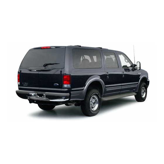
The heavy-duty SUV Ford Excursion was produced from 2000 to 2005. In this article, you will find fuse box diagrams of Ford Excursion 2000, 2001, 2002, 2003, 2004 and 2005 , get information about the location of the fuse panels inside the car, and learn about the assignment of each fuse (fuse layout) and relay.
Fuse Layout Ford Excursion 2000-2005

Cigar lighter (power outlet) fuses: 2000-2001 – is the fuse №3 (Cigar Lighter) in the Instrument panel fuse box, and fuses №7 (Floor Console Auxiliary PowerPoint), №9 (Left Rear Quarter Auxiliary PowerPoint) and №11 (Cargo Auxiliary PowerPoint) in the Engine compartment fuse box. 2002-2005 – fuses №2 (Power point – floor console), №3 (Power point – 3rd row), №4 (Power point – instrument panel), №5 (Power point – right rear quarter) and №12 (Cigar lighter) in the Passenger compartment fuse box.
Table of Contents
Fuse box location
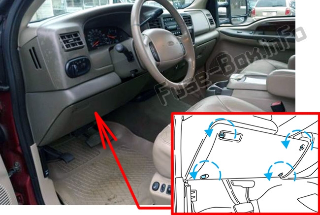
Passenger compartment.
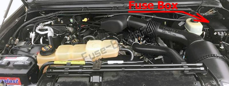
Engine compartment fuse box (if equipped)
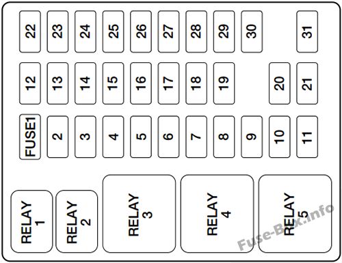
Fuse box diagrams
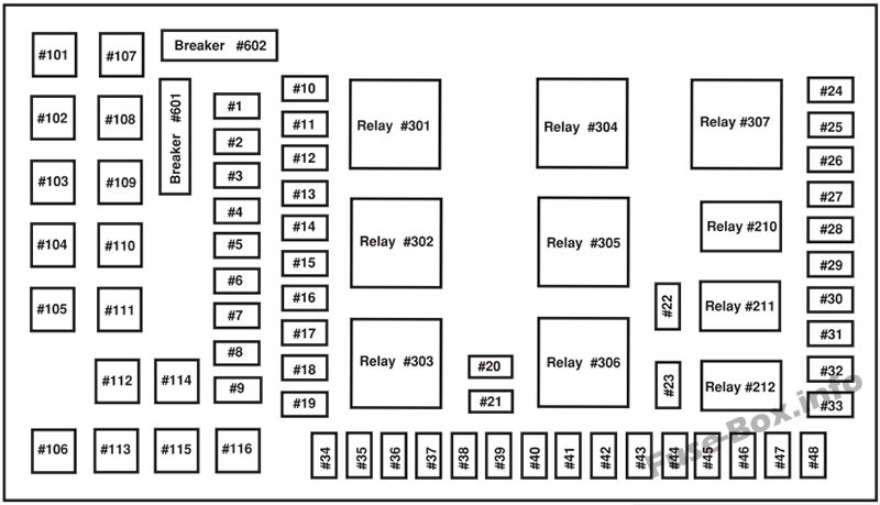
Engine compartment

Passenger compartment / Power distribution box
Learn more:


- You are here:
Ford Excursion 2001 Fuse Box
Fuse box informations | cars.
Ford Excursion 2001 Fuse Box Info
Passenger compartment fuse box location:
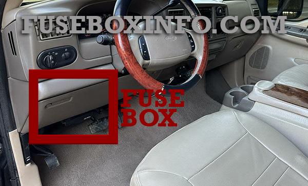
The fuse box is located below and to the left of the steering wheel by the brake pedal.
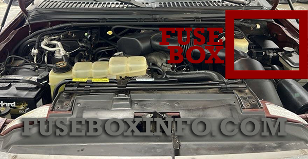
Engine compartment fuse box location:
Fuse Box Diagram | Layout
Passenger compartment fuse box:
Engine compartment fuse box:
- Ford Excursion
Related Vehicles
Ford transit 2024 fuse box, ford puma 2024 fuse box, ford mustang mach-e 2024 fuse box.
- Opel Zafira Life 2023 Fuse Box 19 April 2024
- Opel Zafira Life 2022 Fuse Box 19 April 2024
- Opel Zafira Life 2021 Fuse Box 19 April 2024
Fuse Box Info
- Dodge Ram 1500 2020 Fuse Box
- Jeep Compass 2018 Fuse Box
- Jeep Grand Cherokee 2021 Fuse Box
- Dodge Ram 2500 2020 Fuse Box
- Jeep Grand Cherokee 2020 Fuse Box
- Dodge Ram 1500 2019 Fuse Box

- Motorcycles
- Shopping Cart 0
2001 Ford Excursion Fuses & Components

Popular Products
- 2001 Ford Excursion Limited
- 2001 Ford Excursion XLT
- 01 Ford Excursion Quality Accessories
- Ford Manuals
- 2001 Excursion
- Owner's manual
Ford 2001 Excursion Owner's Manual
- page of 249 Go / 249
Table of Contents
- Breaking-In Your Vehicle
- Emission Warranty
- Vehicle Symbol Glossary
- Warning Lights and Chimes
- Service Engine Soon
- Air Bag Readiness
- Light Turns on Solid
- Light Is Blinking
- Transmission Control Indicator Light (TCIL)
- Safety Belt
- Brake System Warning
- Anti-Lock Brake System (ABS)
- Turn Signal
- Charging System
- Four Wheel Drive Indicator
- Safety Belt Warning Chime
- Securilock Anti-Theft System
- Oil Pressure/Engine Coolant
- Supplemental Restraint System (SRS) Warning Chime
- Key-In-Ignition Warning Chime
- Headlamps on Warning Chime
- Speedometer
- Engine Coolant Temperature Gauge
- Trip Odometer
- Engine Oil Pressure Gauge
- Battery Voltage Gauge
- Headlamp Control
- Autolamp Control
- Panel Dimmer Control
- Power Adjustable Foot Pedals
- 4WD Control
- Reverse Sensing System
- Auxiliary Power Point
- Climate Control System
- Manual Heating and Air Conditioning System
- Fan Speed Control
- Temperature Control Knob
- Mode Selector Control
- Operating Tips
- Auxiliary A/C-Heater Controls
- Rear Window Defroster
- Using Your Audio System
- Premium AM/FM Stereo/Cassette/Single CD
- Volume/Power Control
- AM/FM Select in Radio Mode
- AM/FM Select in Tape Mode
- Tune Adjust in Radio Mode
- Tune Adjust for CD Changer
- Scan Function in Radio Mode
- Seek Function in Tape Mode
- Seek Function in Radio Mode
- Seek Function for CD or CD Changer
- Scan Function in Tape Mode
- Scan Function in CD or CD Changer Mode
- Radio Station Memory Preset
- Setting Memory Preset Stations
- Starting Autoset Memory Preset
- Bass Adjust
- Treble Adjust
- Speaker Balance Adjust
- Speaker Fade Adjust
- Tape/CD Select
- Eject Function
- Tape Direction Select
- Fast Forward
- Dolby Noise Reduction
- Compression Adjust
- Shuffle Feature
- Setting the Clock
- Audiophile AM/FM Stereo in Dash Six CD Radio
- Premium AM/FM Stereo in Dash Six CD Radio
- Starting Autostore
- Display Description
- Traffic Announcements
- RDS Traffic Seek Feature
- RDS Traffic Scan Feature
- Radio Data System (RDS) Feature
- Digital Signal Processing
- Rear Seat Controls
- Using Headphones/Personal Audio System
- Media Select
- Memory Preset Control
- Seek Function
- Cleaning Compact Discs
- Cleaning Cassette Player
- Cassette and Cassette Player Care
- Radio Frequency Information
- Radio Reception Factors
- Positions of the Ignition
- To Turn Speed Control off
- To Turn Speed Control on
- Turn Signal Control
- To Set a Speed
- To Set a Higher Set Speed
- To Set a Lower Set Speed
- To Disengage Speed Control
- To Return to a Previously Set Speed
- Indicator Light
- Tilt Steering Wheel
- Hazard Flasher
- Windshield Wiper/Washer Controls
- Deactivating Overdrive
- Rear Window Wiper/Washer Controls
- Activating Overdrive
- Speed Dependent Wipers
- Power Windows
- Power Door Locks
- One Touch down
- Window Lock
- Accessory Delay
- Childproof Doro Locks
- Power Side View Mirrors
- Fold-Away Mirrors
- Heated Outside Mirrors
- Installing a Garage Door Opener
- Overhead Console
- Forward Storage bin
- Signal Mirrors
- Power Quarter Rear Windows
- Automatic Dimming Inside Rear View Mirror
- Trip Computer
- Illuminated Visor Mirror
- English/Metric Display
- Mode Control
- Outside Air Temperature
- Compass Zone Adjustment
- Compass Calibration Adjustment
- Interior Lamps
- Dome/Map Lamps
- Rear Courtesy/Reading Lamps
- Rear Dome Lamp
- Center Console
- Remote Entry System
- Unlocking the Doors
- Locking the Doors
- Sounding a Panic Alarm
- Replacing the Battery
- Illuminated Entry
- Replacing Lost Transmitters
- Programming Remote Transmitters
- Keyless Entry System
- Programming Your Own Personal Entry Code
- Unlocking the Doors with the Keyless Entry System
- Securilock Passive Anti-Theft System
- Locking the Doors with the Keyless Entry System
- Automatic Arming
- Automatic Disarming
- Key Information
- Programming Spare Keys
- Full Bench Seat
- 60/40 Split Bench Seat
- Captain’s Chair
- Adjusting the Front Power Seat
- Using the Manual Lumbar Support
- Heated Seats
- Head Restraints
- Rear Folding Bench Seat
- Folding down Rear Seats into Load Floor
- Returning the Seat to Upright
- Reclining the Seatback
- Third Row Seat
- Accessing the Third Row Seat
- Folding down the Third Row Seat
- Removing the Third Row Seat
- Installing the Third Row Seat
- Safety Restraints Precautions
- Combination Lap and Shoulder Belts
- Vehicle Sensitive Mode
- Automatic Locking Mode
- How to Disengage the Automatic Locking Mode
- Energy Management Feature
- Safety Belt Replacement Label
- Safety Belt Pretensioner
- Front and Second Row Safety Belt Height Adjustment
- Adjusting the Lap Belt
- Safety Belt Extension Assembly
- Safety Belt Warning Light and Indicator Chime
- Conditions of Operation
- Belt Minder
- One Time Disable
- Deactivating/Activating the Belt Minder Feature
- Air Bag Supplemental Restraint System (SRS)
- Safety Belt Maintenance
- Important Supplemental Restraint System (SRS) Precautions
- Children and Air Bags
- How Does the Air Bag Supplemental Restraint System Work?
- Determining if the System Is Operational
- Safety Restraints for Children
- Disposal of Air Bags and Air Bag Equipped Vehicles (Including Pretensioners)
- Important Child Restraint Precautions
- Children and Safety Belts
- Safety Seats for Children
- Child and Infant or Child Safety Seats
- Installing Child Safety Seats in Combination Lap and Shoulder Belt Seating Positions
- Attaching Child Safety Seats with Tether Straps
- Preparing to Start Your Vehicle
- Starting the Engine
- Using the Engine Block Heater
- Guarding against Exhaust Fumes
- Important Ventilating Information
- Four-Wheel Anti-Lock Brake System (ABS)
- Using Four Wheel ABS
- ABS Warning Lamp
- Parking Brake
- Steering Your Vehicle
- Brake-Shift Interlock
- Automatic Transmission Operation
- Preparing to Drive Your Vehicle
- Driving with a 4–Speed Automatic Transmission
- Understanding Gearshift Positions
- R (Reverse)
- N (Neutral)
- Forced Downshifts
- Four-Wheel Drive (4WD) Operation
- Shift Strategy (4R100 Automatic Transmission)
- Electronic Shift on the Fly (ESOF) 4X4 System
- Positions of the Electronic Shift System
- Using the Electronic Shift 4WD System
- 4WD System Indicator Lights
- Shifting from 4X4 HIGH (4WD High) to 4X4 LOW (4WD Low)
- Shifting from 2WD (2WD High) to 4X4 HIGH (4WD High)
- Shifting from 4X4 HIGH (4WD High) to 2WD (2WD High)
- Driving Off-Road with 4WD
- Shifting from 4X4 LOW (4WD Low) to 4X4 HIGH (4WD High) or 2WD (2WD High)
- If Your Vehicle Gets Stuck
- Mud and Water
- Driving on Hilly or Sloping Terrain
- Driving on Snow and Ice
- Vehicle Loading
- Special Loading Instructions for Owners of Pickup Trucks and Utility-Type Vehicles
- Driving through Water
- Calculating the Load Your Vehicle Can Carry/Tow
- Trailer Towing
- Preparing to Tow
- Load Equalizing Hitch
- Safety Chains
- Trailer Brakes
- Trailer Lamps
- Using a Step Bumper
- Driving While You Tow
- Launching or Retrieving a Boat
- Servicing after Towing
- Trailer Towing Tips
- Luggage Rack
- Recreational Towing (All Wheels on the Ground)
- Getting Roadside Assistance
- Using Roadside Assistance
- Resetting the Fuel Pump Shut-Off Switch
- Roadside Coverage Beyond Basic Warranty
- Passenger Compartment Fuse Panel
- Standard Fuse Amperage Rating and Color
- Power Distribution Box
- Changing the Tires
- Spare Tire Information
- Location of the Spare Tire and Tools
- Tire Change Procedure
- Jump Starting Your Vehicle
- Preparing Your Vehicle
- Connecting the Jumper Cables
- Removing the Jumper Cables
- Wrecker Towing
- Precautions When Servicing Your Vehicle
- Working with the Engine Off/On
- Service Recommendations
- Opening Hood
- Identifying Components in the Engine Compartment
- 5.4L V8/6.8L V10 Gasoline Engines
- Checking the Engine Oil
- Adding Engine Oil
- Engine Oil and Filter Recommendations
- Checking and Adding Brake Fluid—Gasoline Engine
- Checking and Adding Brake Fluid—Diesel Engine
- Checking Engine Coolant
- Checking and Adding Washer Fluid for the Liftgate
- Windshield Washer Fluid
- Adding Engine Coolant
- Recycled Engine Coolant
- Coolant Refill Capacity
- Severe Climates
- What You Should Know about Fail-Safe Cooling
- How Fail-Safe Cooling Works
- When Fail-Safe Mode Is Activated
- Checking and Adding Power Steering Fluid
- Checking Automatic Transmission Fluid
- Low Transmission Fluid Level
- Adjusting Automatic Transmission Fluid Levels
- High Fluid Level
- Correct Fluid Level
- Checking and Adding Transfer Case Fluid
- Air Filter Maintenance
- Changing the Air Filter Element (Gasoline Engines Only)
- Traction-Lok Axle
- Windshield Wiper Blades
- Checking the Wiper Blades
- Rear Window Wiper Blades
- Information about Uniform Tire Quality Grading
- Changing the Wiper Blades
- Tire Rotation
- Servicing Your Tires
- Checking the Tire Pressure
- Replacing the Tires
- Snow Tires and Chains
- What You Should Know about Automotive Fuels
- Choosing the Right Fuel
- Octane Recommendations
- Fuel Quality
- Cleaner Air
- Running out of Fuel
- Fuel Filler Cap
- Measuring Techniques
- Fuel Filter
- Essentials of Good Fuel Economy
- Filling the Tank
- Calculating Fuel Economy
- Driving Style — Good Driving and Fuel Economy Habits
- Maintenance
- EPA Window Sticker
- Emission Control System
- Readiness for Inspection/Maintenance (I/M) Testing
- Replacing Exterior Bulbs
- Replacing Headlamp Bulbs
- Replacing Front Parking/Turn Signal Bulbs
- Replacing Foglamp Bulbs
- Replacing Tail Lamp/Turn/Backup Lamp Bulbs
- Replacing High-Mount Brakelamp Bulbs
- Using the Right Bulbs
- Replacing License Plate Lamp Bulbs
- Interior Bulbs
- Aiming the Headlamps
- Cleaning and Caring for Your Vehicle
- Washing Your Vehicle
- Waxing Your Vehicle
- Cleaning the Engine
- Cleaning the Wheels
- Repairing Paint Chips
- Cleaning Non-Painted Plastic Exterior Parts
- Cleaning the Exterior Lamps
- Cleaning the Windshield, Wiper Blades and Rear Window
- Cleaning the Instrument Panel
- Cleaning the Instrument Cluster Lens
- Cleaning the Interior Fabric
- Cleaning and Maintaining the Safety Belts
- Cleaning Leather Seats
- Motorcraft Part Numbers
- Refill Capacities
Advertisement
Quick Links
- 1 Controls and Features
- 3 Maintenance and Care
- 4 Capacities and Specifications
- Download this manual
Related Manuals for Ford 2001 Excursion

Summary of Contents for Ford 2001 Excursion
- Page 1 All rights reserved. Reproduction by any means, electronic or mechanical including photocopying, recording or by any information storage and retrieval system or translation in whole or part is not permitted without written authorization from Ford Motor Company. Ford may change the contents without notice and without incurring obligation.
Page 2: Introduction
- Page 3 INFORMATION ABOUT THIS GUIDE The information found in this guide was in effect at the time of printing. Ford may change the contents without notice and without incurring obligation. EMISSION WARRANTY The New Vehicle Limited Warranty includes Bumper to Bumper Coverage, Safety Restraint Coverage, Corrosion Coverage, and 7.3L Power Stroke...
- Page 4 Introduction These are some of the symbols you may see on your vehicle. Vehicle Symbol Glossary Safety Alert Fasten Safety Belt Air Bag-Side Child Seat Installation Warning Brake System Brake Fluid - Non-Petroleum Based Master Lighting Switch Fog Lamps-Front Fuel Pump Reset Windshield Defrost/Demist Power Windows...
- Page 5 Vehicle Symbol Glossary Child Safety Door Lock/Unlock Panic Alarm Engine Coolant Do Not Open When Hot Avoid Smoking, Flames, or Sparks Explosive Gas Power Steering Fluid Emission System Passenger Compartment Air Filter Check fuel cap Introduction Interior Luggage Compartment Release Symbol Engine Oil Engine Coolant...
Page 6: Instrumentation
- Page 7 Instrumentation Audio system Rear window Gearshift lever (pg. 29) defroster control (pg. 128) (pg. 28) HIGH 4WD selector* (pg. 133) Auxiliary Climate control Power adjustable power point system Reverse foot pedals* (pg. 22) (pg. 23) sensing system* (pg. 19) (pg. 20)
- Page 8 Instrumentation WARNING LIGHTS AND CHIMES FUEL FILL FUEL Low fuel Illuminates as an early reminder of a low fuel condition indicated on the fuel gauge (refer to Fuel Gauge in this chapter for more information). When refueling, after the light comes on, the amount of fuel that is added will be less than the advertised capacity since there is fuel still in the tank.
- Page 9 What you should do if the Service Engine Soon light illuminates Light turns on solid: This means that the OBD II system has detected a malfunction. Temporary malfunctions may cause your Service Engine Soon light to illuminate. Examples are: 1. The vehicle has run out of fuel. (The engine may misfire or run poorly.) 2.
- Page 10 Instrumentation Transmission control indicator light (TCIL) (if equipped) Illuminates when the Transmission Control Switch (TCS), refer to OVERDRIVE Overdrive control in the Controls and Features chapter, has been pushed turning the transmission overdrive function OFF. When the TCIL (the word OFF on the gear shift) light is on, the transmission does not operate in the overdrive mode, refer to the Driving chapter for transmission function and operation.
- Page 11 Instrumentation Turn signal Illuminates when the left or right turn signal or the hazard lights are turned on. If one or both of the indicators stay on continuously or flash faster, check for a burned-out turn signal bulb. Refer to Bulbs in the Maintenance and care chapter. High beams Illuminates when the high beam headlamps are turned on.
- Page 12 Instrumentation Door ajar Illuminates when the ignition is in the ON position and any door is DOOR open. It may also momentarily AJAR illuminate after the engine is started and all doors are closed. Oil pressure/Engine coolant This light will come on when the key is in the ON position and the: •...
- Page 13 Supplemental restraint system (SRS) warning chime For information on the SRS warning chime, refer to the Seating and safety restraints chapter. Key-in-ignition warning chime Sounds when the ignition key is left in the ignition in the OFF/LOCK or ACC position and the driver’s door is opened. Headlamps on warning chime Sounds when the headlamps or parking lamps are on, the ignition is off (and the key is not in the ignition) and the driver’s door is opened.
- Page 14 Instrumentation Speedometer Indicates the current vehicle speed. Engine coolant temperature gauge Indicates the temperature of the engine coolant. At normal operating temperature, the needle remains within the normal area (the area between the “H” and “C”). If it enters the red section, the engine is overheating.
- Page 15 Instrumentation Odometer Registers the total kilometers (miles) of the vehicle. Trip odometer Registers the kilometers (miles) of individual journeys. To reset, depress the control. Tachometer Indicates the engine speed in revolutions per minute. Driving with your tachometer pointer continuously at the top of the scale may damage the engine.
- Page 16 Instrumentation Battery voltage gauge This shows the battery voltage when the ignition is in the ON position. If the pointer moves and stays outside the normal operating range (as indicated by arrows), have the vehicle’s electrical system checked as soon as possible. Engine oil pressure gauge This shows the engine oil pressure in the system.
Page 17: Controls And Features
- Page 18 Controls and features High beams Push forward to activate. Pull toward you to deactivate. Flash to pass Pull toward you to activate and release to deactivate. Daytime running lamps (DRL) (if equipped) Turns the headlamps on with a reduced output. To activate: •...
- Page 19 PANEL DIMMER CONTROL Use to adjust the brightness of the instrument panel during headlamp and parklamp operation. • Rotate up to brighten. • Rotate down to dim. • Rotate to full up position (past detent) to turn on interior lamps. •...
- Page 20 Controls and features REVERSE SENSING SYSTEM (IF EQUIPPED) The reverse sensing system (RSS) sounds a tone to warn the driver of obstacles near the rear bumper when the reverse gear is selected. To help avoid personal injury, please read and understand the limitations on the reverse sensing system described below.
- Page 21 Controls and features The reverse sensing system detects obstacles within approximately 1.8 meters (5.9 ft.) of the rear bumper with a decreased coverage area at the outer corners of the bumper, (refer to the figures for approximate zone coverage areas). As you move closer to the obstacle, the rate of the tone increases.
- Page 22 Controls and features AUXILIARY POWER POINT Power outlets are designed for accessory plugs only. Do not hang any type of accessory or accessory bracket from the plug. Improper use of the power outlet can cause damage not covered by your warranty. The power point is an additional power source for electrical accessories.
- Page 23 • Located in the left side storage compartment in the third row seating position. • Located on the right trim panel in the rear cargo area. CLIMATE CONTROL SYSTEM Manual heating and air conditioning system Fan speed control Controls the volume of air circulated in the vehicle.
- Page 24 Controls and features Mode selector control Controls the direction of the airflow to the inside of the vehicle. The air conditioning compressor can operate in all modes except . However, the air conditioning will only function if the outside temperature is about 6°C (43°F) or higher. Since the air conditioner removes considerable moisture from the air during operation, it is normal if clear water drips on the ground under the air conditioner drain while the system is working and even after you...
- Page 25 • (Floor and defrost) -Distributes outside air through the windshield defroster ducts and the floor ducts. Heating and air conditioning capabilities are provided in this mode. For added customer comfort, the air distributed through the floor ducts will be slightly warmer than the air sent to the windshield defroster ducts. If the temperature is about 6°C (43°F) or higher, the air conditioner will automatically dehumidify the air to reduce fogging.
- Page 26 Controls and features • Remove any snow, ice or leaves from the air intake area at the base of the windshield. • If your vehicle has been parked with the windows closed during hot weather, the air conditioner will do a much faster job of cooling if you drive for two or three minutes with the windows open.
- Page 27 Controls and features Your auxiliary A/C controls are located in the overhead console. In order for the auxiliary A/C-heater controls to function, the driver’s REAR auxiliary A/C-heater control must be set to REAR. COOL WARM PANEL FLOOR The instrument panel A/C - heater controls must be on in order for the auxiliary A/C-heater to operate.
- Page 28 Controls and features Turn the temperature control to the desired temperature. If the front seat control panel is set to MAX A/C, only cool air will be provided because no heating is available in this mode. You can get warm or cool air through either the overhead registers or floor vent by turning the auxiliary mode selector: •...
- Page 29 USING YOUR AUDIO SYSTEM Premium AM/FM Stereo/Cassette/Single CD VOL PUSH ON FM 1 DOLBY B NR SEEK TUNE SCAN BASS TREB SIDE 1-2 Volume/power control Press the control to turn the audio system on or off. Audio power can also be turned on by pressing the AM/FM select control or the tape/CD select control.
- Page 30 Controls and features If the volume is set above a certain level and the ignition is turned off, the volume will come back on at a “nominal” listening level when the ignition switch is turned back on. AM/FM select The AM/FM select control works in radio, tape and CD modes.
- Page 31 • Press to select the next disc in the CD changer. Hold the control to fast-forward through the remaining discs. Seek function The seek function control works in radio, tape or CD mode. Seek function in radio mode • Press to find the next listenable station down the frequency band.
- Page 32 Controls and features Scan function in tape mode Press the SCAN control to hear a short sampling of all selections on the tape. (The tape scans in a forward direction. At the end of the tape’s first side, direction automatically reverses to the opposite side of the tape.) To stop on a particular selection, press the control again.
- Page 33 Starting autoset memory preset 1. Select a frequency using the AM/FM select controls. 2. Press the AUTO control. 3. When the first six strong stations are filled, the station stored in memory preset control 1 will start playing. If there are less than six strong stations available on the frequency band, the remaining memory preset controls will all store the last strong station available.
- Page 34 Controls and features Press the TREB control then press: • to decrease the treble output • to increase the treble output. Speaker balance adjust Speaker sound distribution can be adjusted between the right and left speakers. Press the BAL control then press: •...
- Page 35 • To begin CD play (if CD(s) are loaded), press the CD control. The first track of the disc will begin playing. If returning from radio or tape mode, CD play will begin where it stopped last. With the dual media audio system, press the CD control to toggle between single CD and CD changer play (if equipped).
- Page 36 Controls and features Press the EJ control to stop and eject a CD. Dolby noise reduction Dolby noise reduction operates in tape mode. Dolby noise reduction reduces the amount of hiss and static during tape playback. Press the control to activate (and deactivate) the Dolby noise reduction.
- Page 37 Setting the clock To set the hour, press and hold the CLK control and press SEEK: • to decrease hours and • to increase hours. To set the minute, press and hold the CLK control and press TUNE: • to decrease minutes and •...
- Page 38 Controls and features The CLK button will allow you to switch between media display mode (radio station, stereo information, etc.) and clock display mode (time). When in clock mode, the media information will display for 10 seconds, when the radio is turned on, and then revert to clock information.
- Page 39 Premium AM/FM Stereo In Dash Six CD Radio DISC SHUF SCAN TUNE LOAD PUSH ON Volume/power control Press the control to turn the audio system on or off. Turn the control to raise or lower volume. If the volume is set above a certain level and the ignition is turned off, the volume will come back on at a “nominal”...
- Page 40 Controls and features AM/FM select The AM/FM select control works in radio and CD modes. AM/FM select in radio mode This control allows you to select AM or FM frequency bands. Press the control to switch between AM, FM1 or FM2 memory preset stations. AM/FM select in CD mode Press this control to stop CD play and begin radio play.
- Page 41 Seek function The seek function works in radio or CD mode. Seek function in radio mode • Press to find the next listenable station down the frequency band. SEEK DOWN will display. • Press to find the next listenable station up the frequency band. SEEK UP will display.
- Page 42 Controls and features Radio station memory preset The radio is equipped with six station memory preset controls. These controls can be used to select up to six preset AM stations and twelve FM stations (six in FM1 and six in FM2). Setting memory preset stations 1.
- Page 43 Controls and features To deactivate autoset and return to your audio system’s manually set memory stations, press the AM/FM control again. CD select CD mode may be entered by pressing the CD control and the LOAD control. Load the CD into the audio system.
- Page 44 Controls and features Press the LOAD control. (You can choose which slot will be loaded by pressing the desired preset number. If you do not choose a slot, the system will choose the next available one.) Wait until the CD door opens. Load the CD into the player.
- Page 45 Controls and features Rewind The rewind control works in CD modes. Press and hold the REW control until the desired selection is reached. If the beginning of the disc is reached, the CD will begin play at the first track. Release the control to disengage rewind mode. When in rewind mode, your audio system will automatically lower the volume level of the playing media.
- Page 46 Controls and features On Audiophile audios, press the MENU control until compression status is displayed. Press the SEL control to enable the compression feature when COMP OFF is displayed. Press the SEL control again to disable the feature when COMP ON is displayed. On Premium audios, press the COMP control until COMP ON is displayed.
- Page 47 Controls and features Menu mode The MENU control allows you to access many different features within your audio system. There are three sets of menus available depending upon which mode or feature is activated. While in FM mode, two menus are available. If RDS is turned off, you can access the following: •...
- Page 48 Controls and features Traffic announcements This feature allows you to hear traffic announcements. When in this mode, traffic announcements will interrupt radio and CD play. When in FM mode and RDS is activated, press the MENU until TRAFFIC OFF displays. Press the SEL control to engage the feature.
- Page 49 Controls and features • Press the SEL control to engage this feature (RDS ON). RDS features: Once the RDS feature is on, press the MENU control to scroll through the following selections: Traffic announcements This feature allows you to hear traffic announcements while in CD mode. These announcements are broadcast by traffic capable RDS stations.
- Page 50 Controls and features • R & B • Religious • Rock • Soft • Top 40 Show This feature allows you to select the type of RDS broadcast information the radio will regularly show in the display. With RDS activated, press the MENU control until SHOW is displayed.
- Page 51 • JAZZ CLUB—jazz club with clearly reflected sounds • HALL—rectangular concert hall capacity of about 2 000 • CHURCH—church with a high vault • STADIUM—outdoor stadium with a capacity of about 30 000 Press the DSP control again to access the occupancy modes. Use the SEL control to optimize the sound based upon the occupants in the vehicle.
- Page 52 Controls and features SIDE 1-2 COMP SHUFFLE To turn on the rear seat controls, press the memory preset controls 3 and 5 at the same time. The will appear in the radio display. Pressing 3 and 5 at the same time again will turn the rear seat controls off.
- Page 53 Media select Push the MEDIA control to toggle between AM, FM1, FM2, tape, CD, or CD changer (if equipped). Memory preset control Push the MEM control successively to allow rear seat passengers to scroll through the six memory presets in AM, FM1, or FM2. Push the MEM control in CD changer mode (if equipped) to advance to the next disc.
- Page 54 Controls and features • Do not insert more than one disc into each slot of the CD changer magazine. Do not insert any promotional (odd shaped or sized) discs, or discs with removable labels into the CD player as jamming may occur.
- Page 55 • Terrain. Hills, mountains and tall buildings between your vehicle’s antenna and the radio station signal can cause FM reception problems. Static can be caused on AM stations by power lines, electric fences, traffic lights and thunderstorms. Moving away from an interfering structure (out of its “shadow”) returns your reception to normal.
- Page 56 Controls and features TURN SIGNAL CONTROL • Push down to activate the left turn signal. • Push up to activate the right turn signal. SPEED CONTROL To turn speed control on • Press ON. Vehicle speed cannot be controlled until the vehicle is traveling at or above 48 km/h (30 mph).
- Page 57 To set a speed • Press SET ACCEL. For speed control to operate, the speed control must be ON and the vehicle speed must be greater than 48 km/h (30 mph). If you drive up or down a steep hill, your vehicle speed may vary momentarily slower or faster than the set speed.
- Page 58 Controls and features You can accelerate with the accelerator pedal at any time during speed control usage. Releasing the accelerator pedal will return your vehicle to the previously programmed set speed. To set a lower set speed • Press and hold COAST. Release the control when the desired speed is reached or •...
- Page 59 Pressing OFF will erase the previously programmed set speed. To return to a previously set speed • Press RES. For RES to operate, the vehicle speed must be faster than 48 km/h (30 mph). Indicator light This light comes on when either the SET ACCEL or RES controls are pressed.
- Page 60 Controls and features TILT STEERING WHEEL Pull the tilt steering control toward you to move the steering wheel up or down. Hold the control while adjusting the wheel to the desired position, then release the control to lock the steering wheel in position. Never adjust the steering wheel when the vehicle is moving.
- Page 61 Controls and features Push (tap) the end of the stalk briefly for a single swipe (no wash). Push and hold for three swipes with wash. Push and hold for a longer wash (up to ten seconds). Rear window wiper/washer controls For rear wiper operation, rotate the rear window wiper and washer control to the desired position.
- Page 62 Controls and features The transmission will operate in all gears except overdrive. To return to normal overdrive mode, press the Transmission Control Switch again. The TCIL (the word OFF) will no longer be illuminated. When you shut off and re-start your vehicle, the transmission will automatically return to normal For additional information about the gearshift lever and the transmission control switch operation refer to the Automatic Transmission...
- Page 63 One touch down • Press AUTO completely down and release quickly. The driver’s window will open fully. Depress again to stop window operation. One touch down can be deactivated during operation by pushing down on the top part of the driver power window control.
- Page 64 Controls and features CHILDPROOF DOOR LOCKS When these locks are set, the rear doors cannot be opened from the inside. The rear doors can be opened from the outside when the doors are unlocked. The childproof locks are located on rear edge of each rear door and must be set separately for each door.
- Page 65 2. Move the control in the direction you wish to tilt the mirror. 3. Return to the center position to lock mirrors in place. 4. Adjust spotter mirrors (if equipped) manually. Fold-away mirrors Fold the side mirrors in carefully when driving through a narrow space, like an automatic car wash.
- Page 66 Controls and features Signal mirrors (if equipped) When the turn signal is activated, the appropriate mirror will show a blinking red arrow. The arrow provides an additional warning to other drivers that your vehicle is about to turn. Driver and passengers seated inside the vehicle cannot see the arrow.
- Page 67 • Place transmitter into storage compartment, control down. • Place the provided height adaptors onto the back of the storage bin door as needed. • Press the storage compartment door to activate the transmitter. Power quarter rear windows (if equipped) Press the portion of the VENT control to open the power rear...
- Page 68 Controls and features Illuminated visor mirror Lift the mirror cover to turn on the visor mirror lamps. TRIP COMPUTER (IF EQUIPPED) The trip computer tells you about the condition of your vehicle through a constant monitor of vehicle systems. You may select display features on the trip computer for a display of status.
- Page 69 Mode control Each press of the MODE control will display a different feature as follows: Average fuel economy. The display will indicate the vehicle’s average fuel economy in liters/100 km (or miles/gallon) since the average fuel economy was last reset. If you calculate your average fuel economy by dividing liters of fuel used by 100 kilometers traveled...
- Page 70 Controls and features • if the vehicle is started while parked on an incline. • if less than 30 liters (8 gallons) of fuel is added to the fuel tank. The fuel range function will flash for five seconds at the following distances based on fuel remaining and fuel economy calculations: •...
- Page 71 Compass zone adjustment 1. Determine which magnetic zone you are in for your geographic location by referring to the zone map. 2. Locate the trip computer on the overhead console. 3. Turn ignition to the ON position. 4. Press and hold both trip computer controls.
- Page 72 Controls and features 1. Locate the trip computer located in the overhead console. 2. Start the vehicle. 3. Press and hold both trip computer controls. After approximately eight seconds, the trip computer will enter CAL mode. MODE CAL mode is indicated when the display lights the “CAL”...
- Page 73 Rear courtesy/reading lamps • Second row courtesy/reading lamp • Third row courtesy/reading lamp The courtesy lamps light when: • any door is opened. • the instrument panel dimmer switch is held up until the courtesy lamps come on. • any of the remote entry controls are pressed and the ignition is OFF. The reading lamps can be turned on by pressing the rocker control.
- Page 74 Controls and features CENTER CONSOLE Your vehicle may be equipped with a variety of console features. These include: • Utility compartment • Coin holder slots • Pen holder Use only soft cups in the cupholder. Hard objects can injure you in a collision. •...
- Page 75 Controls and features Your vehicle is equipped with a remote entry system which allows you to: • unlock the vehicle doors without a key. • lock all the vehicle doors without a key. • activate the personal alarm. The remote entry features only operate with the ignition in the LOCK position.
- Page 76 Controls and features Sounding a panic alarm Press this control to activate the alarm. To deactivate the alarm, press the control again or turn the ignition to ACC or ON. Replacing the battery The remote transmitter is powered by one coin type three-volt lithium battery CR2032 or equivalent.
- Page 77 Illuminated entry The illuminated entry system will turn on the interior lights when the remote transmitter unlock control is pressed. The illuminated entry system will turn off the interior lights if the ignition switch is turned to the ON position, or if the remote transmitter lock control is pressed, or after 25 seconds of illumination.
- Page 78 Controls and features Programming remote transmitters It is necessary to have all (maximum of four — original and/or new) of your remote transmitters available prior to beginning this procedure. To program the transmitters yourself: • Place the key in the ignition and turn from 2 (LOCK) to 3 (OFF) and cycle between 3 (OFF) and 4(ON) eight times in rapid...
- Page 79 Programming your own personal entry code To program your own code: 1. Enter factory set code (keypad will illuminate for five seconds when a key is pressed). 2. Press 1/2 control within five seconds of step 1. 3. Enter your personal 5 digit code. Enter each digit within five seconds of previous one.
- Page 80 The SecuriLock passive anti-theft system is not compatible with non-Ford aftermarket remote start systems. Use of these systems may result in vehicle starting problems and a loss of security protection. Automatic arming...
- Page 81 OFF and restart the engine with all other objects on the key ring held away from the ignition key. Check to make sure the coded key ignition key is an approved Ford coded key ignition key. If your keys are lost or stolen you will need to do the following: •...
- Page 82 Controls and features The correct coded key key must be used for your vehicle. The use of the wrong type of coded key key may lead to a “NO-START” condition. If an unprogrammed key is used in the ignition it will cause a “NO START”...
- Page 83 If not successful, the new coded key(s) will not start the vehicle’s engine and the theft indicator will flash on and off and you may repeat steps 1 through 6. If failure repeats, bring your vehicle to your dealership to have the new spare key(s) programmed.
- Page 84 Controls and features The cargo doors and liftgate should be closed before driving your vehicle. Leaving the liftgate and/or the cargo doors open could cause serious damage to the TriDoors and its components as well as allowing carbon monoxide to enter the vehicle. If you must drive with the cargo doors and liftgate window open, keep the vents open so outside air comes into the vehicle.
Page 85: Seating And Safety Restraints
- Page 86 Seating and safety restraints Captain’s chair (if equipped) • Lift the track release bar to move the seat forward or rearward. Make sure that the seat is relatched into place. • Pull the seatback handle up to recline the seat. Adjusting the front power seat (if equipped) Never adjust the driver’s seat or seatback when the vehicle is moving.
- Page 87 Seating and safety restraints Press front to raise or lower the front portion of the seat cushion. Press rear to raise or lower the rear portion of the seat cushion. Press the control to move the seat forward, backward, up or down. Using the manual lumbar support Turn the lumbar support control toward the front of vehicle to move...
- Page 88 Seating and safety restraints Heated seats (if equipped) To operate the heated seats: • Push control to activate. • Push again to deactivate. The indicator light on the control will illuminate when activated. REAR SEATS Head restraints Your vehicle’s seats are equipped with head restraints which adjust up and down.
- Page 89 Seating and safety restraints Rear folding bench seat (if equipped) Folding down rear seats into load floor Ensure that no objects such as books, purses or briefcases are on the floor in front of the second row seats before folding them down and insure the seat is fully latched rearward.
- Page 90 Seating and safety restraints 4. Stow headrest into the green caps found on the top of the seat cushion. 5. Lift the lower seat control and flip the seatback down.
- Page 91 Seating and safety restraints 6. Lift up flap on seatback to release closeout panel. 7. Rotate panel to closeout the space between the seatback and the floor. Returning the seat to upright Insure the seat is pulled back to the locked position, whether the seat is occupied or empty.
- Page 92 Seating and safety restraints 4. Remove headrest from storage position and return to 2nd row seatback. Push down headrest completely to secure. Reclining the seatback Lift the control to adjust the seatback. Third row seat (if equipped) The third row seat is equipped with combination lap and shoulder belts in the outboard seating positions and a manual adjust tongue lap belt in the center seating position.
- Page 93 Seating and safety restraints 1. Rotate the upper seat control rearward while pushing the seatback toward the front of the vehicle. 2. Push the seatback toward the front of the vehicle. This releases the seat track and the seat will move forward.
- Page 94 Seating and safety restraints Removing the third row seat From the rear of the vehicle, with the liftgate window and cargo doors open: 1. Pull the seat release lever located on the lower right side of the seatback while pushing the seatback down onto the seat cushion.
- Page 95 Seating and safety restraints • When the rear of the seat is 10–13 cm (4–5 in) above the rear pins, let the seat drop. This will ensure that the seat will properly latch into the floor. 2. Push up on the seat to verify that it is latched into the floor. 3.
- Page 96 Seating and safety restraints Each seating position in your vehicle has a specific safety belt assembly which is made up of one buckle and one tongue that are designed to be used as a pair. 1) Use the shoulder belt on the outside shoulder only.
- Page 97 Seating and safety restraints Vehicle sensitive mode The vehicle sensitive mode is the normal retractor mode, allowing free shoulder belt length adjustment to your movements and locking in response to vehicle movement. For example, if the driver brakes suddenly or turns a corner sharply, or the vehicle receives an impact of approximately 8 km/h (5 mph) or more, the combination safety belts will lock to help reduce forward movement of the driver and passengers.
- Page 98 This indicates the safety belt is now in the automatic locking mode. How to disengage the automatic locking mode Ford recommends that all safety belt assemblies and attaching hardware should be inspected by a qualified technician after any collision. Safety belt assemblies not in use during a collision should also be inspected and replaced if either damage or improper operation is noted.
- Page 99 Seating and safety restraints Energy Management Feature • This vehicle has a seat belt system with an energy management feature at the front outboard seating position to help further reduce the risk of injury in the event of a head-on collision. •...
- Page 100 Seating and safety restraints Safety belt replacement label The short plastic boot on the front safety belt at the passenger outboard anchor location covers a “Replace Belt” label on the safety belt. In the event of a collision, the colored label (REPLACE BELT) may become visible.
- Page 101 Seating and safety restraints Failure to follow these instructions will affect the performance of the safety belts and increase the risk of personal injury. Safety belt pretensioner (if equipped) Your vehicle is equipped with safety belt pretensioners at the driver and front outboard passenger seating positions.
- Page 102 Seating and safety restraints Position the shoulder belt height adjusters so that the belt rests across the middle of your shoulder. Failure to adjust the safety belt properly could reduce the effectiveness of the seat belt and increase the risk of injury in a collision. Lap belts Adjusting the lap belt The lap belt should fit snugly and as low as possible around the...
- Page 103 Seating and safety restraints • 2nd row center seating position (if equipped) The lap belt will adjust automatically. To fasten, grasp the tongue, and with a continuous motion, pull out enough webbing to buckle the tongue into the correct buckle. If you did not pull out enough webbing to reach the buckle, allow the tongue to retract fully before trying to pull it out again.
- Page 104 “I’m not going far” 3 of 4 fatal crashes occur within 25 miles of home. “Belts are Ford designs its safety belts to enhance comfort. If uncomfortable” you are uncomfortable - try different positions for the safety belt upper anchorage and seatback which should be as upright as possible;...
- Page 105 Seating and safety restraints Reasons given... Consider... “Seat belts don’t Safety belts, when used properly, reduce risk of work” death to front seat occupants by 45% in cars, and by 60% in light trucks. “Traffic is light” Nearly 1 of 2 deaths occur in single-vehicle crashes, many when no other vehicles are around.
- Page 106 Seating and safety restraints • the ignition switch is in the OFF position • all vehicle doors are closed • the driver’s safety belt is unbuckled • the parklamps/headlamps are in OFF position (If vehicle is equipped with Autolamps, this will not affect the procedure.) To reduce the risk of injury, do not deactivate/activate the Belt Minder feature while driving the vehicle.
- Page 107 In the event of a collision this module may save information related to the collision including information about the air bag system and impact severity. This information will assist Ford in the servicing of your vehicle...
- Page 108 Seating and safety restraints and may help Ford better understand real world collisions and further improve the safety of future vehicles. Important supplemental restraint system (SRS) precautions The supplemental restraint system is designed to work with the safety belt to help protect the driver and right front passenger from certain upper body injuries.
- Page 109 Do not attempt to service, repair, or modify the Air Bag Supplemental Restraint System or its fuses. See your Ford or Lincoln Mercury dealer. Modifications to the front end of the vehicle, including frame, bumper, front end body structure and tow hooks may effect the performance of the air bag sensors increasing the risk of injury.
- Page 110 Seating and safety restraints Air bags can kill or injure a child in a child seat. NEVER place a rear-facing child seat in front of an active air bag. If you must use a forward-facing child seat in the front seat, move the seat all the way back.
- Page 111 Seating and safety restraints force, there is the risk of death or serious injuries such as fractures, facial and eye injuries or internal injuries, particularly to occupants who are not properly restrained or are otherwise out of position at the time of air bag deployment.
- Page 112 Seating and safety restraints • The readiness light will not illuminate immediately after ignition is turned on. • A series of five beeps will be heard. The tone pattern will repeat periodically until the problem and/or light are repaired. If any of these things happen, even intermittently, have the SRS serviced at your dealership or by a qualified technician immediately.
- Page 113 To improve the fit of lap and shoulder belts on children who have outgrown child safety seats, Ford recommends use of a belt-positioning booster seat that is labelled as conforming to all applicable Federal motor vehicle safety standards. Belt-positioning booster seats raise the child and provide a shorter, firmer seating cushion that encourages safer seating posture and better fit of lap and shoulder belts on the child.
- Page 114 Seating and safety restraints SAFETY SEATS FOR CHILDREN Child and infant or child safety seats Use a safety seat that is recommended for the size and weight of the child. Carefully follow all of the manufacturer’s instructions with the safety seat you put in your vehicle. If you do not install and use the safety seat properly, the child may be injured in a sudden stop or collision.
- Page 115 (passenger side front and outboard rear seating positions) (if equipped). Ford recommends the use of a child safety seat having a top tether strap. Install the child safety seat in a seating position which is capable of providing a tether anchorage. For more information on top tether straps, refer to Attaching safety seats with tether straps.
- Page 116 Seating and safety restraints 2. Pull down on the shoulder belt and then grasp the shoulder belt and lap belt together. 3. While holding the shoulder and lap belt portions together, route the tongue through the child seat according to the child seat manufacturer’s instructions.
- Page 117 Seating and safety restraints 5. To put the retractor in the automatic locking mode, grasp the shoulder portion of the belt and pull downward until all of the belt is extracted and a click is heard. 6. Allow the belt to retract. The belt will click as it retracts to indicate it is in the automatic locking mode.
- Page 118 Seating and safety restraints Attaching child safety seats with tether straps Most new forward-facing child safety seats include a tether strap which goes over the back of the seat and hooks to an anchoring point. Tether straps are available as an accessory for many older safety seats. Contact the manufacturer of your child seat for information about ordering a tether strap.
- Page 119 Seating and safety restraints 3. Locate the correct anchor for the selected seating position. • The anchors are located under the seat frame. 4. Clip the tether strap to the anchor as shown. If the tether strap is clipped incorrectly, the child safety seat may not be retained properly in the event of a collision.
- Page 120 Seating and safety restraints 5. Refer to the Installing child safety seats in combination lap and shoulder belt seating positions section of this chapter for further instructions to secure the child safety seat. 6. Tighten the child safety seat tether strap according to the manufacturer’s instructions.
- Page 121 PREPARING TO START YOUR VEHICLE Engine starting is controlled by the powertrain control system. This system meets all Canadian Interference-Causing Equipment standard requirements regulating the impulse electrical field strength of radio noise. When starting a fuel-injected engine, avoid pressing the accelerator before or during starting.
- Page 122 Starting 2. Make sure the headlamps and vehicle accessories are off. 3. Make sure the parking brake is set. 4. Make sure the gearshift is in P (Park). 5. Turn the key to 4 (ON) without turning the key to 5 (START). If there is difficulty in turning the key, firmly rotate the steering wheel left and right until the key turns...
- Page 123 Starting STARTING THE ENGINE NOTE: Whenever you start your vehicle, release the key as soon as the engine starts. Excessive cranking could damage the starter. 1. Turn the key to 5 (START) without pressing the accelerator pedal and release as soon as the engine starts.
- Page 124 Starting To prevent electrical shock, do not use your heater with ungrounded electrical systems or two-pronged (cheater) adapters. Guarding against exhaust fumes Although odorless and colorless, carbon monoxide is present in exhaust fumes. Take precautions to avoid its dangerous effects. If you ever smell exhaust fumes of any kind inside your vehicle, have your dealer inspect and fix your vehicle immediately.
Page 125: Driving
- Page 126 Driving The Anti-Lock system does not decrease the time necessary to apply the brakes or always reduce stopping distance. Always leave enough room between your vehicle and the vehicle in front of you to stop. NOTE: We recommend that you familiarize yourself with this braking technique.
- Page 127 The BRAKE warning lamp in the instrument cluster illuminates and remains illuminated (when the ignition is turned ON) until the parking brake is released. Always set the parking brake fully and make sure that the gearshift is securely latched in P (Park) (automatic transmission) or in 1 (First) (manual transmission).
- Page 128 Driving PREPARING TO DRIVE YOUR VEHICLE Utility vehicles have a significantly higher rollover rate than other types of vehicles. In a rollover crash, an unbelted person is significantly more likely to die than a person wearing a seat belt. Your vehicle has special design and equipment features to make it capable of performing in a wide variety of circumstances.
- Page 129 If you cannot move the gearshift lever out of P (Park) with ignition in the ON position and the brake pedal depressed: 1. Apply the parking brake, turn ignition to the LOCK position, then remove the key. 2. Reinsert the key and turn the ignition to the OFF position. 3.
- Page 130 Driving P (Park) Always come to a complete stop before shifting into P (Park). Make sure the gearshift lever is securely latched in P (Park). This position locks the transmission and prevents the rear wheels from turning. Always set the parking brake fully and make sure the gearshift lever is latched in P (Park).
- Page 131 Driving Drive – Not shown on the display. Activate by pressing the transmission control switch (TCS) on the end of the gearshift lever with the gearshift in the position. The TCIL (the word OFF) will illuminate on the gearshift lever. Transmission operates in gears one through three. (Drive) provides more engine braking than (Overdrive) and is useful when:...
- Page 132 Driving Shift strategy (4R100 automatic transmission) To account for customer driving habits and conditions, your 4R100 automatic transmission electronically controls the shift quality by using an adaptive learning strategy. The adaptive learning strategy is maintained by power from the battery. When the battery is disconnected or a new battery is installed, the transmission must relearn its adaptive strategy.
- Page 133 4WD system indicator lights The 4WD system indicator lights illuminate only under the following conditions. If these lights illuminate when driving in 2WD, contact your Ford dealer as soon as possible. • 4x4 -momentarily illuminates when the vehicle is started.
- Page 134 Driving 4x4 HIGH (4WD High) – Power delivered to front and rear axles for increased traction. 4x4 LOW (4WD Low) – Power to front and rear axles at low speeds. Shifting from 2WD (2WD high) to 4x4 HIGH (4WD high) Rotate the 4WD control to the 4x4 HIGH position at speeds up to 88 km/h (55 mph).
- Page 135 4. Move the 4WD control to the 4x4 LOW position. 5. Hold the shift command until the LOW RANGE indicator light illuminates. 6. If the LOW RANGE indicator light does not illuminate after 15 seconds, start the vehicle moving, then repeat steps 1 through 5 before reporting any shift concerns to your dealer.
- Page 136 Driving Drive cautiously to avoid vehicle damage from concealed objects such as rocks and stumps. You should either know the terrain or examine maps of the area before driving. Map out your route before driving in the area. For more information on driving off-road, read the “Four Wheeling”...
- Page 137 Driving If the transmission, transfer case or front axle are submerged in water, their fluids should be checked and changed, if necessary. Water intrusion into the transmission may damage the transmission. If the front or rear axle is submerged in water, the axle lubricant should be replaced.
- Page 138 Driving When driving on snow or ice with either braking system, allow more stopping distance and drive slower than usual. Consider using one of the lower gears. VEHICLE LOADING Before loading a vehicle, familiarize yourself with the following terms: • Base Curb Weight: Weight of the vehicle including any standard equipment, fluids, lubricants, etc.
- Page 139 • Trailer Weight Range: Specified weight range that the trailer must fall within that ranges from zero to the maximum trailer weight rating. Remember to figure in the tongue load of your loaded trailer when figuring the total weight. Do not exceed the GVWR or the GAWR specified on the certification label.
- Page 140 Driving Your vehicle has the capability to haul more cargo and people than most passenger cars. Depending upon the type and placement of the load, hauling cargo and people may raise the center of gravity of the vehicle. Calculating the load your vehicle can carry/tow 1.
- Page 141 TRAILER TOWING Your vehicle may tow a Conventional/Class IV trailer provided the maximum trailer weight is less than or equal to the maximum trailer weight listed for your engine and rear axle ratio on the following charts. Your vehicle’s load capacity is designated by weight, not by volume, so you cannot necessarily use all available space when loading a vehicle.
- Page 142 Driving Do not exceed the GVWR or the GAWR specified on the certification label. Towing trailers beyond the maximum recommended gross trailer weight could result in engine damage, transmission/axle damage, structural damage, loss of control, and personal injury. Preparing to tow Use the proper equipment for towing a trailer, and make sure it is properly attached to your vehicle.
- Page 143 Trailer brakes Electric brakes and manual, automatic or surge-type trailer brakes are safe if installed properly and adjusted to the manufacturer’s specifications. The trailer brakes must meet local and Federal regulations. Do not connect a trailer’s hydraulic brake system directly to your vehicle’s brake system.
- Page 144 Driving Servicing after towing If you tow a trailer for long distances, your vehicle will require more frequent service intervals. Refer to your scheduled maintenance guide for more information. Trailer towing tips • Practice turning, stopping and backing up before starting on a trip to get the feel of the vehicle trailer combination.
- Page 145 Ford recommends the driveshaft be removed/installed only by a qualified technician. See your local dealer for driveshaft removal/installation. Improper removal/installation of the driveshaft can cause transmission fluid loss, damage to the driveshaft and internal transmission components.
- Page 146 Driving To remove the cross-bar assembly from the roof rack side rails: 1. Loosen the latch at both ends of the cross-bar (both cross-bars are adjustable). 2. Slide cross-bar to the end of the rail. 3. Slide the assemblies off the end. To adjust the tie-downs: Use the adjustable tie downs to secure loads to the luggage carrier.
Page 147: Roadside Emergencies
- Page 148 Roadside coverage beyond basic warranty In the United States, you may purchase additional roadside assistance coverage beyond this period through the Ford Auto Club by contacting your Ford or Lincoln Mercury dealer. Similarly in Canada, you may purchase additional coverage beyond the basic coverage period by consulting the Ford Roadside Assistance Club brochure or by calling 1–877–294–CLUB (1–877–294–2582).
- Page 149 Roadside emergencies The fuel pump shut-off switch is located in the passenger’s foot well, by the kick panel. Use the following procedure to reset the fuel pump shut-off switch. 1. Turn the ignition to the OFF position. 2. Check the fuel system for leaks. 3.
- Page 150 Roadside emergencies NOTE: Always replace a fuse with one that has the specified amperage rating. Using a fuse with a higher amperage rating can cause severe wire damage and could start a fire. Standard fuse amperage rating and color Fuse Mini Standard Rating...
- Page 151 Roadside emergencies To remove the fuse panel cover, turn the panel fasteners counterclockwise. To remove a fuse use the fuse puller tool provided on the fuse panel cover.
- Page 152 Roadside emergencies The fuses are coded as follows. Fuse/Relay Fuse Amp Location Rating Radio, Secondary Fusing for Audio Options Instrument Cluster, Powertrain Control Module (PCM) Keep Alive Memory, PATS Cigar Lighter, Data Link Connector — Not Used — Not Used —...
- Page 153 Fuse/Relay Fuse Amp Location Rating Starter Motor Relay, GEM Radio Start Feed Blower Motor Relay Coil Air Bag Module A/C Clutch, Blend Door Actuator, Trailer Tow Battery Charge Relay Coil, Rear Defroster 4-Wheel Anti-Lock Brake System (4WABS) — Not Used Ignition Run Power Feed (Customer Access) DRL, Brake Shift Interlock (BSI), ECM,...
- Page 154 Roadside emergencies Power distribution box The power distribution box, trailer tow and electronic shift on the fly relay blocks are located in the engine compartment near the brake master cylinder. The power distribution box contains high-current fuses that protect your vehicle’s main electrical systems from overloads.
- Page 155 The high-current fuses are coded as follows. Fuse/Relay Fuse Amp Location Rating 20A* Rear Wiper — Not Used 15A* Quarter Flip Window Motor 20A* Trailer Tow Backup Lamps, Trailer Tow Park Lamps 20A* Instrument Panel Auxiliary Power Point 10A* Gasoline only-A/C (CASS) Diesel only-Alternator A Field 20A* Floor Console Auxiliary Power Point...
- Page 156 Roadside emergencies Fuse/Relay Fuse Amp Location Rating — Not Used — Not Used 20A* Gasoline only-E40D/HEGO (Gasoline Diesel only-Not Used only) — (Diesel only) 7.5A* Trailer Tow Stop /Turn LH 10A* Left Headlamp 7.5A* Trailer Tow Stop /Turn RH 10A* Right Headlamp 20A* Gasoline only-Engine Control...
- Page 157 Fuse/Relay Fuse Amp Power Distribution Box Description Location Rating 30A** PCM Power (Gasoline only) 20A** (Diesel only) — Not Used 30A** Trailer Tow Battery Charge 50A** Ignition Switch (B4 & B5) — Not Used 40A** Rear Defroster — Park Lamp —...
- Page 158 Roadside emergencies CHANGING THE TIRES If you get a flat tire while driving, do not apply the brake heavily. Instead, gradually decrease your speed. Hold the steering wheel firmly and slowly move to a safe place on the side of the road. Spare tire information Your vehicle may be equipped with a spare tire that can be used as either a spare or a regular tire.
- Page 159 1. Park on a level surface, activate hazard flashers and set the parking brake. 2. Turn engine OFF and block the diagonally opposite wheel (block not provided). 3. Remove the jack, jack handle, lug wrench and spare tire from the stowage locations.
- Page 160 Roadside emergencies 6. Insert the hooked end of the jack handle into the jack and use the handle to slide the jack under the vehicle. 7. Position the jack according to the following guides: • Front (4x2) • Front passenger side (4x4) •...
- Page 161 • Rear 8. Turn the jack handle clockwise until the wheel is completely off the ground and high enough to install the spare tire. To lessen the risk of personal injury, do not put any part of your body under the vehicle while changing a tire.
- Page 162 M14 x 1.5 200-225 * Torque specifications are for nut and bolt threads free of dirt and rust. Use only Ford recommended replacement fasteners. On all two-piece flat wheel nuts, apply one drop of motor oil between the flat washer and the nut. Do not apply motor oil to the wheel nut threads or the wheel stud threads.
- Page 163 JUMP STARTING YOUR VEHICLE The gases around the battery can explode if exposed to flames, sparks, or lit cigarettes. An explosion could result in injury or vehicle damage. Do not push start your vehicle. You could damage the catalytic converter. Batteries contain sulfuric acid which can burn skin, eyes, and clothing, if contacted.
- Page 164 Roadside emergencies Connecting the jumper cables 1. Connect the positive (+) booster cable to the positive (+) terminal of the discharged battery. Note: In the illustrations, lightning bolts are used to designate the assisting (boosting) battery. 2. Connect the other end of the positive (+) cable to the positive (+) terminal of the assisting battery.
- Page 165 3. Connect the negative (-) cable to the negative (-) terminal of the assisting battery. 4. Make the final connection of the negative (-) cable to an exposed metal part of the stalled vehicle’s engine, away from the battery and the carburetor/fuel injection system.
- Page 166 Roadside emergencies 2. Start the engine of the disabled vehicle. 3. Once the disabled vehicle has been started, run both engines for an additional three minutes before disconnecting the jumper cables. Removing the jumper cables Remove the jumper cables in the reverse order that they were connected.
- Page 167 Roadside emergencies 3. Remove the jumper cable from the positive (+) terminal of the booster vehicle’s battery. 4. Remove the jumper cable from the positive (+) terminal of the disabled vehicle’s battery. After the disabled vehicle has been started and the jumper cables removed, allow it to idle for several minutes so the engine computer can relearn its idle conditions.
- Page 168 If the vehicle is towed by other means or incorrectly, vehicle damage may occur. Ford Motor Company provides a towing manual for all authorized tow truck operators. Have your tow truck operator refer to this manual for proper hook-up and towing procedures for your vehicle.
Page 169: Maintenance And Care
- Page 170 Maintenance and care Do not start your engine with the air cleaner removed and do not remove it while the engine is running. OPENING THE HOOD 1. Inside the vehicle, pull the hood release handle located under the bottom left corner of the instrument panel.
- Page 171 Maintenance and care IDENTIFYING COMPONENTS IN THE ENGINE COMPARTMENT 5.4L V8/6.8L V10 gasoline engines Refer to the 7.3 Liter Power Stroke Direct Injection Turbo Diesel Owner’s Guide Supplement for diesel engine component locations. 1. Battery 2. Engine oil filler cap 3.
- Page 172 Maintenance and care 1. Make sure the vehicle is on level ground. 2. Turn the engine off and wait a few minutes for the oil to drain into the oil pan. 3. Set the parking brake and ensure the gearshift is securely latched in P (Park).
- Page 173 Only use oils “Certified For Gasoline Engines” by the American Petroleum Institute (API). Use Motorcraft or an equivalent oil meeting Ford specification WSS-M2C153–H. SAE 5W-20 oil provides optimum fuel economy and durability performance meeting all requirements for your vehicle’s engine.
- Page 174 Maintenance and care Ford production and aftermarket (Motorcraft) oil filters are designed for added engine protection and long life. If a replacement oil filter is used that does not meet Ford material and design specifications, start-up engine noises or knock may be experienced.
- Page 175 MAX. Do not fill above this line. 4. Use only a DOT 3 brake fluid certified to meet Ford specifications. Refer to Lubricant specifications in the Capacities and specifications chapter. Brake fluid is toxic. If brake fluid contacts the eyes, flush eyes with running water for 15 minutes.
- Page 176 In very cold weather, do not fill the reservoir all the way. Only use a washer fluid that meets Ford specification. Refer to Lubricant specifications in the Capacities and specifications chapter. State or local regulations on volatile organic compounds may restrict the use of methanol, a common windshield washer antifreeze additive.
- Page 177 When the engine is cold, check the level of the engine coolant in the reservoir. • The engine coolant should be at the “cold fill level” or within the “cold fill range” as listed on the engine coolant reservoir (depending upon application).
- Page 178 • Do not mix with recycled coolant unless from a Ford-approved recycling process (see Use of Recycled Engine Coolant section). For vehicles with overflow coolant systems with a non-pressurized cap...
- Page 179 reservoir when the engine is cool. Add the proper mixture of coolant and water to the “cold full” level. For all other vehicles, which have a coolant degas system with a pressurized cap, or if it is necessary to remove the coolant pressure relief cap on the radiator of a vehicle with an overflow system, follow these steps to add engine coolant.
- Page 180 Not all coolant recycling processes produce coolant which meets Ford specification WSS-M97B51–A1. Use of a recycled engine coolant which does not meet the Ford G05 specification may harm engine and cooling system components. Always dispose of used automotive fluids in a responsible manner.
- Page 181 If you drive in extremely hot climates: • it is still necessary to maintain the coolant concentration above 40%. • NEVER decrease the coolant concentration below 40%. • decreased engine coolant concentrations below 40% will decrease the corrosion protection characteristics of the engine coolant and may cause engine damage.
- Page 182 Maintenance and care • the air conditioning system will be disabled. Continued operation will increase the engine temperature and the engine will completely shut down, causing steering and braking effort to increase. Once the engine temperature cools, the engine can be re-started. Take your vehicle to a service facility as soon as possible to minimize engine damage.
- Page 183 Maintenance and care CHECKING AND ADDING POWER STEERING FLUID Check the power steering fluid. Refer to the scheduled maintenance guide for the service interval schedules. If adding fluid is necessary, use only MERCON ATF. Check the fluid level when it is at ambient temperature, 20° – 80° F (-7°...
- Page 184 Maintenance and care TRANSMISSION FLUID Checking automatic transmission fluid (if equipped) Refer to your scheduled maintenance guide for scheduled intervals for fluid checks and changes. Your transmission does not consume fluid. However, the fluid level should be checked if the transmission is not working properly, i.e., if the transmission slips or shifts slowly or if you notice some sign of fluid leakage.
- Page 185 Correct fluid level The transmission fluid should be checked at normal operating temperature 66°C-77°C (150°F-170°F) on a level surface. The normal operating temperature can be reached after approximately 30 km (20 miles) of driving. You can check the fluid without driving if the ambient temperature is above 10°C (50°F).
- Page 186 2. Remove the filler plug and inspect the fluid level. 3. Add only enough fluid through the filler opening so that the fluid level is at the bottom of the opening. Use only fluid that meets Ford specifications. Refer to the Capacities and specifications chapter.
- Page 187 Maintenance and care BATTERY Your vehicle is equipped with a Motorcraft maintenance-free battery which normally does not require additional water during its life of service. However, for severe usage or in high temperature climates, check the battery electrolyte level. Refer to the scheduled maintenance guide for the service interval schedules.
- Page 188 Maintenance and care Batteries normally produce explosive gases which can cause personal injury. Therefore, do not allow flames, sparks or lighted substances to come near the battery. When working near the battery, always shield your face and protect your eyes. Always provide proper ventilation.
- Page 189 6. With your foot on the brake pedal and with the A/C on, put the vehicle in D (Drive) and allow the engine to idle for at least one minute. 7. Drive the vehicle to complete the relearning process. • The vehicle may need to be driven 16 km (10 miles) or more to relearn the idle and fuel trim strategy.
- Page 190 Maintenance and care Changing the air filter element (gasoline engines only) 1. Loosen the clamp that secures the air filter element in place. 2. Carefully separate the two halves of the air filter housing. 3. Remove the air filter element from the open end of the air filter housing.
- Page 191 TRACTION-LOK AXLE (IF EQUIPPED) This axle provides added traction on slippery surfaces, particularly when one wheel is on a poor traction surface. Under normal conditions, the Traction-Lok axle functions like a standard rear axle. Extended use of other than the manufacturer’s specified size tires on a Traction-Lok rear axle could result in a permanent reduction in effectiveness.
- Page 192 Maintenance and care Changing the wiper blades To replace the wiper blades: 1. Pull the wiper arm away from the windshield and lock into the service position. 2. Turn the blade at an angle from the wiper arm. Push the lock pin manually to release the blade and pull the wiper blade down toward the windshield to remove it from the...
- Page 193 U.S. Department of Transportation-Tire quality grades: The U.S. Department of Transportation requires Ford to give you the following information about tire grades exactly as the government has written it. Treadwear The treadwear grade is a comparative rating based on the wear rate of the tire when tested under controlled conditions on a specified government test course.
- Page 194 Maintenance and care The temperature grade for this tire is established for a tire that is properly inflated and not overloaded. Excessive speed, underinflation, or excessive loading, either separately or in combination, can cause heat buildup and possible tire failure. SERVICING YOUR TIRES Checking the tire pressure •...
- Page 195 If you do not follow these precautions, your vehicle may not drive properly and safely. Make sure that all replacement tires are of the same size, type, load-carrying capacity and tread design (e.g., “All Terrain”, etc.), as originally offered by Ford. Maintenance and care...
- Page 196 Maintenance and care Do not replace your tires with “high performance” tires or larger size tires. Failure to follow these precautions may adversely affect the handling of the vehicle and make it easier for the driver to lose control and roll over. Tires that are larger or smaller than your vehicle’s original tires may also affect the accuracy of your speedometer.
- Page 197 WHAT YOU SHOULD KNOW ABOUT AUTOMOTIVE FUELS Important safety precautions Do not overfill the fuel tank. The pressure in an overfilled tank may cause leakage and lead to fuel spray and fire. The fuel system may be under pressure. If the fuel filler cap is venting vapor or if you hear a hissing sound, wait until it stops before completely removing the fuel filler cap.
- Page 198 Maintenance and care • Avoid inhaling fuel vapors. Inhaling too much fuel vapor of any kind can lead to eye and respiratory tract irritation. In severe cases, excessive or prolonged breathing of fuel vapor can cause serious illness and permanent injury. •...
- Page 199 Maintenance and care Choosing the right fuel Use only UNLEADED FUEL. The use of leaded fuel is prohibited by law and could damage your vehicle. Do not use fuel containing methanol. It can damage critical fuel system components. Your vehicle was not designed to use fuel or fuel additives with metallic compounds, including manganese-based compounds containing MMT.
- Page 200 World-wide Fuel Charter. In Canada, look for fuels that display the Auto Makers’ Choice Cleaner air Ford endorses the use of reformulated “cleaner-burning” gasolines to improve air quality. Running out of fuel Avoid running out of fuel because this situation may have an adverse affect on powertrain components.
- Page 201 The customer warranty may be void for any damage to the fuel tank or fuel system if the correct genuine Ford or Motorcraft fuel filler cap is not used. The fuel system may be under pressure. If the fuel filler cap is venting vapor or if you hear a hissing sound, wait until it stops before completely removing the fuel filler cap.
- Page 202 Maintenance and care Filling the tank The advertised fuel capacity of the fuel tank on your vehicle is equal to the rated refill capacity of the fuel tank as listed in the Refill Capacities section of the Capacities and specifications chapter. The advertised capacity is the amount of the indicated capacity and the empty reserve combined.
- Page 203 5. Follow one of the simple calculations in order to determine fuel economy: Multiply liters used by 100, then divide by total kilometers traveled. Divide total miles traveled by total gallons used. Keep a record for at least one month and record the type of driving (city or highway).
- Page 204 Maintenance and care Maintenance • Keep tires properly inflated and use only recommended size. • Operating a vehicle with the wheels out of alignment will reduce fuel economy. • Use recommended engine oil. Refer to Lubricant Specifications. • Perform all regularly scheduled maintenance items. Follow the recommended maintenance schedule and owner maintenance checks found in your vehicle scheduled maintenance guide.
- Page 205 If other than Ford, Motorcraft or Ford-authorized parts are used for maintenance replacements or for service of components affecting emission control, such non-Ford parts should be equivalent to genuine Ford Motor Company parts in performance and durability.
- Page 206 Maintenance and care Please consult your “Warranty Guide” for complete emission warranty information. Readiness for Inspection/Maintenance (I/M) testing In some localities, it may be a legal requirement to pass an I/M test of the on-board diagnostics system. If your “Check Engine/Service Engine Soon”...
- Page 207 Replacing headlamp bulbs 1. Make sure that the headlamp control is in the OFF position. 2. Open the hood. 3. Disconnect the electrical connector from the bulb by pulling rearward. 4. Remove bulb retainer ring by turning it counterclockwise about turn, then slide the ring off the plastic base.
- Page 208 Maintenance and care Replacing front parking/turn signal bulbs 1. Make sure headlamp switch is in OFF position. 2. Open the hood. 3. Remove the two screws and carefully disengage parking lamp/turn signal assembly from the vehicle. 4. Rotate bulb socket counterclockwise about ⁄...
- Page 209 Maintenance and care Replacing foglamp bulbs The halogen bulb contains gas under pressure. The bulb may shatter if the glass envelope is scratched or if the bulb is dropped. Handle the bulb carefully. Grasp the bulb only by its base. Avoid touching the glass envelope. 1.
- Page 210 Maintenance and care 2. Rotate bulb socket counterclockwise about ⁄ turn and remove from lamp assembly. 3. Carefully pull the bulb straight out of the socket and push in the new bulb. 4. Install the bulb socket in lamp assembly by turning clockwise. 5.
- Page 211 Maintenance and care Replacing license plate lamp bulbs The license plate bulbs are located behind the rear bumper. To change the license plate lamp bulbs: 1. Reach behind the rear bumper to locate the bulb socket. 2. Twist the socket counterclockwise and remove.
- Page 212 If your vehicle has been in an accident the alignment of your headlamps should be checked by a qualified service technician. CLEANING AND CARING FOR YOUR VEHICLE Refer to the Customer Assistance chapter for a list of Ford-approved cleaners, polishes and waxes. Number of...
- Page 213 Maintenance and care Washing your vehicle Wash your vehicle regularly with cold or lukewarm water. Never use strong detergents or soap. If your vehicle is particularly dirty, use a quality car wash detergent. Always use a clean sponge, washing glove or similar device and plenty of water for best results.
- Page 214 Ultra Touch Prep and Finishing Kit (#F7AZ-19K507–BA), Lacquer Touch-up Paint (#ALBZ-19500–XXXXA), or Exterior Acrylic Spray Lacquer (#ALAZ-19500–XXXXA) from the Ford Car Care Chemicals line. Please note that the part numbers (shown as XXXX above) will vary with your vehicle’s specific coloring. Observe the application instructions on the products.
- Page 215 Cleaning the exterior lamps Wash with the same detergent as the exterior of your vehicle. If necessary, use a tar remover such as Ford Extra Strength Tar and Road Oil Remover (B7A-19520–AA). To avoid scratching the lamps, do not use a dry paper towel, chemical solvents or abrasive cleaners.
- Page 216 Maintenance and care when you rinse it with water. The windshield, rear window and wiper blades should be cleaned on a regular basis, and blades or rubber elements replaced when worn. Cleaning the instrument panel Clean with a damp cloth, then dry with a dry cloth. Avoid cleaner or polish that increases the gloss of the upper portion of the instrument panel.
- Page 217 For tougher soiling concerns, Ford recommends using the Deluxe Leather Care Kit F8AZ-19G253–AA, which is available from your Ford Dealer. This mild cleaner and special pad, cleans the leather and maintains its natural beauty. Follow the instructions on the cleaner label.

Page 218: Capacities And Specifications
- Page 219 The axle lubricant should be changed any time the rear axle has been submerged in water. Add 236 ml (8 oz.) of Additive Friction Modifier C8AZ-19B546-A or equivalent meeting Ford Specification EST-M2C118-A for complete refill of Traction-Lok axles. Application Capacity 5.7L...
- Page 220 Service refill capacities are determined by filling the rear axle to the bottom of the filler hole with the specified lubricant. Use Ford Premium Engine Coolant (green in color). DO NOT USE Ford Extended Life Engine Coolant (orange in color). Refer to Adding engine coolant, in the Maintenance and Care chapter.
- Page 221 Capacities and specifications LUBRICANT SPECIFICATIONS Ford part Item name or equivalent Front axle Motorcraft SAE 75W-90 Premium 4x4 Front Axle Lubricant Rear axle Motorcraft SAE 75W-140 High Performance Synthetic Rear Axle Lubricant Brake fluid High Performance DOT 3 Motor Vehicle Brake...
- Page 222 Add 236 ml (8 oz.) of Additive Friction Modifier C8AZ-19B546-A or equivalent meeting Ford specification EST-M2C118-A for complete refill of Traction-Lok axles. Ford design rear axles contain a synthetic lubricant that does not require changing unless the axle has been submerged in water.
- Page 223 Capacities and specifications Some transmission fluids may be labeled as dual usage, such as MERCON and MERCON V. These dual usage fluids are not to be used in an automatic transmission that requires use of the MERCON type fluid. However, these dual usage fluids may be used in transmissions that require the MERCON V type fluid.
- Page 224 Capacities and specifications...
Page 225: Certification Label
Page 226: customer assistance.
- Page 227 Away from home If you own a Ford or Mercury vehicle and are away from home when your vehicle needs service, or if you need more help than the dealership could provide, after following the steps described above, contact the Ford Customer Relationship Center to find an authorized dealership to help you.
- Page 228 P.O. Box 2000 Oakville, Ontario L6J 5E4 1-800-565-3673 (FORD) In order to help you service your Ford or Lincoln Mercury vehicle, please have the following information available when contacting a Customer Relationship Center: • Your telephone number (home and business) •...
- Page 229 THE DISPUTE SETTLEMENT BOARD (U.S. only) The Dispute Settlement Board is: • an independent, third-party arbitration program for warranty disputes • available free to owners and lessees of qualifying Ford Motor Company vehicles The Dispute Settlement Board may not be available in all states. Ford...
- Page 230 • the file number assigned to your application • the toll-free phone number of the DSB’s independent administrator Your dealership and a Ford Motor Company representative will then be asked to submit statements. To properly review your case, the Board needs the following information: •...
- Page 231 • a brief summary of the action taken by the dealer(s) and Ford Motor Company • the names (if known) of all the people you contacted at the dealership(s) • a description of the action you expect to resolve your concern You will receive a letter of explanation if your application does not qualify for Board review.
- Page 232 UTILIZING THE MEDIATION/ARBITRATION PROGRAM (CANADA ONLY) In those cases where you continue to feel that the efforts by Ford and the dealer to resolve a factory-related vehicle service concern have been unsatisfactory, Ford of Canada participates in an impartial third party mediation/arbitration program administered by the Canadian Motor Vehicle Arbitration Plan (CAMVAP).
- Page 233 If your vehicle must be serviced while you are traveling or living in Central or South America, the Caribbean, or the Middle East, contact the nearest Ford dealership. If the dealership cannot help you, write or call: FORD MOTOR COMPANY...
- Page 234 Customer assistance Ford Deluxe Leather and Vinyl Cleaner (not available in Canada) Motorcraft Vinyl Cleaner (Canada only) Ford Extra Strength Tar and Road Oil Remover* (not available in Canada) Ford Extra Strength Upholstery Cleaner (not available in Canada) Ford Metal Surface Cleaner...
- Page 235 Customer assistance Comfort and convenience Cargo organizers Cargo shades Cargo trays Dash trim Engine block heaters Battery warmer/blanket Cellar phone holder Rear door storage bins Tire step Travel equipment Auto headlamp system with DRL (Daytime Running Lights) Daytime running lights Factory luggage rack adaptors Fog lights Framed luggage covers...
- Page 236 Customer assistance Protection and appearance equipment Air bag anti-theft locks Carpeted cargo mat Door edge guards Truck covers Cargo liners, interior Carpet floor mats Cleaners, waxes and polishes Flat splash guards Front end covers (full) Hood deflectors Locking gas cap Lubricants and oils Molded splash guards Molded vinyl floor mats...
- Page 237 • Ford cannot assume responsibility for any adverse effects or damage that may result from the use of such equipment. ORDERING ADDITIONAL OWNER’S LITERATURE...
- Page 238 Customer assistance Obtaining a French owner’s guide French Owner’s Guides can be obtained from your dealer or by writing to Ford Motor Company of Canada, Limited, Service Publications, P.O. Box 1580, Station B, Mississauga, Ontario L4Y 4G3. IN CALIFORNIA (U.S. ONLY) California Civil Code Section 1793.2(d) requires that, if a manufacturer...
Page 239: Reporting Safety Defects
Page 240: index.
- Page 241 ...176 refill capacities ...180, 218 specifications ...221, 223 Cruise control (see Speed control) ...56 Customer Assistance ...147 Ford accessories for your vehicle ...233 Ford Extended Service Plan ...226 Getting assistance outside the U.S. and Canada ...232 Getting roadside assistance ...147 Getting the service you need ...226...
- Page 242 Index lubrication specifications ...221, 223 refill capacities ...218 service points ...171 starting after a collision ...148 Engine block heater ...123 Engine oil ...171 checking and adding ...171 dipstick ...171 filter, specifications ...173, 218 recommendations ...173 refill capacities ...218 specifications ...221, 223 Exhaust fumes ...124 Fail safe cooling ...181 Fluid capacities ...218...
- Page 243 location ...138 Hazard flashers ...148 Head restraints ...88 Headlamps ...17 aiming ...212 autolamp system ...17 bulb specifications ...211 daytime running lights ...18 flash to pass ...18 high beam ...11, 18 replacing bulbs ...207 turning on and off ...17 warning chime ...13 Heating ...23 heating and air conditioning system ...23...
- Page 244 Index low fuel ...8 safety belt ...10 service engine soon ...8 speed control ...59 turn signal indicator ...11 Load limits ...138 GAWR ...138 GVWR ...138 trailer towing ...138 Loading instructions ...139 Locks childproof ...64 doors ...63 Lubricant specifications ...221, 223 Lumbar support, seats ...87–88 Manual transmission fluid capacities ...218...
- Page 245 Safety belts (see Safety restraints) ...13, 95–99, 101 Safety defects, reporting ...239 Safety restraints ...95–99, 101 belt minder ...104 cleaning the safety belts ...107, 216 extension assembly ...103 for adults ...96–99 for children ...112–113 lap belt ...102 warning light and chime ...10, 12, 103 Safety seats for children ...114 Seat belts (see Safety restraints) ...95...
- Page 246 Index Ventilating your vehicle ...124 Warning chimes ...12–13 Warning lights (see Lights) ...8 Washer fluid ...176 Water, Driving through ...140 Windows power ...62 rear wiper/washer ...61 Windshield washer fluid and wipers checking and adding fluid ...176 checking and cleaning ...191–192 liftgate reservoir ...176 operation ...60 replacing wiper blades ...192...
Page 247: Filling Station Information
- Page 248 Filling station information fluid. However, these dual usage fluids may be used in transmissions that require the MERCON V type fluid. MERCON and MERCON V type fluids are not interchangeable. DO NOT mix MERCON and MERCON V. Use of a transmission fluid that indicates dual usage (MERCON and MERCON V) in an automatic transmission application requiring MERCON may cause transmission damage.
Rename the bookmark
Delete bookmark, delete from my manuals, upload manual.
Search fuse box by model
Enter your search keyword:
Ford Excursion (1999 - 2005) Fuse Box Diagram
In this article you will find a description of fuses and relays Ford, with photos of block diagrams and their locations. Highlighted the cigarette lighter fuse (as the most popular thing people look for). Get tips on blown fuses, replacing a fuse, and more.
Passenger Compartment Fuse Panel (1999-2001)
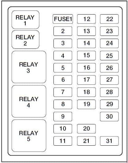
Fuse Box In The Engine Compartment (1999-2001)
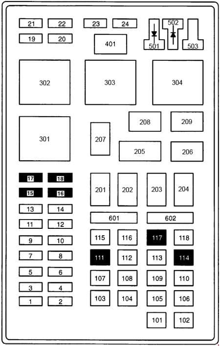
Passenger Compartment Fuse Panel (2002-2005)
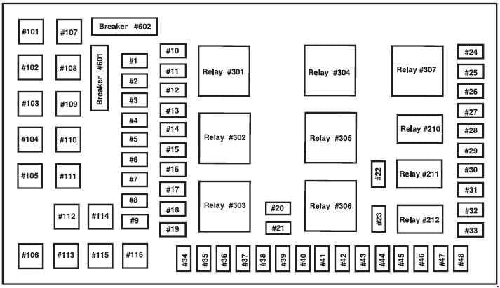
WARNING: Terminal and harness assignments for individual connectors will vary depending on vehicle equipment level, model, and market.
Still have questions or want to supplement the article? Discuss On Telegram
Access the private club
Thank you for your subscription.
We rarely send emails, only the most important moments...
May Be Useful
Ford focus mk3 (2015) - fuse box diagram (usa version), ford focus electric mk3 (from 2015) - fuse box diagram (usa version), ford fiesta (from 2015) - bulb specification (usa version), ford transit courier (from 2015) - fuse box (eu version), ford flex (2008 - 2015) - fuse box diagram (usa version), ford c-max mk2 (2015) - fuse box (vehicles built up to 22-06-2015) - (eu versrion).
2001 Ford Expedition fuse box diagram
The 2001 Ford Expedition has 2 different fuse boxes:
Ford Expedition fuse box diagrams change across years, pick the right year of your vehicle: 2021 2020 2019 2018 2017 2016 2015 2014 2013 2012 2011 2010 2009 2008 2007 2006 2005 2004 2003 2002 2001 2000 1999 1998 1997

Did you find the website helpful?


Fuse box diagrams, fuse layouts and assignment
Ford Expedition (1997-2002) Fuse Diagram
Advertisements
Fuse box diagram (fuse layout), location and assignment of fuses and relays Ford Expedition (1997, 1998, 1999, 2000, 2001, 2002).
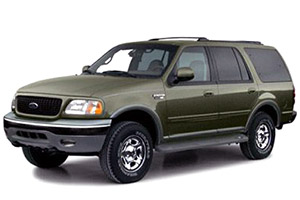
Checking and Replacing Fuses
Fuses and circuit breakers protect your vehicle’s electrical system from overloading. If electrical parts in your vehicle are not working, the system may have been overloaded and blown a fuse or tripped a circuit breaker. Before you replace or repair any electrical parts, check the appropriate fuses or circuit breakers.
To check a fuse, look at the silver-colored band inside the fuse. If the band is broken or melted, replace the fuse.
- Before replacing fuses check that the key has been removed from the ignition and that all the services are switched off and/or disengaged.
- Always disconnect the battery before servicing high current fuses.
- Always replace a fuse with one that has the specified amperage rating. Using a fuse with a higher amperage rating can cause severe wire damage and could start a fire.
- Never replace a broken fuse with anything other than a new fuse. Use always an intact fuse of the same color.
- If a fuse blows again contact a qualified service center.
Passenger Compartment Fuse Box Diagram
The fuse panel is located below and to the left of the steering wheel by the brake pedal. Pull the panel cover outward to access the fuses. To remove a fuse use the fuse puller tool provided on the fuse panel cover.
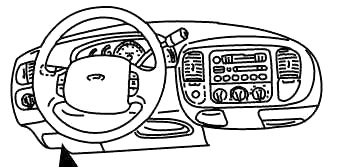
Engine Compartment Fuse Box
The power distribution box is located in the engine compartment. The power distribution box contains high-current fuses that protect your vehicle’s main electrical systems from overloads.
Diagram (Version 1)
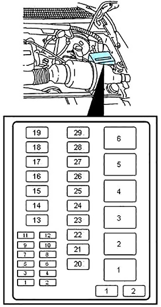
Diagram (Version 2)
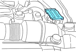
Primary battery fuses (megafuses)
The primary battery fuses are located in the engine compartment near the battery. Ford recommends that a qualified service technician service the mega fuses.
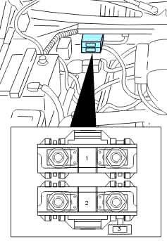
Engine mini fuse box
The engine mini fuses are located on the driver’s side of the engine compartment.
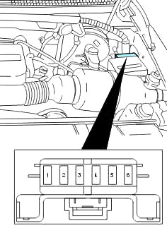
Replace a Fuse: 2001 Ford Expedition Eddie Bauer 5.4L V8
Ford expedition model years - 1997, 1998, 1999, 2000, 2001, 2002.
Find the 2001 Expedition engine compartment fuse block

Hans Angermeier is an ASE certified Maintenance and Light Repair Technician and has produced over 100,000 videos showing drivers how to fix things on their cars. He has broad expertise on basic repair procedures covering the majority of cars on the road. Over the past 10 years, Hans has been focused on building CarCareKiosk, which is visited by millions of drivers each month.
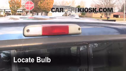
Don't be the guy with your third brake light burnt out
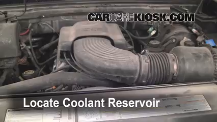
Leaking coolant is usually a sign that your water pump needs to be replaced. This video shows you how to quickly plug it
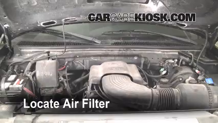
Learn where your air filter is located and how to determine if it needs to be changed.
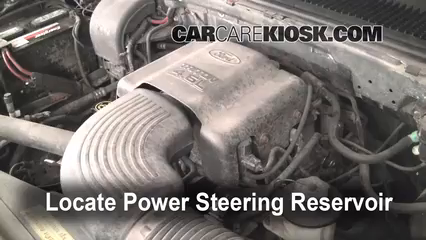
If your car is leaking a small amount of power steering fluid - see this video on how to fix the leak
- Lake Chevy helped make these videos
- Download Ford owners manuals

If your convenience lights, turn signals, seat warmers, stereo, headlights or other electronic components suddenly stop working, chances are you have a fuse that has blown out. The video above shows how to check and change blown fuses in the engine bay of your 2001 Ford Expedition in addition to where the fuse box diagram is located. Fuses should always be the first thing you check if your Expedition is experiencing electrical difficulties because they are relatively easy and inexpensive to change yourself. The more electronics your Expedition has, the more fuses it has. Some Fords have multiple fuse boxes in the engine bay, so be sure to find the fuse(s) in question. Some components may have multiple fuses, so make sure you check all of the fuses that are linked to the component that is no longer working properly. If you need to replace a blown fuse in your Expedition, make sure you replace it with one that has the same amperage as the blown fuse. If checking and replacing the fuse for the component in question doesn't work, we recommend seeking assistance from a trusted professional mechanic. They should be able to figure out if the component needs to be replaced or if there is a short or some other problem with your Expedition.
- Advance Auto coupon for 20% off entire order: KIOSK20
We have a massive and growing video library, but we don't have everything...yet.
Car companies often use the same engines in different cars. They also slightly alter the styling and sell the same car by two different names (amongst other tricks to help offset development costs).
Our system selects the most applicable video for your car based, in part, on these characteristics. The video displayed may not look exactly like your car, but may be relevant enough for you to get a good idea how to do it.
Fuse box diagram
Fuse box diagram Ford Expedition
For the Ford Expedition First generation, 1997, 1998, 1999, 2000, 2001, 2002 model year.
Passenger compartment fuse panel.
fuse box locaton.
The fuse panel is located below and to the left of the steering wheel by the brake pedal. Remove the panel cover to access the fuses. To remove a fuse use the fuse puller tool provided on the fuse panel cover.
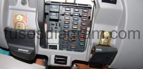
Identifying fuse panel.
Fuse box diagram.
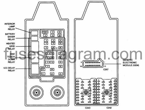
fuse box panel legend.
Power distribution box Ford Expedition.
The power distribution box is located in the engine compartment. The power distribution box contains high-current fuses that protect your vehicle’s main electrical systems from overloads.
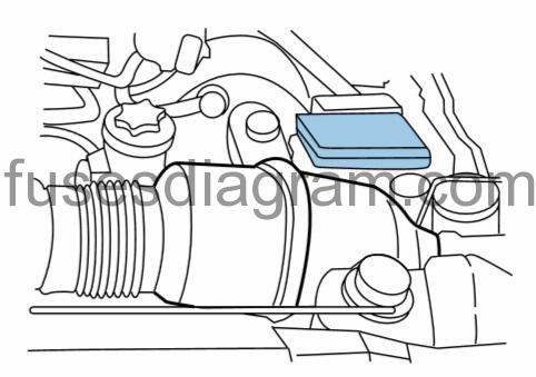
Identifying power distribution box (fuses and releys).
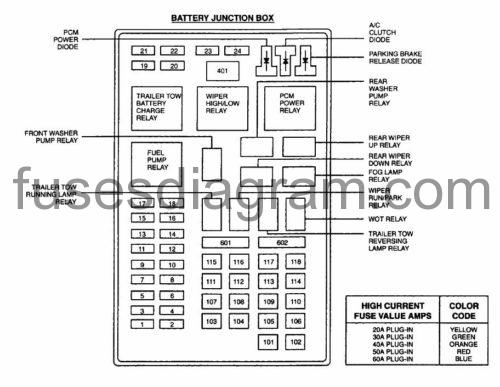
Auto Genius
Ford expedition (1997 – 2002) – fuse box diagram.
Year of production: 1997, 1998, 1999, 2000, 2001, 2002
Passenger compartment
The fuse panel is located below and to the left of the steering wheel by the brake pedal.
The power distribution box is located in the engine compartment
Engine mini fuse box, primary battery fuses.
WARNING: Terminal and harness assignments for individual connectors will vary depending on vehicle equipment level, model, and market.

IMAGES
VIDEO
COMMENTS
Looking for Ford Fuse? We have almost everything on eBay. No matter what you love, you'll find it here. Search Ford Fuse and more.
Shop our full catalog of Genuine OEM Ford Parts and Accessories and save today. Cheapest OEM Ford® Parts & Accessories Online. In stock. Ships Fast. Shop Now and Save!
To check a fuse, look at the silver-colored band inside the fuse. If the band is broken or melted, replace the fuse. Notice. Before replacing fuses check that the key has been removed from the ignition and that all the services are switched off and/or disengaged. Always disconnect the battery before servicing high current fuses.
1999-2000: Not Used. 2001: Ignition Run Power Feed (Customer Access) 28. 15. 1999-2000: Not Used. 2001: DRL, Brake Shift Interlock (BSD, ECM, Overhead Trip Computer (OTC), AUX A/C Components, Hazard Flasher, Speed Control, Vacuum Pump, Backup Lamps, Electronic Shift On The Fly Hublock Solenoid, Heated Seat.
Fuse Layout Ford Excursion 2000-2005. 2000-2001 - is the fuse №3 (Cigar Lighter) in the Instrument panel fuse box, and fuses №7 (Floor Console Auxiliary PowerPoint), №9 (Left Rear Quarter Auxiliary PowerPoint) and №11 (Cargo Auxiliary PowerPoint) in the Engine compartment fuse box. 2002-2005 - fuses №2 (Power point - floor ...
2001 Ford Excursion fuse box diagram. Ford Excursion fuse box diagrams change across years, pick the right year of your vehicle: Type No. Description; Fuse MINI . 20A: 1: Back windshield wiper. Fuse MINI . 15A: 3: Folding quarter window motor.
12-28-2011 11:36 PM. 6. 12-16-2009 07:42 AM. Excursion - King of SUVs - 2001 Excursion 4x4 not working - '01 Excursion 7.3l 4x4. Four wheel drive won't engage, no light on the dash. I've replaced/check all the fuses, replaced the ESOF solenoid, the transfer case motor, the dash switch, and the relays. I can actuate the relays with a power probe ...
Fuse Box Information | Ford Excursion 2001. Ford Excursion 2001 Fuse Box Diagram. Ford Excursion 2001 Fuses, Relays, Location, Fuse Panel, Layout.
See more on our website: https://fuse-box.info/ford/ford-excursion-2000-2005-fuses-and-relayFuse box diagram (location and assignment of electrical fuses and...
More about Ford Excursion fuses, see our website: https://fusecheck.com/ford/ford-excursion-1999-2005-fuse-diagramFuse Box Diagram Ford Excursion (1999, 2000...
Ford Excursion 2001, 12 Volt Accessory Power Outlet Connector by Motorcraft®. Motorcraft is the way to restore the performance of your vehicle. Designed specifically for your vehicle, Motorcraft products meet stringent Ford Motor... Direct OEM replacement Meets strict Ford Motor Company standards. $48.22 - $49.29.
View and Download Ford 2001 Excursion owner's manual online. 2001 Excursion automobile pdf manual download. ... Page 109 Do not attempt to service, repair, or modify the Air Bag Supplemental Restraint System or its fuses. See your Ford or Lincoln Mercury dealer. ... contact your Ford dealer as soon as possible. • 4x4 -momentarily illuminates ...
Ford Excursion (1999 - 2005) Fuse Box Diagram. Jonathan Yarden Jan 25, 2021 · 5 min. read. In this article you will find a description of fuses and relays Ford, with photos of block diagrams and their locations. Highlighted the cigarette lighter fuse (as the most popular thing people look for). Get tips on blown fuses, replacing a fuse, and more.
The fuse panel is located below and to the left of the steering wheel by the brake pedal. Ford F-250 - fuse box diagram - passenger compartment. Number. Ampere rating [A] Description. 1. 20. Turn/Hazard Lamps. 2.
Ford Excursion fuse box diagrams change across years, pick the right year of your vehicle: Type No. Description; Fuse MINI . 15A: 1: Adjustable pedals. Fuse MINI . 20A: 2: Power point - floor console ... Body Security Module (BSM)/4x4 module. Fuse MINI . 10A: 20: Fuel Injection Control Module (FICM) relay [Diesel engine only] Fuse MINI . 25A ...
2001 Ford Expedition fuse box diagram. The 2001 Ford Expedition has 2 different fuse boxes: Passenger compartment fuse panel diagram. ... 4x4 Shift Motor & Clutch. Fuse FMX/JCase . 40A: 105: Climate Control Front Blower. Fuse FMX/JCase -106: Not Used. Fuse FMX/JCase -107: Not Used. Fuse FMX/JCase . 30A: 108:
To check a fuse, look at the silver-colored band inside the fuse. If the band is broken or melted, replace the fuse. Before replacing fuses check that the key has been removed from the ignition and that all the services are switched off and/or disengaged. Always disconnect the battery before servicing high current fuses.
See more on our website: https://fuse-box.info/ford/ford-excursion-2000-2005-fuses-and-relayFuse box diagram (location and assignment of electrical fuses and...
Be cool under pressure. Your coolant should perform well under any condition - just like Aaron Rodgers! 1999 Ford F-150 XLT 4.6L V8 Extended Cab Pickup (4 Door) Change a tail light. The burnt out tail light: classic reason for a cop to pull you over - change yours now. 1999 Ford F-150 XLT 4.6L V8 Extended Cab Pickup (4 Door) Top up the oil level.
Passenger compartment fuse panel. fuse box locaton. The fuse panel is located below and to the left of the steering wheel by the brake pedal. Remove the panel cover to access the fuses. To remove a fuse use the fuse puller tool provided on the fuse panel cover. Identifying fuse panel. Fuse box diagram. fuse box panel legend.
Passenger Compartment Fuse Panel (1999-2001) To remove the fuse panel cover, turn the panel fasteners counter-clockwise. Fuses Specifications No. A Description 1 20 Radio, Secondary Fusing for Audio Options 2 5 Instrument Cluster, Powertrain Control Module (PCM) Keep Alive Memory, PATS LED 3 20
Passenger compartment. The fuse panel is located below and to the left of the steering wheel by the brake pedal. Ford Expedition - fuse box diagram - passenger compartment. №. A. Description. 1. 25. Audio.