Electronic overload relays
Motor protection for overload and phase failure
Main benefits
- Reliable protection for motors
- Easy to create starters
- Optimized match to ABB contactors
- Reduced logistic costs and improved designed by three trip classes in one device
- Single mounting kits and wire reset for remote control available for specific applications
Main features
- Selectable trip class (10E, 20E, 30E)
- Adjustable current setting ranges
- Overload protection with phase loss sensitivity
- Temperature compensation up to +70°C and self supply
- Automatic or manual reset, sealable
- Stop and test function


Are you looking for support or purchase information?

Part of the ABB EcoSolutions TM portfolio
The ABB EcoSolutions™ label provides full transparency on ABB’s progress in embedding sustainability across the entire product lifecycle. To receive the EcoSolutions label, products must carry an independently verified Environmental Product Declaration (ISO 14025 EPD) and meet a range of key performance indicators defined in ABB’s circularity framework. Click HERE to know more about ABB EcoSolutions.
Please ask your ABB contact to provide the correct environmental information for your specific product.

Catalog Motor control and protection for rolling stock
ABB supports the high levels of expectations for safe means of transport.

SOC tool for desktop and tablet
With our Selected Optimized Coordination (SOC) tool, choosing the right solution for your needs couldn’t be easier.

Main catalog Motor protection and control
Our motor protection and control solutions are setting the standard in sustainable performance and reliability.

Panorama for Motor protection and control
Find information and overviews to ease the selection process for the right components to control and protect your motor starting application.

Contactors and motor protection for Railway applications
Find everything you need for a variety of rolling stock applications.

Life cycle status
We help customers to replace the installed low voltage products with the latest or similar models in a matter of hours.
Products and documents browser

Product data

abb.com privacy settings
Our website uses cookies which are necessary for running the website and for providing the services you request. We would also like to set the following optional cookies on your device. You can change these settings any time later by clicking "Change cookie settings" at the bottom of any page. For more information, please read our privacy notice.
We collect statistics to understand how many visitors we have, how our visitors interact with the site and how we can improve it. The collected data does not directly identify anyone.
We store choices you have made so that they are remembered across visits in order to provide you a more personalized experience.
Your browsing behavior is tracked across websites by advertising and social network service providers. You may see tailored advertising and content on other websites based on your browsing profile.
Preferences
Advertising and tracking
Popular links
- ABB Connect
- ABB Electrification
- Where to buy
- Mission to Zero
- ABB Ability
- Supplying to ABB
- Customer events
- Investor events
- Media events
EF Electronic Overload Relay

Motor protection for overload and phase failure Electronic overload relays offer reliable and precise protection for motors in the event of overload or phase failure. The electronic overload relay can make up a compact starting solution together with contactors.
Features and benefits
- Reliable protection for motors
- Easy to create starters
- Optimized match to ABB contactors
- Reduced logistic costs and improved designed by three trip classes in one device
- Single mounting kits and wire reset for remote control available for specific applications.
- Selectable trip class (10E, 20E, 30E)
- Adjustable current setting ranges
- Overload protection with phase loss sensitivity
- Temperature compensation up to +70°C and self supply
- Automatic or manual reset, sealable
- Stop and test function.
Publications
- Application and Technical
- Catalogs and Buyers Guides
- Environmental Product Declaration
- Installation and Instruction
Other Overload Relays IEC

ELECTRICAL CLASSROOM
A complete Electrical Engineering portal
Overload relay – Principle of operation, types, connection
Every motor must be protected from all possible faults to ensure prolonged and safe operation as well as time loss caused due to breakdown. Almost all industries rely on the electric motor to control their processes and production. Hence it is necessary to make the motor fail-safe.
The most vulnerable part of a motor is its winding insulation. The winding insulations are at high risk of damage by excessively high temperatures. Overload relay is one such device that protects a motor from damage caused due to overloads and over-currents. It is used with contactors and can be found in motor control centers and motor starters.
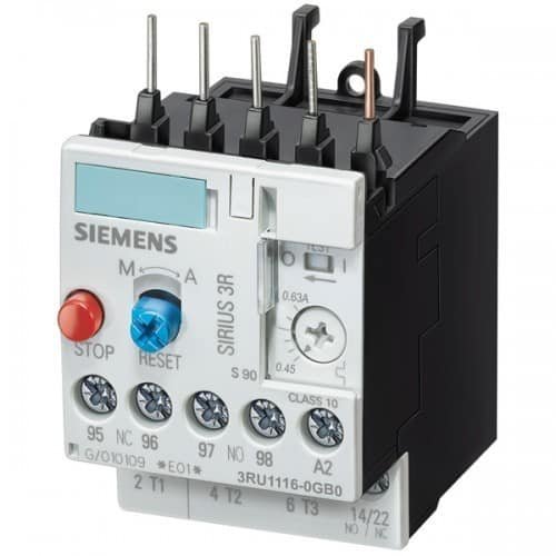
Principle of operation
Types of overload relays, working of bimetallic thermal overload relay, working of electronic overload relay, parts of a thermal overload relay, symbol of an overload relay, frequently asked questions, definition of overload relay.
An overload relay is a device that protects an electric motor against overloads and phase failure.
It senses the overloading of the motor and interrupts the power flow to the motor, thus protecting it from overheating and winding damages. Apart from overloads, it can also protect the motor from phase loss/ failures and phase imbalance . They are very commonly known as OLR .
What is an overload?
An overload is a condition at which a motor draws a current above its rated value, for a prolonged period. (adsbygoogle = window.adsbygoogle || []).push({});
It is the most encountered fault and can result in temperature rise in the motor winding. Hence the rapid return to normal operation is important.
A thermal overload relay works in the principle of electro-thermal properties in a bimetallic strip. It is placed in the motor circuit in such a way that the current to the motor flows through its poles. The bimetallic strip gets heated up by the current directly or indirectly and when the current flow exceeds the set value, it bends.
They always work in combination with contactors. When the bimetallic strips heat up, the trip contact is activated that in turn breaks the power supply to the contactor coil, de-energizing it and breaking the current flow to the motor. This tripping time is always inversely proportional to the current flow through the OLR. Hence higher the current flow faster shall it trips. Therefore, thermal overload relays are referred to as current-dependent and inversely time-delayed relays.
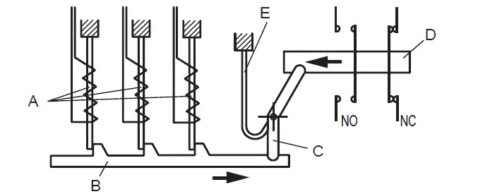
Overload relays can be classified as follows:
- Bimetallic thermal overload relays
- Electronic overload relays
The working principle of the above differs a little from each other. Let us discuss it in the following sections.
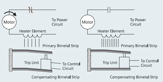
As explained above, a bimetallic thermal relay works on the heating property of the bimetallic strip. In the direct heating method, the full current to the motor flows through the OLR. Therefore, it gets heated up directly by the current.
But in the case of indirect heating, the bimetallic strip is held in close contact with the current-carrying conductor inside the OLR. Excessive current flow to the motor heats up the conductor and hence the bimetallic strip. The conductor shall be insulated hence no current flow through the strip.
Electronic overload relays do not have a bimetallic strip inside. Instead, it uses temperature sensors or current transformers to sense the amount of current flowing to the motor. It uses microprocessor-based technology for protection. Temperature is sensed using PTC and the same is used to trip the circuit in case of overload faults. Some electronic overload relays come with current transformers and Hall effect sensors that directly sense the amount of current flow.
The major advantage of electronic OLR over thermal OLR is that lack of bimetallic strip results in low heat losses inside the relay. Also, Electronic relays are more precise than thermal relays. Some manufacturers build electronic relays with extensive features such as earth fault protection, motor stall protection, etc. Electronic overload relays are much suited for applications that require a frequent start and stop of motors.
In addition, manufacturers offer built-in RTD or thermocouples that can be directly used to measure the winding temperature. These measurements can be used for more accurate thermal overload protection.
They are designed in such a way to withstand the starting current (which is typically 6 to 10 times the full load current) of the motor for a limited period (typically 15-30 seconds depending on the threshold of current).
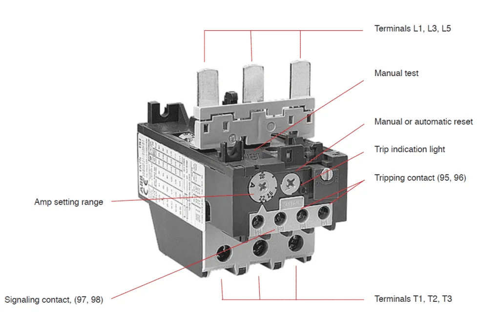
Apart from the bimetallic strip and contacts discussed in the working principle section above, there are a few more parts in an overload relay that needs to be understood.
Terminals L1, L2, and L3 are input terminals. It can be directly mounted to the contactor. Supply to the motor can be connected to Terminals T1, T2, and T3.
Ampere range setting
A rotary knob is present over the overload relay. Using this knob, the rated current of the motor can be set. The current can be set between the upper and lower limits provided. In the case of an electronic overload relay, an additional knob for tripping class selection is also provided.
Reset Button
A reset button is present over the overload relay to reset the overload relay after a trip and clearance of fault.

Manual/Auto reset selection
With the manual/auto reset selection button, we can choose between manual and automatic reset of these relays after a trip. If the device is set to auto, a remote reset of OLR is possible.
Auxiliary contact
They are provided with two auxiliary contacts – one NO (97-98) and another NC (95-96). NO contact is for trip signaling and NC contact is for disconnecting the contactor. NC contacts should be capable of direct switching of contactor coil.
Test button
Using the test button, it is possible to test the control wiring.
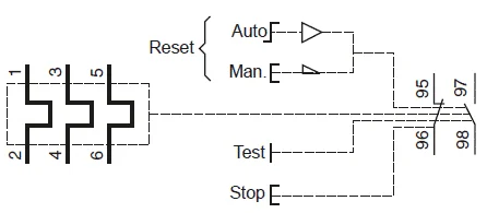
Here 1, 2, 3, 4, 5 and 6 are power terminal 95 & 96 are trip contacts and 97 & 98 are signaling contacts. Learn how to use them in a circuit here: Star-Delta starter wiring diagram – Control and power wiring diagrams
What is the trip Class of overload relay?
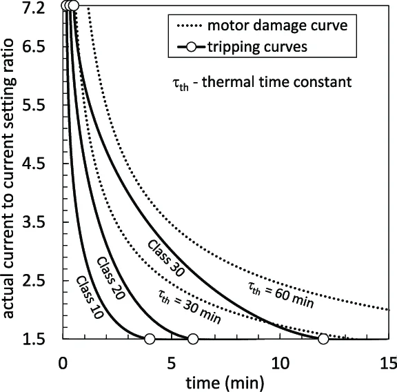
The time taken by them to open the contactor during overloads is specified by the trip class . It is commonly classified into Class 10, Class 20, Class 30, and Class 5. The OLR trips in 10 seconds, 20 seconds, 30 seconds, and 5 seconds respectively at 600% of full load current to the motor.
Class 10 and Class 20 are very commonly used ones. Class 30 overload relays are used for the protection of motors driving high inertia loads and Class 5 relays are used for the motors requiring very fast tripping.
How to use an overload relay in a circuit?
They are always used in combination with the contactors in the circuit. It is connected in line with the motor such that the current to the motor fully flow through it. Below are the various types of connections for single-phase and three-phase motors.
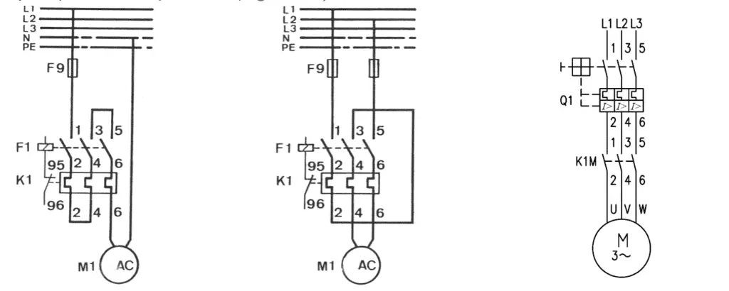
Read more: Sizing of contactor and overload relay for 3 Phase DOL starter Read more on star delta starters: Star-delta starter (Wye-Delta Starters) – Circuit, working . Read more about contactors: Contactor – Construction, Operation, Application and Selection
What causes the OLR trip?
As discussed above, there are three major conditions for overload trips :
- Overloading of the motor.
- Input phase loss
- Phase imbalance.
Apart from these, there may be some additional protection features available. This varies from one manufacturer to the other.
How does an overload relay protect from phase failures?
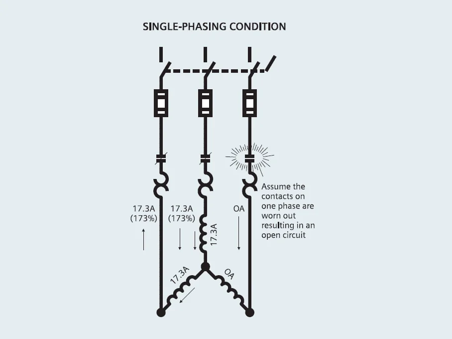
During normal operation, the current flowing through each pole of an overload relay to the motor remains the same at a time. If anyone of the phase is interrupted, the current through the other two phases rises to 1.73 times the normal value. Hence the overload relay gets heated up and it trips. Phase failure is also known as single phasing of motor or phase loss.
Can OLR protect from short circuits?
Overload relays cannot protect against short circuits. They should always be used with short circuit protection devices. Otherwise, any short circuits in the motor can potentially damage them. They can protect against overloads, phase loss, and phase imbalance, but not short circuits.
What could damage an overload relay?
The device will be damaged if the backup short circuit protection device (circuit breaker or fuse) is overrated. This may also damage the whole starter and even the motor windings themselves. Therefore it is advised to stick on to the maximum short circuit protection advised by the relay manufacturer.
An overload relay is a device that can protect a motor from overloads, phase failure, and phase imbalances. Based on the principle of operation they are classified into thermal and electronic overload relays. Thermal OLR is based on the principle of deformation of a bimetallic strip on heating. The electronic overload relay is a microprocessor-based device and comes with extensive built-in functionalities.
OLRs are used in combination with the contactors. It opens the contactor whenever it senses a fault. The time taken by them in opening the contactor during overloads is specified by their trip class. Overload relays cannot protect against short circuits. This sample datasheet can help you understand the relay ratings. They could be easily damaged if underrated or under with an overrated short circuit protection device (Fuse or Circuit breaker).
Related articles
Relay – Operation, types and applications
Difference between NO and NC
Difference between electromechanical relays and solid-state relays
Difference between earth leakage relay and earth fault relay
Buchholz Relay – Working Principle, Construction and Operation
Difference between contactors and relays
2 thoughts on “Overload relay – Principle of operation, types, connection”
Excellently described. Brief, to the point and comprehensive text.
Leave a Comment Cancel reply

- Get custom product tools and services
- Access training
- Manage support cases
- Create and manage your orders (authorized partners only)
Schneider Electric USA Website
Search FAQs
What does the trip class 10, class 20 and class 30 mean for overload relays.
Article available in these languages: Czech , Spanish , Hungarian , Romanian
Released for: Schneider Electric USA
Discuss this topic with experts
Start here!
Find answers now. Search for a solution on your own, or connect with one of our experts.
Contact Support
Reach out to our customer care team to receive more information, technical support, assistance with complaints and more.
Where to buy?
Easily find the nearest Schneider Electric distributor in your location.
Search topic-related frequently asked questions to find answers you need.
Contact Sales
Start your sales inquiry online and an expert will connect with you.

Overload or Thermal Protection (ANSI 49)
Introduction
Overload or thermal protection protects all types of motor applications against overload currents.
Operating Principle
Overload or thermal protection is I 2 t IDMT (Inverse Definite Minimum Time):
o It incorporates the motor thermal image function.
o It can be configured as the Ir pickup and as the trip class (Class).
Tripping curve:
Ir Pickup Setting Value
The overload or thermal protection pickup (Ir) is set by using a multi-position dial.
The default Ir pickup setting value is 0.4 x In (minimum dial value).
The overload or thermal protection tripping range is 1.05–1.20 x Ir according to IEC/EN 60947-4-1 standard.
The following table shows the preset values of the adjustment dial Ir in amperes for each current rating In:
Trip Class Setting Value
The trip class (Class) is set by using an adjustment dial:
o Class 10 (default value)
The trip class corresponds to the value of the tripping time for a current of 7.2 x Ir according to IEC/EN 60947-4-1 standard.
The following table shows the value of the tripping time depending on the current in the load for all three classes:
The precision range is -20%, + 0%
Motor Thermal Image
The model representing heat rise and cooling in a motor load is constructed according to the algorithm for calculating the thermal demand, taking account of the iron and copper losses.
The following figure represents the limit curves for the iron and copper components calculated for class 20:
Thermal Memory
The trip unit uses a thermal memory function to protect the motor from overheating in case of low amplitude repetitive faults.
Electronic protection without thermal memory function does not protect against repetitive faults because the duration of each overload above the pickup setting is too short to cause tripping. However, each overload causes a temperature rise in the installation. The cumulative effect of successive overloads can overheat the system. The thermal memory function remembers and integrates the thermal heating caused by each pickup setting overrun. The thermal memory function remembers the thermal heating values for 20 minutes before or after tripping.
Example: Comparison of the heat rise calculation without thermal image (diagram A ) and with thermal image (diagram B ):
With thermal image, the trip unit adds the thermal effect of successive current pulses. Tripping occurs based on the actual thermal state of the motor.
Cooling Fan
The thermal image of the motor is calculated taking account of the fact that the motor is self-cooled (fan mounted on the shaft end).
DOCA0161EN-01
© 2020 Schneider Electric. All rights reserved.
- Site Search Search Posts Find A Forum Thread Number Threads by Name Search FAQs
- ENGINEERING.com
- Eng-Tips Forums
- Tek-Tips Forums

Join Eng-Tips ® Today!
Join your peers on the Internet's largest technical engineering professional community. It's easy to join and it's free.
Here's Why Members Love Eng-Tips Forums:
- Notification Of Responses To Questions
- Favorite Forums One Click Access
- Keyword Search Of All Posts, And More...
Register now while it's still free!
Already a member? Close this window and log in.
Join Us Close

IMAGES
VIDEO
COMMENTS
Introduction. The E100 Electronic Overload Relay is the next generation basic-tier electronic overload relay. It has enhanced features to better safeguard your motor protection investments, including increased accuracy and repeatability, a self-powered design with lower heat dissipation, and the certifications to comply with many applications.
This chapter provides instructions about how to operate and configure an E100TM Electronic Overload Relay system. It includes instructions about how to set the Trip Current and Trip Class. This chapter also describes the accessory modules that are available for the Advanced (193/592-1EF) E100 relay.
Trip classes according to NEMA. NEMA Standard MG-1 defines 4 types of Classes. The most common classes are 5, 10, 20 & 30. Class 5, 10, 20 & 30 overload relays will trip within 5, 10, 20 & 30 seconds respectively at 600% of motor full load amps. A Class 10 overload relay, for example, has to trip the motor offline in 10 seconds or less at 600% ...
Electronic Overload Relays class 10, 20, 30 Catalog number Setting range Trip class List price Contactor Suffix code Trip Class 10 E16DU0.32-10 0.1-0.32A 10 ... Description Contactor Setting range Trip class Catalog number List price UMC22-FBP. A9 - AF1650 0.63 - 63 A 5, 10, 20, 30 1SAJ510000R0400 $ 689.50 Universal Motor Controller
The E200 overload relay is part of the E300 product portfolio and is configurable using the Connected Components Workbench software. The E200 relay features a single Type B USB interface port, three rotary dials to set the FLA for the application, and an 8-position DIP switch for trip class and feature selection.
Electronic overload relays EF460 and EF750. Data sheet. Description - Overload protection - trip class 10E, 20E, 30E selectable - Phase loss sensitivity - EF750Temperature compensation from -25 … +70 °C - Adjustable current setting for overload protection - Automatic or manual reset selectable - Trip-free mechanism - Status ...
Electronic overload relays offer reliable and precise protection for motors in the event of overload or phase failure. The electronic overload relay can make up a compact starting solution together with contactors. ... Selectable trip class (10E, 20E, 30E) Adjustable current setting ranges; Overload protection with phase loss sensitivity ...
Selectable trip class (10E, 20E, 30E) Adjustable current setting ranges Overload protection with phase loss sensitivity Temperature compensation up to +70°C and self supply Automatic or manual reset, sealable ... Electronic overload relays offer reliable and precise protection for motors in the event of overload or phase failure. The ...
Electronic overload relay EF19 and EF45 Electronic overload relays offer reliable protection in case of overload and phase-failure. They are the alternative for overload protection to thermal overload relays. Motor starters are combinations of overload Description • Overload protection - trip class 10E, 20E, 30E selectable
Selectable trip class (10A, 10, 20, 30) Direct mounting to NEMA, IEC, and DP contactors Most compact electronic overload in its class Motor Control Two B600 alarm (NO) and fault (NC) contacts Test/Trip button Motor Protection Thermal overload Phase loss Selectable (ON/OFF) phase unbalance Selectable (ON/OFF) ground fault User Interface
Adjustable trip classes (IEC Class 10A; NEMAT Class 10, 20 and 30). Ground fault versions have only NEMA Class 10 and 20. Selectable (ON/OFF) phase and ground fault protection. Can be fitted with electronic remote reset/ communication modules for easy competitive retrofit. Predictive indication The C440 and XT electronic overload relays are ...
Class 10 tripping characteristics. The CEP7-1EE Basic model is equipped with dip switches that allow the select ability between Class 10 and Class 20, while the CEP7-1EF Advanced model possesses a selection dial on the face of the overload for trip classes 10/15/20 and 30. This selection feature allows you to closely match the Trip Class with the
Trip Class Designation Regardless of the product style (NEMA or IEC), overload relays respond to overload relay conditions according to trip curves. These trip curves are defined by the class of protection required (see Table 1). Table 1: Trip Classes Class Designation q Tripping Time Class 10 10 Seconds or less Class 20 20 Seconds or less
The E100 basic model has two user-adjustable trip class settings of 10 and 20. Optional accessories and expansion modules can extend the functionality of the E100 overload relays, enhancing motor overload protection while maintaining a cost-effective solution. The E100 is part of a comprehensive motor protection relay portfolio to provide you ...
Direct mounting to the left side of the 193-EE and 592-EE E1 Plus overload relays means that only 18 mm is added to the overall product width. The side-mounted accessory modules electronically interface with the E1 Plus overload relay so that all control circuit connections are made at the E1 Plus overload relay terminals.
If a lower trip class is used, the OL will trip far too often. Some overload relays are purchased with a fixed trip class. Others have configurable trip classes using switches to use for all sorts of situations. Each facility will need a different trip class depending on its application (e.g., assembly lines and conveyors, robots and AGVs, ASRS ...
CLASS TRIP.33.66 1.0 1.32 1.65.33.66 1.0 1.32 1.65. Scan Product QR code for Product Information. Phase Imbalance Selection. Unit status LED. Motor is running. Current < 1.15 Times Dial Seeting. 1 Flash/ 2 Seconds Motor is running. Current ≥ 1.15 Times Dial Seeting. 2 ˚ash/ 2 seconds if the orange trip ˚ag is visable, a trip has occurred ...
What is the trip Class of overload relay? The time taken by them to open the contactor during overloads is specified by the trip class. It is commonly classified into Class 10, Class 20, Class 30, and Class 5. The OLR trips in 10 seconds, 20 seconds, 30 seconds, and 5 seconds respectively at 600% of full load current to the motor.
Issue: Meaning of Trip Classes for overload relays. Product Line: NEMA Overload Relays Environment: North American Products Resolution: The trip class means that at 600% (6 times) of the maximum thermal current rating (or 600% of the actual dial setting on adjustable overloads) the Class 10 will trip in 10 seconds or less, Class 20 will trip in 20 seconds or less, and Class 30 will trip in 30 ...
The overload or thermal protection pickup (Ir) is set by using a multi-position dial. The default Ir pickup setting value is 0.4 x In (minimum dial value). The overload or thermal protection tripping range is 1.05-1.20 x Ir according to IEC/EN 60947-4-1 standard. The following table shows the preset values of the adjustment dial Ir in amperes ...
condition. The most common trip classes are Class 10, Class 20, and Class 30. A Class 10 overload relay, for example, has to trip the motor offline in 10 seconds or less at 600% of the full load amps (which is usually sufficient time for the motor to reach full speed). Many industrial loads, particularly high inertia loads, require Class 30 ...
Quite often we here of applications in which the motor protection/overload relay 'trips' during normal motor starting. The remedial action taken by many when faced with this problem is to select and install a replacement overload relay, generally one that provides a higher 'Trip Class' setting, for example, Trip Class 20 in lieu of the standard Trip Class 10.
PT = t. tot The electronic overload relay simulates the thermal behaviour of a motor in a model. The tripping threshold of the overload relay is situated at (1.125 ± 0.075) x rated current. The temperature of the motor can have the following characteristics, when it gets started frequently.