
Sensor Guides

Map Sensors 101: A Beginner’s Guide to Understanding Engine Management Systems

Unraveling the Mysteries of Engine Management Systems with Map Sensors 101
In the vast realm of automotive technology, understanding the intricacies of engine management systems is crucial for any enthusiast or aspiring mechanic. In this comprehensive guide, we delve into the heart of these systems, focusing on the pivotal role of map sensors. Let’s embark on a journey to demystify the complexities and empower you with knowledge. Buckle up for Map Sensors 101!
Navigating the Landscape: A Primer on Map Sensors
Map sensors, short for Manifold Absolute Pressure sensors, serve as the linchpin in modern engine management. These sensors measure the pressure within the intake manifold, providing vital data to optimize fuel delivery and ignition timing. Whether you’re a novice or an aficionado, grasping the fundamentals of these sensors is key to unlocking the full potential of your vehicle’s performance.
The Essentials Unveiled – How Map Sensors Work
- To comprehend the functioning of map sensors, envision them as the eyes of your car’s engine.
- These sensors gauge the pressure of the air entering the manifold, aiding in calculating the air density.
- The data acquired enables the engine control unit (ECU) to make real-time adjustments to fuel injection and ignition timing.
Evolution of Map Sensors: A Journey Through Generations
As automotive technology advances, so do map sensors. From the early days of analog systems to the sophisticated digital sensors of today, understanding the evolution is crucial. Let’s traverse through time and witness the metamorphosis of map sensors, shaping the landscape of engine management.
Analog Antecedents – The Genesis of Map Sensors
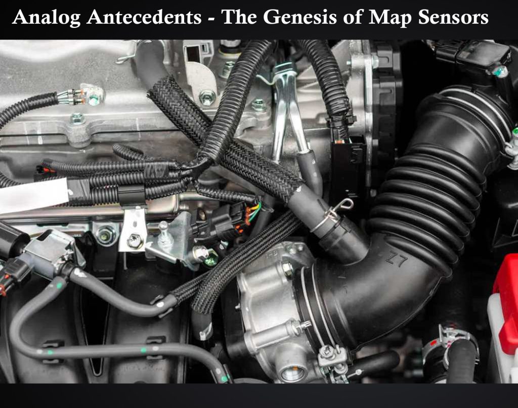
- In the analog era, map sensors were rudimentary devices, translating pressure changes into electrical signals.
- Despite their simplicity, these sensors laid the foundation for the precision we now demand in engine management.
Digital Renaissance – The Modern Map Sensor Era
- With the advent of digital technology, map sensors evolved into highly accurate, responsive components.
- Microprocessors within these sensors process information swiftly, providing instantaneous feedback to the ECU.
Applications and Implications – Where Map Sensors Rule
Map sensors aren’t confined to a single realm; their influence extends across various automotive applications. Understanding these diverse applications is instrumental in appreciating the widespread impact of map sensors on engine management.
Performance Tuning Precision
- Enthusiasts and professionals utilize map sensors for fine-tuning engines, achieving optimal performance levels.
- Precision adjustments to air-fuel ratios and ignition timing lead to enhanced power output and fuel efficiency.
Fuel Efficiency Frontiers
- Map sensors play a pivotal role in fuel-efficient engine management, optimizing combustion for better mileage.
- Eco-conscious drivers and automakers alike rely on these sensors to strike the delicate balance between power and efficiency.
Troubleshooting Chronicles – Map Sensor Issues and Resolutions
Despite their critical role, map sensors can face challenges that impact engine performance. Let’s explore common issues and effective resolutions, empowering you to troubleshoot and keep your engine running at its peak.
The Culprits Behind Poor Performance
- Dirty or faulty map sensors can lead to inaccurate pressure readings, causing erratic engine behavior.
- Wiring issues or connector malfunctions may disrupt the communication between the sensor and the ECU.
Rescuing Your Ride – Map Sensor Maintenance Tips
- Regular cleaning and inspection of map sensors can prevent debris buildup, ensuring accurate readings.
- Checking wiring and connectors for signs of wear or corrosion is a proactive measure to ward off potential issues.
Future Horizons – Innovations in Map Sensor Technology
As technology continues its relentless march forward, what does the future hold for map sensors? Delve into the cutting-edge advancements and emerging technologies that promise to redefine engine management in the years to come.
Smart Sensors and AI Integration
- The integration of artificial intelligence with map sensors opens new frontiers in adaptive engine management.
- Smart sensors analyze intricate data patterns, continuously optimizing performance based on driving conditions.
Environmental Consciousness – Map Sensors in Green Automotive Initiatives
- Map sensors play a vital role in eco-friendly automotive solutions, contributing to cleaner emissions and sustainable driving practices.
- Innovations such as sensor-enhanced catalytic converters showcase the commitment to environmental responsibility.
Embark on Your Map Sensors Odyssey: Mastering Engine Management Systems
In conclusion, understanding the nuances of map sensors is not just a journey through the intricacies of engine management but a mastery of automotive prowess. Whether you’re an amateur enthusiast or a seasoned mechanic, this guide equips you with the knowledge to navigate the complexities of map sensors and elevate your understanding of engine management systems. Embark on this odyssey, and let the road to automotive expertise unfold before you.

Welcome to my author page! I'm Liam Plunket, an expert mechanic and the proud owner of a reputable car repair shop. But I'm not just about fixing cars—I also have a passion for storytelling. This page is where my two worlds collide, combining my automotive expertise with captivating narratives. Join me on this literary journey as I share my experiences, insights, and adventures through the written word. From thrilling tales of automotive triumphs to practical tips and advice for car enthusiasts, I invite you to explore the fascinating world of cars through my unique perspective. Get ready for a blend of mechanical mastery and storytelling magic. Together, let's embark on an exciting literary ride!
Similar Posts

Ever Wondered How Your Car Knows What to Do? Delving into the Map Sensor Magic!
Unlocking the Mysteries of Map Sensor Technology: A Deep Dive into Your Car’s Brain Map Sensor Magic Unveiled! Ever Wondered How Your Car Knows What to Do? Delving into the Map Sensor Magic! Navigating the Terrain of Map Sensors and Their Crucial Role in Automotive Functionality The intricate dance of technology within your car involves…

Unraveling the Mystery: What Exactly is a Map Sensor and Why Does Your Car Need It?
Unraveling the Mystery: Decoding the Significance of a Map Sensor in Your Vehicle In the complex world of automotive technology, one component stands out in its importance – the Map Sensor. As a car owner or enthusiast, understanding this integral part of your vehicle can unlock a deeper comprehension of its functioning. Join us on…

How Does a Map Sensor Revolutionize Engine Performance?
Unlocking the Power of a Map Sensor for Optimal Engine Performance In the realm of automotive innovation, one component stands out as a true game-changer: the Map Sensor. [How Does a Map Sensor Revolutionize Engine Performance?] This article delves into the intricacies of this vital device, exploring its functions, benefits, and impact on overall engine…
Leave a Reply Cancel reply
Your email address will not be published. Required fields are marked *
Save my name, email, and website in this browser for the next time I comment.

What is the MAP sensor of your G5?
In short: The MAP sensor is the sensor that measures the pressure of the intake manifold, also called inlet manifold, of the engine (the part where the air comes in). If it gets damaged, you should replace it , because it cannot be fixed. The acronym MAP stands for Manifold Absolute Pressure.
The MAP sensor is next to the butterfly valve, and it is usually attached to its structure or to the intake manifold. This sensor is small, and its parts are immovable. It has a small hose that is placed in a hole that leads to the inside of the air circuit.
To function, the engine always tries to draw air in, but the butterfly valve blocks it partially. This creates a depression (a “negative” pressure) inside the intake manifold. It is like sucking the air in an empty plastic bottle. The faster the engine spins, and/or, the tighter this butterfly valve is closed, the bigger this depression will get. With this and some other pieces of information, the ECU (Electronic Control Unit) estimates the engine load (the burden placed on the engine) and adjusts the fuel injection to keep its optimal performance and minimize its fuel consumption.
Signs that show that your G5‘s MAP sensor is faulty
- The Check engine light comes on
- Erratic speed: sometimes you cannot speed up, the acceleration may be slow, or your car may decelerate
- Increased smoke emissions
⚠️ Some other problems may cause symptoms similar to those of a faulty MAP sensor , for example, vacuum leaks. For this reason, it is important to examine the vacuum circuit breaker before you change this sensor. ⚠️ If the MAP sensor gets damaged, you need to replace it because it cannot be fixed.
Related guides
Pontiac g5 problems: the map sensor.
Did you find the website helpful?


- Supermercado
- Mercado Play Grátis
- Também pode te interessar
- sensor map fox
- sensor map gol g5
- sensor temperatura gol g6
- sensor map gol g2
- sensor map gol g3
- sensor map gol g4
Sensor Map Vw Gol G3/g4/g5/g6 Voyage G5/g6 0261230235
em 5x R$ 31 , 40 sem juros
Frete grátis
Saiba os prazos de entrega e as formas de envio.
Devolução grátis
Você tem 30 dias a partir da data de recebimento.
Estoque disponível
MercadoLíder | +5mil vendas
Compra Garantida Vai abrir em uma nova janela , receba o produto que está esperando ou devolvemos o dinheiro.
MercadoLíder Gold
Vendas concluídas
Ofereça um bom atendimento
Entrega os produtos dentro do prazo
Você tem 30 dias a partir do recebimento do produto para devolvê-lo, não importa o motivo!
- Meios de pagamento
Pague em até 7x sem juros !
Até 12x sem cartão de crédito
Cartões de crédito
Cartões de débito
Boleto bancário
Características do produto
Características principais.
**DESCRIÇÃO DO PRODUTO Sensor Map Vw 0261230235 03C906051F Bosch Original **APLICAÇÃO Fox 2003 até 2014 SpaceFox 2006 até 2014 CrossFox 2006 até 2014 Gol G3/G4/G5/G6 2003 até 2016 Voyage G5/G6 2009 até 2016 Saveiro G5/G6 2009 até 2016 Golf 2002 até 2013 Jetta 2.5 2005 a 2010 Jetta 2011 Jetta Variant 2008 Em Diante Passat Variant 2009 À 2011 Polo 2003 À 2014 Touareg 2011 Em Diante Kombi 2006 até 2012 New Beetle 2003 até 2010 **CARACTERÍSTICAS Pinagem: 4 pinos Procedência: Original Bosch Referência: 0261230235 03C906051F **ITENS INCLUSOS: 1 Sensor MAP Bosch VW **SKU: 0261230235 *Somos a OPEN Auto Peças, Mercado Líder Platinum com mais de 100.000 vendas realizadas e alto índice de satisfação. *Oferecemos peças de qualidade, originais e paralelas. *Despachamos todos os pedidos com pagamentos confirmados até às 11 horas do mesmo dia útil. *Todas as vendas acompanham Nota Fiscal. *Garantia de 3 meses. *IMPORTANTE: NÃO nos responsabilizamos pela má instalação ou mau uso do produto. Para evitar transtorno procure um PROFISSIONAL ESPECIALIZADO. *ANTES de efetuar sua compra retire todas as dúvidas. *COMPRE SOMENTE SE A PEÇA FOR DA MESMA NUMERAÇÃO OU CARACTERÍSTICAS. Garantia do vendedor: 90 dias
Perguntas e respostas
Qual informação você precisa.
- Custo e prazo de envio
- Devoluções grátis
Pergunte ao vendedor
Últimas perguntas feitas
Opiniões do produto.
Avaliação 5 de 5
20 avaliações
Opiniões em destaque
Top recomendo.
Funcionou certinho.
Produto top.
Anúncio #1244794347
Mais informações
- Mercado Livre
- Investor relations
- Sustentabilidade
Outros sites
- Desenvolvedores
- Mercado Pago
- Mercado Shops
- Mercado Ads
- Solução de problemas
Redes sociais
Minha conta, assinaturas.
- Deezer Premium
Usamos cookies para melhorar sua experiência no Mercado Livre. Consulte mais informações na nossa Central de privacidade.

- Forum Listing
- Marketplace
- Advanced Search
- Engine & Gearbox
MAP Sensor fault 2.5 TDI ACV - HELP!!!
- Add to quote
Hi all My van felt sluggish so I read the fault codes and came up with: 17563 Manifold Pressure Sensor (G71): Short to Plus 17565 givers for suction tube pressure -G71 supply voltage It's not the sensor as we've changed that, thought it could be a break in the wire from sensor to/from ECU so checked voltages on wires 3 and 4 according to wiring diagram (4 pin sensor) 5V going into sensor on wire 3 (red/green) - from what I understand this is the feed to the sensor from the ECU which is correct 1.9V when idling out of sensor at wire 4 (blue/black) - from what I understand this voltage is adjusted by the sensor dependant on reading and is read by the ECU? This voltage lowers slightly if a boost pipe is squeezed to change pressure near the sensor. Thought the blue/black wire may have been broken but checked the voltage at the wires going into the ECU and it was the same so now I'm stuck, was hoping for an easy fix with a broken wire. Am I doing understanding this correct or not? Is the voltage coming out of sensor too high? Did a data run and logged it, any pointers greatly appreciated guys, getting really bored with flying past HGV's going down hills then them catching me up on the other side! Monday 2 September 2013 20:57:56 074 906 018 B 2.5l R5 EDC 0000SG 2519 Group A: '003 Group B: '008 Group C: '011 RPM Mass Air / Rev. Mass Air / Rev. Duty Cycle RPM Inj. Quantity Inj. Quantity Inj. Quantity RPM Absolute Pres. Absolute Pres. Duty Cycle TIME TIME TIME Marker STAMP /min mg/str mg/str % STAMP /min mg/str mg/str mg/str STAMP /min mbar mbar % 1.07 1367 850 455 4.8 0.35 1265 40.4 28.4 21.6 0.71 1326 1397.4 1020 68.1 2.15 1510 850 465 4.8 1.43 1428 41 31.6 22 1.79 1469 1489.2 1020 68.1 3.23 1673 850 480 4.8 2.51 1571 40.2 33.6 22.2 2.87 1632 1570.8 1020 68.1 4.3 1836 850 485 4.8 3.59 1734 39.4 34.8 22.8 3.94 1795 1672.8 1020 68.1 5.38 2020 850 505 4.8 4.66 1918 38.6 36.4 22.2 5.02 1958 1744.2 1020 68.1 6.47 2203 850 520 4.8 5.74 2060 38.2 37.4 23.4 6.1 2122 1734 1020 68.1 7.54 2387 850 530 4.8 6.82 2244 37.8 37.8 24.4 7.18 2326 1703.4 1020 68.1 8.62 2550 850 540 4.8 7.9 2448 37.4 38 25 8.26 2509 1672.8 1020 68.1 9.7 2713 850 540 4.8 8.98 2611 37 38.4 25.4 9.34 2652 1662.6 1020 68.1 10.76 2876 850 565 4.8 10.06 2774 36.8 38.8 26 10.39 2815 1652.4 1020 68.1 11.84 2999 850 560 4.8 11.12 2897 36.6 39 26.4 11.48 2958 1642.2 1020 68.1 12.92 3121 850 570 4.8 12.21 3040 36.4 39.2 26.8 12.56 3080 1642.2 1020 68.1 14 3244 850 575 4.8 13.28 3162 36.2 39 27.6 13.64 3203 1632 1020 68.1 15.08 3346 850 575 4.8 14.36 3284 36 38.8 27.8 14.72 3305 1632 1020 68.1 16.15 3448 850 575 4.8 15.44 3386 36 38.4 27.6 15.79 3407 1621.8 1020 68.1 17.22 3529 850 575 4.8 16.52 3488 35.8 38.2 28 16.86 3488 1621.8 1020 68.1 18.3 3611 850 585 4.8 17.58 3570 35.6 37.8 27.4 17.94 3590 1611.6 1020 68.1 19.38 3692 850 575 4.8 18.66 3652 35.2 37.4 26.6 19.03 3672 1611.6 1020 68.1 20.46 3754 850 575 4.8 19.74 3733 35 36.6 26.8 20.1 3733 1601.4 1020 68.1 21.54 3835 850 570 4.8 20.82 3794 34.8 36.2 27.4 21.18 3815 1601.4 1020 68.1 22.62 3896 850 575 4.8 21.9 3856 34.6 35.2 26.8 22.26 3876 1591.2 1020 68.1 23.7 3958 850 560 4.8 22.98 3917 34.4 34.6 26.4 23.34 3917 1591.2 1020 68.1 24.78 3998 850 560 4.8 24.06 3958 34.4 34.2 26 24.42 3978 1591.2 1020 68.1 25.86 3774 850 455 4.8 25.14 3937 0 34.2 25.4 25.51 3917 1152.6 1020 68.1 26.93 3223 640 455 4.8 26.22 3611 0 37.6 18.2 26.58 3427 1132.2 1020 68.1 28 2958 400 450 13.9 27.29 3040 0 39.2 19.4 27.66 2999 1122 1020 68.1 29.08 2652 335 455 47 28.36 2876 0 39 19.4 28.72 2774 1111.8 1020 68.1 30.16 2244 290 450 94.4 29.44 2530 0 38.2 19.6 29.8 2366 1091.4 1020 68.1 31.24 2020 290 445 94.4 30.52 2162 0 37.6 19.6 30.88 2122 1081.2 1020 68.1
Sorry, didn't insert the data properly No code has to be inserted here.
I would say by looking at the mass air rev. and absolute pres. readings, one being specified and one being actual, that you have an air leak. If you have the original pipework check the joints that are held in with the clips, don't worry too much about the clip but check the male piece of pipe, they have two humps that the clip locks into, they wear down and allow the pipe to move slightly and leak when under boost to start with. check the pipes before getting stuck in tugging at the pipes, you may see one that is not fully home and by fully home i mean ......the pipes when together should but up 100% flush, if not check that one first. if you have a helper, you can try getting them to rev the engine till the turbo kicks in, you may just hear it but it may not be enough boost to re-create the leak! take care when doing this and keep hands etc away the sluggishness your getting could be limp mode if the dash has the DTC light on?
Am I right that the second column is actual pressure, and is constant at 1020mbar? If this is the case, then the sensor is recieving no pressure change, the sensor is faulty, or as the fault code suggests, there is a wiring fault. Is the sensor mounted directly onto the boost pipework? (not remotely via a small bore tube) If so, then the sensor must be recieving pressure changes. When you changed the sensor, was it a definately known to be working one, and did you get the same fault codes? If so I would go back to wiring faults. The most common place for breaks are where the wires enter the plug, and these can be intermittent, ie when removing the plug to test voltages, the broken wires can touch and you see no fault. Another place is chafes and breaks in the loom in the flexi conduits round the engine bay. The conduits are split, so it's not too bad a job picking the loom out to inspect. Have you checked the ECU end of the loom to see if the multi plugs are clean and corrosion free? Also while you have the ECU plugs out, do a resistance and insulation test of the wires to the sensor. Not sure of the last fault code you have, is this a miss print, or is it exactly as seen in VCDS?
bluezie said: Am I right that the second column is actual pressure, and is constant at 1020mbar? Click to expand...
Thanks guys MAF readings - am I right in thinking that around 3k rpm the actual should be 700 or over? I had an auto electrician check the wires as I couldn't find a break, had continuity and wanted to be sure. They could find no problem with the wiring to the sensor and suggested it may be the ECU. The fault codes when cleared on VCDS appear again immediately. It's the 4 pin MAP sensor in the pipe work (L200 intercooler) I ran it with the intercooler off and my hand over the pipe next to the sensor to create pressure/vacuum and the voltage lowered so the sensor works. At no point is the DTC light on Last night I removed the vacuum pipe from the turbo actuator so I should have had overboost as nothing to regulate boost and nothing, no change in the way it drove... Could this be the ECU for the MAP sensor fault and the boost fault is a secondary fault? i.e wastegate/turbo
According to the log, you are either getting absolutely no boost from the turbo at all, or the ECU is not recognising the sensor is connected and substituting atmospheric pressure for the boost. I would suspect the latter. Just a thought, but what age is your van? Are you sure it's supposed to use a 4 pin sensor? Your ECU doesn't have a separate tube coming from it does it that isn't connected at the other end?
Like RS says, the diagram on the "MAP sensor testing how to" isn't quite the same on all models. On the right side of the intercooler on my 96 ACV there is a temperature sender (labelled in the 'how to' as a pressure sender) and a small pipe to the ECU. On my model the MAP sensors must be in the ECU itself. On the leaks subject - check the hard plastic pipe into the cold side of the turbo. On mine it was very loose, probably letting in unmetered air. Lots of posts on this one - a poor design. For some reason the plastic expands hugely with time.
robinm said: Like RS says, the diagram on the "MAP sensor testing how to" isn't quite the same on all models. On the right side of the intercooler on my 96 ACV there is a temperature sender (labelled in the 'how to' as a pressure sender) and a small pipe to the ECU. On my model the MAP sensors must be in the ECU itself. Click to expand...
Definitely doesn't have the ECU with internal MAP sensor. So we think it's the ECU not reading the signal from the sensor as I've seen the voltage change at the wires? Going to go through the air/vacuum hoses and pipes from air filter all the way through this weekend
If you definitely don't have a pipe going to the ECU, and you definitely do have a 4 pin sensor, then I would agree that somewhere somehow the ECU isn't receiving the sensor readings. Was the MAP sensor you fitted a new one? I have a known good one you can try if you cover the cost of postage of it back and forth?
Your MAF readings are also out, have tried one on there?
Maf is low because no boost is detected, so substiute limp mode values are applied. Notice fixed N75 duty cycle 68.1%, and max IQ of 27.8mg/st, when up to 39 can be requested.
Ahh my bad, didn't realise it was already in limp mode as only had a quick look! Wouldn't a log before it goes into limp mode be more helpful?
No, because it's always in limp mode, as it's seeing a fault with the MAP sensor, so it's not expecting any boost signal output. Until the MAP sensor fault is repaired and cleared it will remain in limp mode.
Next time you're in your van, can you log group 10 in the measured blocks please. Group 10 1 Intake air mass 2 Atmospheric pressure 3 Intake manifold pressure 4 Accelerator position
Ok guys, I've even disconnected the pipe to the turbo actuator and I have no boost. The actuator rod moves freely by hand (fairly easily?) and I've ran the van and revved it without the intercooler on, there is no boost coming from that Turbo. As some one here says, is this because the van is permanently in limp mode because of the MAP sensor fault or is the Turbo or actuator shot causing no boost and fooling the sensor/ECU into thinking there is a fault? I've had the wiring checked from the MAP sensor to the ECU and it's all good, I've tried a brand new MAP sensor. I don't want to immobilise the van for a week and send off the ECU to be checked, possibly wasting another £50 and I don't really want to rip off the Turbo either if I don't need to. What's likely and what's left to check? I thought if I disconnected the pipe from the N75 to the Turbo actuator I stop the ECU having any power over the boost and should have a bit of go? This better be good to drive at the end of this! Thanks for all your help guys
philip730i said: I thought if I disconnected the pipe from the N75 to the Turbo actuator I stop the ECU having any power over the boost and should have a bit of go? Click to expand...
I think until you find out why the MAP sensor is not reporting the pressure in the manifold, looking for faults in the boost system are going nowhere. Even if the turbo was siezed solid, or even removed and bypassed, the pressure changes in the inlet manifold are very significant and will show up on VCDS. The fact that the MAP readings are 1020mbar at ALL times, means that it's not reading the actual pressure in the manifold which changes continuously when revved, boost or no boost. (with a seized turbo, the pressure would drop massively when revved) So we are back to- Is the sensor the correct one and does it actually definately work? Is the sensor in the manifold or in the ECU, or elsewhere? If not in the manifold, has the hose broken? Is the wiring faulty? Is the ECU faulty? Until the ECU sees the MAP pressure, it's not going to allow much boost hence the low, fixed, limp mode N75 duty cycle, and won't allow full requested injected quantity to keep thing calmed down to save engine damage.
Bluezie this was the info I was looking for. many thanks. The sensor has been changed with a brand new one, it is the 4 pin sensor in the side of the intercooler, I have had the wiring checked for continuity by an auto electrician after I had also confirmed it just to be sure. I guess it's time for the ECU out to be checked to rule that out?
Sorry, I forgot to add what I had mentioned previously. I've checked voltage from the sensor and it changes when pressure changes with van revved etc so sensor is working
So it does sound then that the ECU is not registering the inputs from the sensor. When you checked the voltage change, did you measure it at the sensor, or at the loom at the ECU end? It might be worth pulling the connector off the ECU and checking the voltage change here if not already done so to see if it matches what you got directly at the sensor (if that makes sense?).
I've checked the voltage change at both ends of the wiring, if I disconnect the ECU to check the voltage at that connector the van won't run will it... Think it's time to have the ECU checked and rule that out. It better be worth it when it's done!
philip730i said: I've checked the voltage change at both ends of the wiring, if I disconnect the ECU to check the voltage at that connector the van won't run will it...! Click to expand...
Yep best be packing it off on Monday to be checked. To be continued!

I dunno why people are telling you to look at the boost pressures - They look fine to me regulated by the N75 at about 1600mbar (Which is just under 9psi) If the fault code will not erase then you need to fix that to get it out of limp mode. If you have no fault codes coming back then your MAF is knackered The pressure you are looking at (1020) is Barometric pressure which is normally 1000 at sea level depending on the weather. yada yada
My bad. Normally the requested does not have such a high boost spike. But the duty is on 68 permanently so that would indicate limp mode.
Thanks for all the replies The measuring blocks were 3 - 8 - 11 so requested and actual, the actual not changing at all which is the MAP sensor fault. Thanks for letting me know it's already in Limp mode, that I wasn't aware of as it must constantly be in that from start up. The sensor is not at fault, the wiring in tact so the ECU is being checked as we speak, then go from there. Keep fingers crossed for me!
Right then! Just had the ECU place on the phone, they've tested the ECU and found no fault... So... Where on earth do I begin now? Sensor working, wiring tested and ECU tested, what else?
Well, if the ECU is fine, the MAP sensor is the right one for the vehicle, working and fitted in the correct location - it must be still down to a wiring problem. Exactly what tests were done? Continuity will prove only that the wires go from sensor to ECU, but does not show if there is insulation breakdown caused by chafeing, and wires are touching each other within the loom, or to ground. Shorts within a loom take a LOT of testing to prove. with just say 6 cores, that's 21 individual insulation resistance tests. 10 cores, 55 tests, 20 cores 210 tests etc etc etc.............. With large looms, it probably easier to strip the cables out of the conduits to inspect, or totally rewire the offending circuits.
Thanks guys for your comments, it's about the only thing keeping me sane! I'm going to bypass the wiring from the sensor up the ECU now to be sure, having checked continuity myself and then got an auto electrician to check for a wiring problem I'd hoped that we'd ruled that out but maybe not. Roll on the weekend, best keep hammers away from me for the vans sake
Hi Philip, I feel your pain. I'm going through a similar experience after a cambelt change/pump and injector service. I'll post an update soon. I was going to check all the turbo control wires for continuity, and even send the ECU off. But after a quick inspection I can't work out how to get the plug off the ECU! Could you or someone else help? Is there a trick? Does it just pull off vertically? I don't want to mess it up. Thanks
look on the side of the connector to the ECU, there's a plastic locking mechanism that pulls out to the side to release the connector. Don't pull on the connector with any force until this has been released.
Thanks. Out of interest, how much does it cost to get ann ECU tested?
- ?
- 222.1K members
Top Contributors this Month

Somente em Acessórios para Veículos
- Supermercado
- Mercado Play Grátis
- Buscas relacionadas
- sensor map kwid
- sensor map gol g5
- sensor map gol g4
- sensor map gol g2
- sensor map gol g3
- sensor map fox 1.0
- chicote sensor map gol g5

Sensor Map Vw Crossfox Gol Kombi New Beatle Saveiro Voyage
por Huracan Parts
Enviado pelo

Sensor Map Vw Gol G3/g4/g5/g6 Voyage G5/g6 0261230235
Frete grátis

Sensor Map Gol/golf/fox/polo/voyage/up/kombi/jetta E Outros

Conector Chicote Do Sensor Map Gol Parati Saveiro Voyage

Sensor Map Gol Voyage Saveiro Up! 03c906051f Original Vw
por Volkswagen

Sensor Map Amarok Fox Gol Jeta Polo Saveiro Up Virtus Voyage

Sensor Map Gol Voyage Saveiro G5 G6 Original Vw 03c906051f

Sensor Map Volkswagem Voyage 1.0 1.6 Flex Bosch Original

Sensor Map Voyage 1.0 8v Flex 2008 2009 2010 2011...2019

Plug Do Sensor Map Vw Gol G3/g4/g5/g6 Voyage 0261230235

Chicote Plug Do Sensor Map Voyage Gol Parati Kombi Saveiro

Sensor Map Original Vw 03c906051f Gol Voyage Fox Polo

Plug + Sensor Pressão Map Gol Parati Saveiro Voyage G3 G4 G5

Sensor Map Original Gol Fox Voyage Up Jetta Golf

Sensor Pressão Map/coletor Voyage G2 1.0 08-14 Flex Bosch
por Bosch Autopecas

Sensor Map Volkswagem Original Bosch Voyage 1.0 1.6 Flex
por InterAcao

Sensor Map Volkswagem Voyage 1.0 1.6 Flex Original Bosch
por Sonnic Parts

Sensor Map Gol Fox Voyage Saveiro Polo 02/18 Mte 7144
por MteThomson

Sensor Map Mte-thomson Voyage 1.0 8v | 1.6 8v 09/16

Sensor Map E-klass Volkswagen Voyage 1.0 / 1.6 8v 2008/2019

Sensor De Pressão Do Coletor Vw Voyage 1.0 2005 A 2015
por Auto Speed

Sensor De Pressão Do Coletor Vw Voyage 1.6 2005 A 2016

Sensor Map Pressão Voyage 2008/2017 7144
por Universo do Mecanico

Sensor Map Pressão Voyage 2008/2021 7144

Sensor Map Volkswagen Voyage 1.0 1.6 8v De 2008 A 2012
por Ideal Auto Parts

Sensor Map (261230235) Voyage 2015 2016 2017 261230235

Sensor Map Voyage 2009 A 2019 Original - Montadora

Sensor Map (261230235) Voyage 2018 2019 261230235

Sensor Map (261230235) Voyage 2009 2010 2011 261230235

Sensor Map Pressao Coletor Voyage 1.0 Total Flex 2010 2011

Sensor Map Voyage 1.0 1.6 8v De 2008 A 2012 Mte
por Ideal Auto Pecas

Sensor Map Pressao Coletor Voyage 1.0 Total Flex 2008 2009

Sensor Map Pressao Coletor Voyage 1.0 Total Flex 2016

Sensor Map Pressao Coletor Voyage 1.0 Total Flex 2012 2013

Sensor Map (261230235) Voyage 2015 2016 2017

Sensor Map (261230235) Voyage 2012 2013 2014

Sensor Map (261230235) Voyage 2009 2010 2011

Sensor Map (261230235) Voyage 2018 2019

Sensor Map Do Coletor Vw Voyage G5 E G6 1.0 8v 2011

Sensor Pressão Map/coletor Voyage G2 1.6 08-14 Flex Bosch

Sensor Map Do Coletor Vw Voyage G5 E G6 1.0 8v 2009

Sensor De Pressão Do Coletor Map Vw Voyage G5/g6 1.0 8v 2016
Sensor De Pressão Do Coletor Map Vw Voyage G5/g6 1.0 8v 2014
Sensor Map Do Coletor Vw Voyage G5 E G6 1.0 8v 2015
Sensor De Pressão Do Coletor Map Vw Voyage G5/g6 1.0 8v 2015

Sensor Map Do Coletor Vw Voyage G5 E G6 1.0 8v 2012
O frete grátis está sujeito ao peso, preço e distância do envio.
Mais informações
- Mercado Livre
- Investor relations
- Sustentabilidade
Outros sites
- Desenvolvedores
- Mercado Pago
- Mercado Shops
- Mercado Ads
- Solução de problemas
Redes sociais
Minha conta, assinaturas.
- Deezer Premium
Usamos cookies para melhorar sua experiência no Mercado Livre. Consulte mais informações na nossa Central de privacidade.
Sensor Systems
The world is full of obstacles and we want you to see them coming. Our sensor systems are designed to detect objects around you and deliver audible or visual warnings.
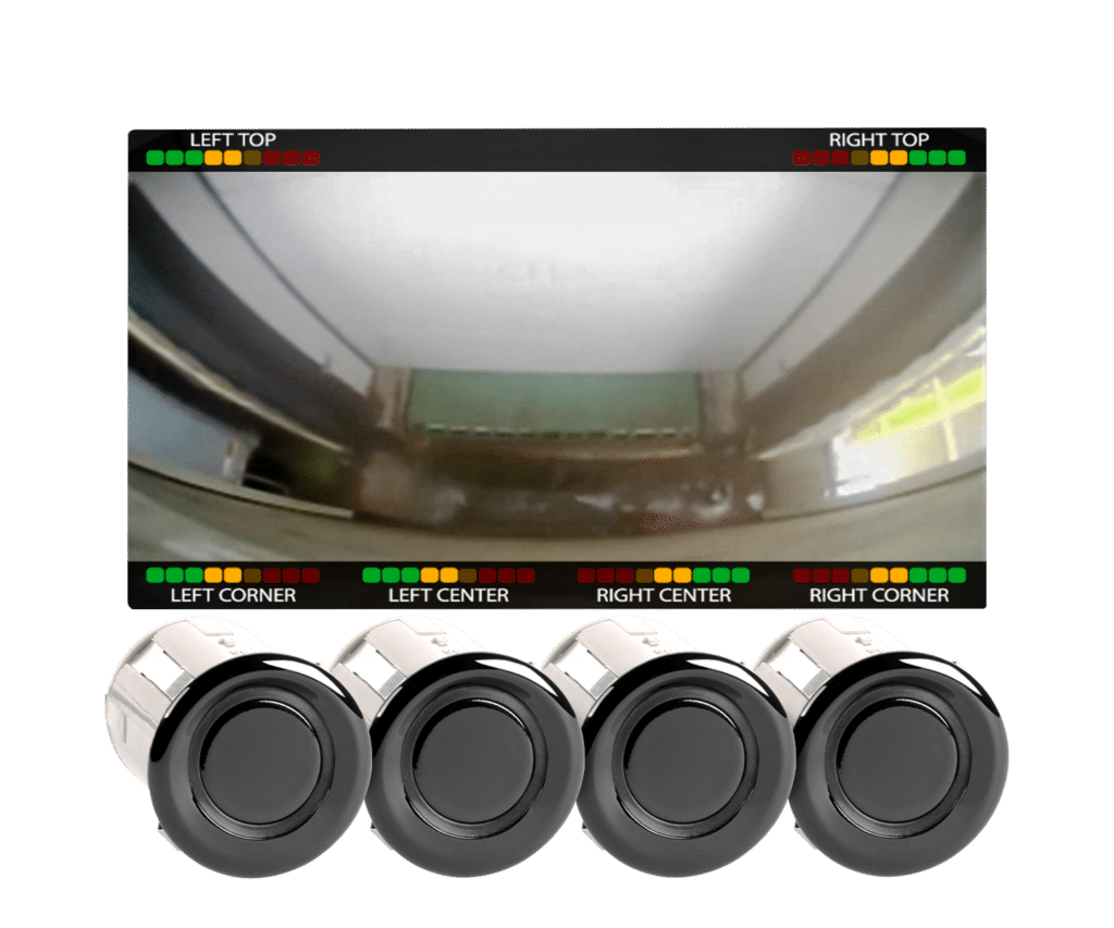
- Proximity detection/warning system with four bumper/body mount sensors
- Seamlessly integrates into any Voyager rear camera system
- Easy-to-read, on-screen display overlays that do not obstruct camera view
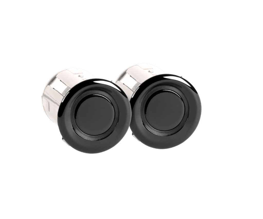
CVPS192SNSR
- Two-sensor add-on kit for CVPS192 system
- Proximity detection/warning system with four bumper/body-mount sensors
- Four detection zones with progressive beep tone
- Audio speaker/buzzer with High/Low/Off volume settings
- Blind spot detection system
- Two side-body mount sensors
- Radar based sensors

© Copyright Voyager. All Rights Reserved. | Privacy Policy
- Audio fed through monitor speaker
- Engineered for commercial vehicle environments
- Compatible with JENSEN® touchscreen stereo (with camera input)
- Compatible cameras: VCAHD140i, VCMS20, VCMS20B, VCMS17, VCMS17B
- Plastic bumper installation
- Built-in sensor isolators for metal bumper application
- Sensor sensitivity adjustment with rear step avoidance option
- No calibration, no on-screen display
- Radar based waterproof sensors
- Provides warning lights while sensor detects vehicle in blind zone with audible beep warning while turn signal is activated
- 1T2R antenna technology detects the vehicle in blind zone from both directions (vehicle approaching or passing the target vehicle)
- Self diagnostic mode
- Rear Cross Traffic Alert (RCTA) System – the sensors monitor the target object in the monitored area. System will give out a beep alert for potential risk while vehicle is in reverse mode
Wired Systems
Wireless systems, accessories.
Wireless camera system includes one WVOM541AP monitor, one WVCMS130AP rear camera, one suction cup monitor mount, and 12 volt DC accessory plug.
Monitor Features
- Supports up to 4 wireless cameras
- Auto-Pairing button instantly pairs (up to) 4 wireless cameras
- WiSight digital signal transmits through and around objects up to 60 feet away
- 5.6-inch color TFT LCD panel display with LED backlight
- Built-in speaker
- Suction cup mount and 12 volt DC plug included
- 12 volt DC power
- NTSC video signal compatible
- 960 W x 234 H screen resolution
- 100° H and 80° V viewing angles
- 500 nit brightness
- 250:1 contrast ratio
- 4:3 aspect ratio
Camera Features
- Rear wireless camera with WiSight technology
- High performance color optics
- 1/3-inch CMOS sensor
- Mirror image orientation
- 380 TV line resolution
- 0 Lux sensitivity
- 122° diagonal, 91° horizontal, 65° vertical viewing angles
- LEDs for low light assistance
The WVSXS70 single-camera system includes a 7-inch wireless LCD monitor, wireless rear camera, 12-volt accessory plug, suction cup monitor mount, non-corrosive camera mounting bracket, and stainless steel hardware.
WiSight® 2.0 technology digitally locks the camera to the monitor and blocks all outside signals. This eliminates interference and noise typical of analog wireless systems and delivers a sharp, vivid picture of the vehicle’s surroundings to the monitor.
Monitor (WVSXM70) Features
- Supports up to four (4) wireless cameras simultaneously
- Auto-Pairing capability allows the monitor to be paired with any of the wireless cameras with the touch of a button
- Strong signal transmits through and around objects up to 60 feet away
- Bright 7” display
- Supports normal and mirrored camera image
- Supports single, split, and quad view camera views
- Suction cup mount and 12V DC plug included
Camera (WVSXC150) Features
- 12VDC power
- High-performance color optics
- CMOS sensor technology
- IR LED Low-light assist
- Integrated microphone
- Wide viewing angle
- Non-corrosive camera mounting bracket
- Stainless steel hardware
The WVSXP43 single-camera system includes a 4.3-inch wireless LCD monitor, one wireless rear camera, a 12-volt power cord, and a suction cup mount.
Monitor (WVSXM43) Features
- Bright 4.3” display
- Displays graphic overlay that shows real-time distance from objects
- CMOS Sensor technology
- Displays graphic overlay that shows the real-time distance from objects
Camera (WVSXC160) Features
- Mobile digital video recorder
- 8-channel real time video monitoring and recording
- Compatible with any Voyager camera
- Compatible with AHD cameras
- Continuous recording as well as event recording (Sensor, speed, ignition off)
- GPS support for map syncing with Google (GPS antenna included)
- Multitasking function supports live camera monitoring, recording, play, and backing up footage
- 3 wire power system
- 2.5” 256GB SATA SSD Device for continuous recording
- 32GB SD Card for event recording (impact & alarm)
- SSD device lock key
- LED diagnostic indicators
- 3-axis G-sensor
- IR remote control
- Backup USB2 .0
- Multi-use camera
- Available in black (VCMS155B) or white (VCMS155)
- 1/4-inch CMOS sensor
- Electronic Automatic iris
- Selectable mirror or normal image orientation
- 420 TV line resolution
- 140° diagonal, 112° horizontal, 80° vertical angle of view
- 10 LEDs for low light assistance
- Aluminum housing
- Corrosion resistant
- Forward facing camera
- Electronic automatic iris
- 320 TV line resolution
- 1.0 Lux sensitivity
- 131° diagonal, 108° horizontal, 78° vertical angle of view
- Plastic molded housing
VCAHD140ICV
- Surface mount multi-use camera
- Analog high definition
- 1200 TV line resolution
- 146° diagonal, 129° horizontal, 86° vertical angle of view
- IR low light assistance
- Impact-resistant aluminum housing
- Surface mount light bar with camera
- Single pass wire entry installation
- Automotive exterior lighting-grade polycarbonate
- FMVSS108 compliant
- Available in black (VCMS202B) or white (VCMS202)
- 600 TV line resolution
- 145° diagonal, 109° horizontal, 93° vertical angle of view
- 19 LEDs for low light assistance
- Side body camera
- Available in left and right orientations in chrome (VCMS12LCM, VCMS12RCM), gray primer (VCMS12LGP, VCMS12RGP), and white (VCMS12LWT, VCMS12RWT)
- Zinc alloy housing and injected plastic body
- Available in left and right orientations in chrome (VCMS50LCM, VCMS50RCM), gray primer (VCMS50LGP, VCMS50RGP), and white (VCMS50LWT, VCMS50RWT)
- Available in variable orientation in black (VCMS50TBLK)
- Normal image orientation
- .5 Lux sensitivity
- 78° diagonal, 65° horizontal, 49° vertical angle of view
- Aluminum housing and injected plastic body
- Rear mount camera
- Mirrored image orientation
- 125° diagonal, 85° horizontal, 67° vertical angle of view
- 12 LEDs for IR low light assistance
- Supports 3 cameras with manual or triggered source selection
- Rearview mirror replacement monitor
- 7-inch wide format color TFT LCD display
- On-Screen Display (OSD) for AV source, picture adjustment, and volume control
- Manual and auto-dimming feature with screen saver mode
- Mechanical buttons with white backlit illumination
- Non-volatile memory
- NTSC and PAL video signal compatible
- 800 W x 450 H screen resolution
- 70° top, 50° bottom, 70° left, 70° right viewing angles
- 400 nit brightness
- 500:1 contrast ratio
- Analog 16:9 aspect ratio
- Supports 4 cameras with 6 triggers including Single image, Split-screen, and QuadView display modes
- 7-inch digital wide format color TFT LCD display
- DC auto source for switching triggers (turn signal compatible)
- Manual day/night display brightness controls
- Backlit control buttons
- Heady duty waterproof construction
- Rated and tested to withstand 4G continuous vibration
- AMPS mounting provisions
- Removable sun visor included
- 60° top, 70° bottom, 75° left, 75° right viewing angles
- 16:9 aspect ratio
- Supports three wired cameras with manual (push button) or automatic (trigger) source selection
- 7-inch wide format color LCD panel display with white LED backlight
- Day/night brightness modes
- Rubber keypad with white backlit illumination
- Auto-power on (stand by)
- Multiple mounting options (AMPS) compatible
- 480 W x 234 H screen resolution
- 55° top, 65° bottom, 70° left, 70° right viewing angles
- 450 nit brightness
- 400:1 contrast ratio
- 4.3-inch color TFT LCD panel display with LED backlight
- Anti-glare and anti-scratch protective lens
- Display graphic overlays show distance from objects in real-time
- Heavy duty waterproof metal housing
- Menu-selectable auto power on/off
- AMP mounting pattern
- 480 W x 272 H screen resolution
- 70° top, 70° bottom, 60° left, 60° right viewing angles
The WVSXP70 single-camera system includes a 7-inch wireless LCD monitor, wireless rear camera, 12-volt accessory plug, and suction cup monitor mount.
System includes WiSight receiver (WVRX1AP) and wireless camera (WVCMS130AP).
Receiver Features
- Universal installation with AMPS mounting provisions
- Compatible with any Voyager wired monitor for instant WiSight signal capability
- Adjustable antenna
- LED power indicator
- Auto-calibrate the images from four cameras to create a 360- degree image
- Walk-in Van 354” L x 118” W
- Bus 551” L x 118” W
- Heavy Duty Vehicles 236” L x 354” W
- Semi Trailer 630” L x 118” W
- Left/Right/Rear trigger function to switch between viewing angles
- Update software and vehicle image via USB
- 1/3-inch high performance color optic cameras
- Waterproof housing
- Plastic camera housing with stainless steel mounting bracket and aluminum
- Powder coated camera cover
VOS74MMCL3B
Wired camera system includes one VOM74MM mirror monitor, one VCMS140IB rear camera, one VCMS50RGP right side camera, one VCMS50LGP left side camera, and proprietary cabling.
Rear Camera Features
- 400 TV line resolution
- 150° diagonal, 120° horizontal, 90° vertical angle of view
Side Camera Features
Vos74mmcl2b.
Wired camera system includes one VOM74MM mirror monitor, one VCMS140IB rear camera, one VCMS50RGP right side camera, and proprietary cabling.
VOS74MMCL1B
Wired camera system includes one VOM74MM mirror monitor, one VCMS140IB rear camera, and proprietary cabling.
VOS719WPLD3B
Wired camera system includes one VOM719WP monitor, one VCMS17B rear camera, one VCMS50RGP right side camera, one VCMS50LGP left side camera, one VOSHD4MNT monitor mount, and proprietary cabling.
VOS719WPLD2B
Wired camera system includes one VOM719WP monitor, one VCMS17B rear camera, one VCMS50RGP right side camera, one VOSHD4MNT monitor mount, and proprietary cabling.
VOS719WPLD1B
Wired camera system includes one VOM719WP monitor, one VCMS17B rear camera, one VOSHD4MNT monitor mount, and proprietary cabling.
Pontiac G5 P0108: MAP Barometric Sensor → High Input
P0108 is a generic OBD-II trouble code. It indicates your Pontiac G5’s MAP (manifold absolute pressure) sensor’s voltage reading is outside of the normal operating range. The voltage is too high. It’s most commonly caused by a bad MAP sensor, wiring issue, or vacuum leak.
The MAP sensor measures the air pressure coming into your G5’s engine and sends that signal to the ECM. It does this by sending a voltage ranging from 1 to 5 volts. 1 volt would be idle speed. The signal should be at 5 volts whenever the vehicle is at wide open throttle. P0108 is triggered whenever the signal from this wire is MORE THAN 5 volts, which shouldn’t happen.
P0108 can also trigger if the ECM thinks the voltage coming from the MAP sensor is higher than it should be at any given time.

P0108 Quick Facts
- P0108 is caused when there’s too much voltage coming from the MAP sensor to the ECM.
- Most commonly caused by a bad MAP sensor. Vacuum or wiring issue are the next most common causes.
- Usually results in a rough running vehicle.
- A voltage meter is required to diagnose the MAP sensor.
P0108 Symptoms: Pontiac G5
P0108 is always going to do more than just trigger the check engine light . The MAP sensor is vital to a well running vehicle. If it’s gone bad, it’ll really affect drivability.
Here are the most common symptoms of P0108:
- Poor Gas Mileage
- Rough Running/Stalling Engine
- Motor Won’t Start at All
- Black Exhaust Smoke
- Check Engine Light

Pontiac G5 P0108 Causes + Diagnosis
When diagnosing this code, if your G5 is running fine you should first reset the code and take the vehicle out and try to reproduce the problem. It may have just been a one time thing.
The first thing that you should do is test the MAP sensor itself. A good voltmeter is necessary for this step. You can get them pretty cheap from any hardware store or Amazon. The reading from the voltmeter should be around 1 to 1.5 volts at idle. If it’s higher, you may need a new MAP sensor .
Here’s a pretty good YouTube video that shows exactly how you would go about testing the sensor:
Vacuum Leak
A vacuum leak is a very common reason that P0108 is triggered. If there isn’t enough vacuum going to the MAP sensor it’ll give a higher voltage reading than the operating conditions suggest should be there.
The vacuum supply to the MAP sensor could have a leak, or there could be a vacuum leak around the engine as a whole. Check all the vacuum lines on the engine. Check to see if any of them appear to be brittle, melted or cracked. If they are, replace them and see if that solves the problem.
Another place that vacuum can leak from the intake manifold. Here’s a solid article from Popular Mechanics on how to track down a vacuum leak .
Wiring Issues
The easiest thing that you can do when P0108 is triggered is check your G5’s wiring harness. Is it plugged in to the MAP Sensor tightly? Does it have any visible signs of damage? Follow it as far as you can and make sure. It’s going to have a ground wire. Make sure that ground is plugged in tightly. Here’s a good video on how to find a short in a vehicle.
While the three causes listed above are the most common reasons P0108 shows up, there are other reasons as well. If your G5’s motor is worn out and isn’t producing a good vacuum anymore, that’ll cause the MAP sensor to output a higher voltage at all times and throw the code.
It’s also possible that an engine that is misfiring or has low fuel pressure can trigger this code as well. It would need to be a pretty noticeable misfire. You should also get P0300 or P030X (X representing the cylinder number of the misfire) with P0108 if misfiring was the case.
Conclusion: P0108 G5
While it is most likely to be the MAP sensor itself that is causing P0108 in your Pontiac G5, properly identifying the problem can save you from purchasing and installing a sensor that you don’t need If there is anything that you would like to add, please leave a comment below. Good luck!
IMAGES
VIDEO
COMMENTS
Olá amigos mais um vídeo sobre como fazer um teste simples de alimentação do sensor MAP do Voyage g5 e derivados.
Olá amigos mais um vídeo de manutenção desta vez sobre sensor MAP com leitura alta, O que acontece quando o sensor MAP está com defeito?, essa pergunta estar...
Olá amigos mais um vídeo sobre dica de manutenção do sensor MAP.
Unraveling the Mysteries of Engine Management Systems with Map Sensors 101. In the vast realm of automotive technology, understanding the intricacies of engine management systems is crucial for any enthusiast or aspiring mechanic. In this comprehensive guide, we delve into the heart of these systems, focusing on the pivotal role of map sensors.
What is the MAP sensor of your G5? In short: The MAP sensor is the sensor that measures the pressure of the intake manifold, also called inlet manifold, of the engine (the part where the air comes in). If it gets damaged, you should replace it, because it cannot be fixed. The acronym MAP stands for Manifold Absolute Pressure. The MAP sensor is next to the butterfly valve, and it is usually ...
Descrição **DESCRIÇÃO DO PRODUTO Sensor Map Vw 0261230235 03C906051F Bosch Original **APLICAÇÃO Fox 2003 até 2014 SpaceFox 2006 até 2014 CrossFox 2006 até 2014 Gol G3/G4/G5/G6 2003 até 2016 Voyage G5/G6 2009 até 2016 Saveiro G5/G6 2009 até 2016 Golf 2002 até 2013 Jetta 2.5 2005 a 2010 Jetta 2011 Jetta Variant 2008 Em Diante Passat Variant 2009 À 2011 Polo 2003 À 2014 Touareg ...
On my model the MAP sensors must be in the ECU itself. You are right. I put together that guide, but I should try and edit it. The guide is actually for a 4 pin sensor (temperature and pressure), even though the location picture shows a 2 pin intercooler. The 2 pin MAP sensor is just a temperature sensor as you say.
Sensor Map Bosch 0261230235 Vw Voyage G5/g6 2016. R$ 199 99. em. 6x. R$ 33 33. sem juros. Frete grátis.
Sensor Map Gol Voyage Saveiro G5 G6 Original Vw 03c906051f. por Volkswagen. R$ 324, 45. em. 12x . R$ 31, 46. Frete grátis. Sensor Map Original Gol Fox Voyage Up Jetta Golf. por Volkswagen. R$ 363, 86. em. 12x . R$ 35, 28. Frete grátis. Sensor Pressao Coletor Map - Voyage 2011 2012 2013. R$ 235, 74. em. 7x . R$ 33, 68.
Frete grátis no dia Compre Sensor Map Voyage parcelado sem juros! Saiba mais sobre nossas incríveis ofertas e promoções em milhões de produtos. ... Sensor Map Bosch 0261230235 Vw Voyage G5/g6 2009 Até 2016. R$ 199, 99. em. 6x . R$ 33, 33. sem juros. Frete grátis. Sensor Map Amarok Fox Gol Jeta Polo Saveiro Up Virtus Voyage. R$ 129, 99 ...
Olá amigos mais um vídeo sobre sensor map Voyage g5 em curto circuito e como fazer para identificar se existe curto circuito neste sensor do carro.
VTT BMW 5-Bar Map Sensor S58, B58, B48, B47, B42, B57, B46 - Vargasturbo Turbo Technologies. Looking to go above 45 psi in your BMW-powered vehicle? Looking for a plug-and-play solution? We have you covered with our BMW 5 bar sensor. These will allow 58 psi to be read and are factory plug, and play.
Sensor Systems The world is full of obstacles and we want you to see them coming. Our sensor systems are designed to detect objects around you and deliver audible or visual warnings. CVPS192 Proximity detection/warning system with four bumper/body mount sensors Seamlessly integrates into any Voyager rear camera system Easy-to-read, on-screen display overlays that do […]
December 17, 2019 by Jason. P0108 is a generic OBD-II trouble code. It indicates your Pontiac G5's MAP (manifold absolute pressure) sensor's voltage reading is outside of the normal operating range. The voltage is too high. It's most commonly caused by a bad MAP sensor, wiring issue, or vacuum leak. The MAP sensor measures the air ...
Equip cars, trucks & SUVs with 2007 Pontiac G5 MAP Sensor from AutoZone. Get Yours Today! We have the best products at the right price. skip to main content. 20% off orders over $125* + Free Ground Shipping** Eligible Ship-To-Home Items Only. Use Code: AUTUMNDEAL. Menu ...
Carquest Premium - Inline Connector (Part No. PTA1274) Description. from $31.49. View Product. Compare 2007 Pontiac G5 Suspension Self-Leveling Sensor Connector brands. Check prices & reviews on aftermarket & stock parts for your 2007 G5 Suspension Self-Leveling Sensor Connector. Order your parts online or pick them up in-store at your local ...
Olá amigos mais um vídeo sobre sensor Map com leitura alta o que pode ocasionar isso, sem que o sensor esteja com defeito.
Elektrostal is a city in Moscow Oblast, Russia, located 58 kilometers east of Moscow. Elektrostal has about 158,000 residents. Mapcarta, the open map.
Explore Russia local news alerts & today's headlines geolocated on live map on website or application. Focus on politics, military news and security alerts. Security services searching Wildberries warehouse in Elektrostal looking for illegal migrants, and the men avoiding conscription Elektrostal, Moscow - Map of Latest News and incidents from ...
Olá amigos mais um vídeo sobre quando limpar sensor map vamos ver quando fazer um limpeza de manutenção dessa peça no motor do carro!!
wagon map eng 150110-out. Title. wagon_map_eng_150110-out. Created Date. 1/11/2015 9:54:38 PM.
Ukrainian military had 59 combat engagements with Russian forces near Synkivka of Kharkiv region, south to Terny of Donetsk region, Klischiyivka and Andriyivka of Donetsk region, Avdiyivka, Syeverne, Tonenke, near Pervomayske and Nevelske of Donetsk region, near Novomykhaylivka of Donetsk region, south to Chervone, west to Verbove and north to Novoprokopivka of Zaporizhzhia region, - General ...
Olá amigos mais um vídeo sobre sensor map sujo de óleo o que fazer? para limpar.