
- 800.497.6255

Hours of Operation
- Sign In Create
- Relectric Account Benefits
- Expedite your online checkout
- Store billing and shipping info
- Track your orders
Circuit Breaker Under Voltage Release – How Does It Work?
Under voltage release.
An under voltage release is an optional device installed in a circuit breaker that automatically triggers a power trip when the power falls below a preset level, usually between 70 and 35 percent of the UV rating. The circuit breaker does not power it. Instead, it receives its power from an alternative source, such as a battery. It was initially designed for use in coal mines but can now be found in any field employing heavy industry.
How it works
An under voltage release device consists of a solenoid magnet with a moving armature fixed to a spring-loaded latch. This latch restrains a spring-biased plunger, which when released, makes contact with the breaker trip bar to trip the breaker.
As long as the voltage connected to the solenoid magnet remains normal, the magnetic force is strong enough to overcome the spring force and keep the trip bar from releasing. But once the voltage cuts off or falls too far below the preset level, the spring force overcomes the magnetic force. This force unlatches the plunger, which then trips the power.
When the circuit breaker contacts are open, a mechanical reset leaver, powered by a central contact arm, holds the solenoid magnet in a sealed-in position. Once power is restored, the magnet reenergizes and holds the plunger in its position allowing the circuit breaker to be reset and turned back on. If the power has not been restored to the solenoid coil and someone tries to reset the breaker, it will only trip again.
It can be mounted on either the left or right pole and installed next to the operating system of a circuit breaker case. Although attached to the trip unit, the spring-loaded release extends through a knockout in the trip unit case. When installed, it won’t interfere with the standard tripping action of a circuit breaker when it experiences a power surge.
The under-voltage release is available for both AC and DC usage with several different voltage ratings to choose. Connections for a UVR come in four different forms. The standard is pigtail leads (18 inches long minimum), exiting the rear of the base directly behind the UVR. These leads are color coded for identification.
Other configurations available include a terminal block mounted on the same side of the base as the accessory. Another has leads exiting the same side of the base as the accessory. The fourth version has leads coming out on the opposite side of the accessory.
Difference between Shunt Trips
A similar appliance that can be combined with a UVR in a circuit breaker is called a Shunt Trip . It has a similar design and function to a UVR, but is instead activated when there is a power outage. Remote control can enable it, but the solenoid coil only carries a temporary charge and is not rated for continuous use.
Eaton’s Under-Voltage Releases
Although UVR’s are not required by law in most cases, they are still recommended. When sensitive equipment is in use, an under-voltage, such as in brownouts, can cause data loss or fry the entire system. The other danger is one of safety; some industrial equipment can be a safety concern if the power dips below its required level.
Eaton’s under-voltage releases are designed to provide the protection needed for electrical systems with a compact design that is easy to install. They have both terminal magnetic and electronic magnetic units available, as well as a host of other accessories.
Eaton has been working in the industry for many years and continues to produce reliable electrical appliances for both commercial and residential use. Their high level of quality control and commitment to safety make Eaton one of the best brands in electronic devices.
Eaton – UVH4RP03K
The G series is designed for all circuit protection needs around the world. These are factory sealed and must be installed onsite. This high-performance UVR can be used for both regional and industry requirements.
Its compact design allows it to be installed easily while still leaving plenty of panel space. It has a left pole mount and a voltage rating from 525 to 600 VAC. Along with built-in ground fault protection, this makes it one of the best UVR’s for EG and JG circuit breakers.
Eaton – 1228C76G03
This classic UVR is made for standard MARK 75 mining service use, with a 120V LAMH electrical reset under-voltage release. This UVR is popular for its reliability and ease of use in factory settings, making it a prime choice in the mining industry.
Series C Eaton-Cutler Hammer 1373D62G09
This 50Hz under-voltage release has a 240V release mechanism and is designed for use with GD breaker parts and accessories.
Eaton Circuit Breaker under voltage release mechanisms are popular due to their high quality and reliability, whether for commercial or residential use. They’re easy to install and have a high safety record across all appliances.
- Get custom product tools and services
- Access training
- Manage support cases
- Create and manage your orders (authorized partners only)
Schneider Electric USA Website
Search FAQs
How does an undervoltage accessory trip a circuit breaker.
Article available in these languages: Spanish
Released for: Schneider Electric USA
Articles that might be helpful
Discuss this topic with experts
Start here!
Find answers now. Search for a solution on your own, or connect with one of our experts.
Contact Support
Reach out to our customer care team to receive more information, technical support, assistance with complaints and more.
Where to buy?
Easily find the nearest Schneider Electric distributor in your location.
Search topic-related frequently asked questions to find answers you need.
Contact Sales
Start your sales inquiry online and an expert will connect with you.
Under Voltage Relay Working principle, Connection diagram and Parameters
- LT Protection Relay
- Under Voltage relay
- Under voltage relay.
- Why it is used?
- Connection diagram of under voltage relay.
- Working principle.
- Relay setting parameters.
1 - Under voltage relay:
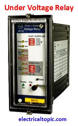
Under voltage relay is an electrical protection device which is used for prevention of decreasing system voltage and operated after crossing pre set value of voltage and time then a tripping signal is provided to the circuit breaker tripping coil. It is used in transformer outgoing isolation panel or LT panel or feeder panel for controlling over voltage. Under voltage relay continue monitors the default voltage level of system. If the voltage level is exceed pre set voltage limit then system will be tripped.
2 - Why it is used?
Under voltage condition is very dangerous in system voltage. Due to under voltage the system will start to take more current as per ratings so resultant due to flowing more current then insulation which is used on wire, cable, windings, may be failure, burn or heat. It means under voltage is very dangerous for equipment health. So under voltage relay is used. For exp: Default system voltage is 415V and -5% voltage variation is tolerated. If above 5% voltage can be dangerous for system. So it is the important reason for using under voltage relay.
3 - Connection diagram of Under voltage relay.
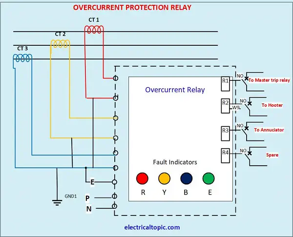
4 - Working principle of Under voltage relay.
Under voltage preset value of - 5% multiply of system voltage and time 0.1 to 1.6 second can be adjusted as per requirement. If the voltage is decreased pre set value and time limit then under voltage relay, a tripping signal is provided to the circuit breaker to tripping coil resultant tripping coil pushes to the trip mechanical latch. After tripping condition, the Over voltage relay provides us alarm, red indication on display screen and reset push button comes out side. Again for normal operation of UVR, we will have to press the reset push button so that system could be work normally. It is microprocessor based relay and it is so important for prevention of under voltage.
5 - Relay setting parameters:
Go back to index ↑, related topic.
- What is the over voltage relay and connection diagram ?
- What is the earth fault relay, working principle and connection diagram?
- What is the differential relay, working principle and connection diagram?
- What is the RPR- reverse power relay, working principle and connection diagram?
- What is the circuit breaker, working principle and connection diagram?
- What is the electrical panel , components and connection diagram?
Electrical and Mechanical Job Interview Training. Get boost in your job or get new opportunity

Electrical E-book
(Get important knowledge about industrial electrical, building maintenance in E-book )
HT system, LT system, Transformer, Electrical panel, Motor and Starter, Circuit breakers, Protection relays, Measuring meters.

Technical Interview
( Electrical system, Diesel generator, BMS, AC, Chiller plant, UPS, WTP, STP, ETP, Fire and safety.)
electrician, maintenance supervisor, AC operator, chiller plant operator, DG operator, BMS operator, Shift engineer, Maintenance engineer, technical executive, sr. engineer, assistant facility manager,
Learn Fast and Improve Your Skill in Electrical Field Basic and practical theory, repair and maintenance, protection and testing.
For any query :- write to us as below mentioned email .. for official :- [email protected] for technical information :- [email protected] for interview preparation :- [email protected].
Nader Circuit Breaker

- Solutions Back
- Download Back
- About Us Back
Principle diagram of circuit breaker undervoltage release
In the event of a power failure, the air switch will trip by itself, generally because the air switch has an undervoltage trip protection device. When the power fails, the undervoltage release will trip.
The working principle of undervoltage release (see the figure below):
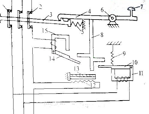
1. When the line voltage is normal, the voltage release 11 generates enough suction force to overcome the action of the tension spring 9 to pull in the armature 10, and the armature and lever are separated, the lock and the hook can be locked, and the main contact can be closed. .
2. When the voltage on the line disappears or the voltage drops to a certain value, the suction force of the undervoltage release disappears or decreases, the armature is pulled apart by the tension spring 9 and hits the lever, and the main circuit power supply is disconnected.
3. For the same reason, when there is no power supply voltage or the voltage is too low, the automatic air switch cannot turn on the power supply.
Can DC circuit breaker and AC circuit breaker be used in common?
Precautions for short-circuit short-delay selective protection
The difference between 1P, 2P, 1P+N circuit breakers
Selection principle and setting principle of low voltage circuit breaker
Air Circuit Breakers [AKH, AKS, AKN Series] : Accessories : Under Voltage Trip device [UVT]
- If the voltage of the main or the control power is under voltage, UVT which is installed inside of the breaker breaks the circuit automatically. Please connect with UVT time-delay device in order to present the timedelay function because UVT is technically instantaneous type.
- The closing of a circuit breaker is impossible mechanically or electrically if control power not supplied to UVT. To close the circuit breaker, 65–85% of rated voltage should be applied to both terminals of UVT coil (D1, D2).
- When using UVT coil, the double trip coil can not be used, and the location of trip coil is changed.
1. Rated voltage and characteristics of UVT coil
- Note) Operating voltage range is the min. rated voltage standard for each rated voltage (Vn).
2. Specification of the wire
- Refer to the below table regarding the length and specification of wire when using trip coil with DC 24–30 [V] or DC/AC 48–60 [V] of rated voltage.
The maximum wire length
- Note) In case of using UVT coil, the location of TC coil is changed.

Undervoltage Protection (ANSI 27)
Presentation
Undervoltage protection (ANSI 27) constantly monitors the system voltage. If the voltage level of an installation goes out of its acceptable limits, the information provided by undervoltage protection can be used to initiate appropriate action to restore good operating conditions in the installation.
The information provided by undervoltage protection is used to generate alarms and circuit breaker tripping when required. In addition, the constant monitoring of phase-to-phase or phase-to-neutral voltages enables appropriate action to be initiated to safeguard the operation of the installation during abnormal or critical situations, for example, load shedding, source change-over, and emergency generator starting.
Prerequisites
Undervoltage protection is available when the ANSI 27/59 - Under/Over voltage protection Digital Module is purchased and installed on a MicroLogic X control unit .
Undervoltage protection requires an external 24 Vdc power supply.
Undervoltage protection is compatible with:
o MicroLogic 2.0 X, 5.0 X, 6.0 X, and 7.0 X control units for IEC standard
o MicroLogic 3.0 X, 5.0 X, and 6.0 X control units for UL standard
o MicroLogic X control units with firmware version greater than or equal to 002.000.002. Earlier firmware versions need to be updated .
Data from the Digital Module is available remotely through IFE/EIFE or IFM communication interfaces, if the IFE/EIFE or IFM firmware version is compatible with the Digital Module. For more information, refer to firmware compatibility of the communication interfaces .
Operating Principle
Inhibiting Protection
To inhibit the undervoltage protection (ANSI 27-1 or ANSI 27-2), both the following conditions must be met:
o Inhibition is enabled on a specific protection (ANSI 27-1 or ANSI 27-2) by setting the Inhibition parameter to ON.
o Inhibition of optional protections is activated by an input of the IO module. The function Inhibit optional protection must be assigned to an input of the IO module.
For more information about inhibiting optional protections, refer to Enerlin'X IO - Input/Output Application Module for One Circuit Breaker - User Guide .
NOTE: The undervoltage protections (ANSI 27-1 or ANSI 27-2) can be inhibited separately, or together.
Voltage Measurement
For undervoltage protection set in tripping mode, the voltage must be measured on the power source side to allow closing of the circuit breaker. As standard, the MicroLogic X voltage input is directly connected to the internal pickup voltage (PTI) on the bottom side of the circuit breaker. So:
o If the circuit breaker is bottom fed, the internal pickup voltage (PTI) is suitable for undervoltage protection and circuit breaker closing.
o If the circuit breaker is top fed, an external voltage input is required. The external voltage tap (PTE) option must be used to measure the voltage on the power source side or use the Force to Off when CB is open option.
Setting for All Under/Overvoltage Protections
Select the type of voltages to monitor before making other settings:
o VLL phase-to-phase voltage selection (factory setting)
o VLN phase-to-neutral voltage selection (this setting should be selected only with 4-pole circuit breakers or 3-pole circuit breakers with ENVT wired and configured)
It can be set as follows:
o With EcoStruxure Power Commission software (password-protected)
o With EcoStruxure Power Device app (password-protected)
Setting ANSI 27-1 and ANSI 27-2 Undervoltage Behavior Parameter
For a top fed circuit breaker without the PTE option, if the undervoltage protection trips the circuit breaker, it can be difficult to close the circuit breaker again. This is due to the protection detecting the absence of voltage and tripping immediately. To enable closing of the circuit breaker, the undervoltage behavior parameter can be set to Force to Off when CB is open .
The undervoltage behavior parameter, Vmin behavior, has two settings:
o Normal : the protection functions as normal
o Force to Off when CB is open : undervoltage protection is disabled when the threshold is reached and the circuit breaker is in the open position
Setting ANSI 27-1 Protection
The settings for undervoltage protection on one phase (ANSI 27-1) are:
o Vmin1 mode: enables (ON) or disables (OFF) undervoltage protection on one phase
o Vmin1 action: sets the result of undervoltage protection activation as trip or alarm
o Trip: the circuit breaker trips and three events are generated (start, operate, and trip)
o Alarm: two events are generated (start and operate)
o Vmin1 inhib: enables (ON) the protection to be inhibited by IO module
o Vmin1: threshold of undervoltage protection on one phase
o tVmin1: time delay of undervoltage protection on one phase
They can be set as follows:
The dual settings function does not apply to undervoltage protection on one phase. When the dual settings function is enabled, undervoltage protection settings are the same whether set A or set B settings are activated.
Setting ANSI 27-2 Protection
The settings for undervoltage protection on all phases (ANSI 27-2) are:
o Vmin2 mode: enables (ON) or disables (OFF) undervoltage protection on all phases
o Vmin2 action: sets the result of undervoltage protection activation as trip or alarm
o Vmin2 inhib: enables (ON) the protection to be inhibited by IO module
o Vmin2: threshold of undervoltage protection on all phases
o tVmin2: time delay of undervoltage protection on all phases
The dual settings function does not apply to undervoltage protection on all phases. When the dual settings function is enabled, undervoltage protection settings are the same whether set A or set B settings are activated.
Protection Settings
The following are the settings for ANSI 27-1 and ANSI 27-2:
Protection Characteristics
Characteristics of undervoltage protection:
o Definite time delay
o Instantaneous reset time
o Hysteresis: fixed 98%
o Minimum breaking time 50 ms
o Maximum breaking time 140 ms with time delay set to 0 s
Predefined Events
The function generates the following predefined events:
Predefined events cannot be modified by the user. For general information about events, refer to Event management .
Protection events are generated as follows:
o The start event is generated when the protection picks up.
o The operate event is generated when the protection time delay elapses.
The operate event is not generated when the optional protection is inhibited.
o The trip event is generated when the circuit breaker tripping voltage release (MITOP) activates.
The trip event is not generated when:
o The optional protection is set in alarm mode
o The optional protection is inhibited
Recommended Actions
Resetting a Trip Event
For information about resetting the circuit breaker after a trip due to an electrical fault, refer to the relevant document :
o MasterPact MTZ1 - Circuit Breakers and Switch-Disconnectors - User Guide
o MasterPact MTZ2/MTZ3 - Circuit Breakers and Switch-Disconnectors - User Guide
DOCA0102EN-06
© 2020 Schneider Electric. All rights reserved.
- Practical Electrical
- Transformer
- Transmission
- Induction motor
- Electronics
- Generator Protection

- Electrical Basic
Under Voltage Protection Working Principle 27
Under voltage protection working principle 27:.
Under voltage fault protection is used to protect the alternator/generator/transformer winding from low voltage operation. Under voltage protection sense the phase to phase voltage of the generator/transformer using instrument transformer (Potential transformer). When the voltage drops below the rated voltage typically 85% (stage 2)-90% (stage 1) the under voltage protection will be activated.
Principle of Under voltage protection:
Three number of potential transformer normally installed in the generator LAVT panel (lighting arrester voltage transformer). They detect the voltage across the generator in real time. When the voltage across the generator winding drops the simultaneous voltage drop occurs in the PT output also. The reduced or dropped voltage activate the power system alarm or trip circuit.
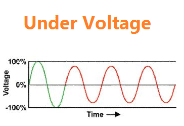
Reason Under voltage protection:
i.e The output from the generator’s LAVT potential transformer will be given to the under voltage coil typically 110 Volts relay coil. In principle of U/V coil, which do not trip the circuit breaker when the voltage across the PT is high. When the voltage drops the preset value, the voltage coil operates the circuit breaker.
The generator under voltage protection consists of two stage tripping. Stage 1 trip command is given to grid circuit breaker and stage 2 trip command is given to generator circuit breaker. Most of the time in synchronous generator, the under voltage fault occurs from the grid due to earth fault and line short circuit. That’s why, the first stage will be given to grid circuit breaker.
At that same time, the under voltage fault occurs due to failed excitation, diode failure, under frequency or turbine low speed, failed PT fuse etc. [wp_ad_camp_1]
Under voltage relay setting:
Stage1: 90% of the rated voltage trip command to grid circuit breaker.
Stage2: 85% of the rated voltage, trip command to Generator circuit breaker.
ANSI code for under voltage protection: 27
Relay acted:
- 27 relay opted
- 86M grid mater trip opted-stage1
- Annunciator under voltage alarm
Note: if the under voltage occurs due to excitation failure, then check your generator excitation system.
RELATED ARTICLES MORE FROM AUTHOR
Merz Price Differential Protection for Transformer Explanation
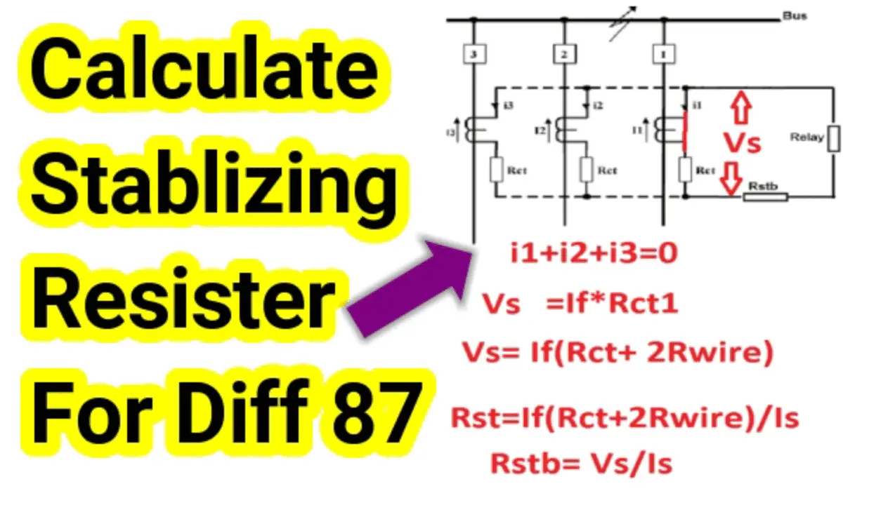

How to Calculate Stabilizing Resistor for High Impedance Differential Protection
No Volt Release (NVR) and No Voltage Relay Working Principle
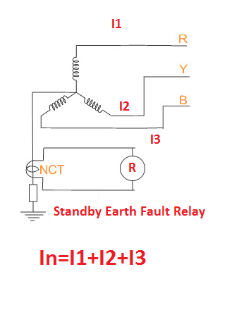
Standby Earth Fault Relay 51N, Operation, Construction
Maximum Demand Formula, Calculation & MD Calculator

LED Light Power Consumption Calculation & LED Energy Bill Calculator

What is Electric Arc?

kW kVA kVAR formula, Relation with Power Factor
Plug setting multiplier & time setting multiplier.
Different Types of Circuit Breakers Working, Uses, Voltage Level
What is Type 2 coordination & Type 1 Coordination

What is Voltage Regulation?
Leave a reply cancel reply.
Save my name, email, and website in this browser for the next time I comment.
- LS Industrial Systems Manuals
- Circuit breakers
- Susol Series
- Technical catalogue
LS Industrial Systems Susol Series Technical Catalogue
- page of 157 Go / 157
Table of Contents
- Troubleshooting
- Susol / Metasol Series Characteristics
- Metasol Series
- Standard and Approvals
- Main Body Structure - Auxiliary Devices
- Cradle Accessories / External Installation and Others
- OCR Characteristics by each Type
- Introduction of Digital Trip Relay
- Nameplate Features
- External View and Inscriptions
- Externals and Inscriptions
- Internal Configuration
- Fixed Type / Draw-Out Type
- Terminal Configuration
- Basic Function and Breaking Operation
- Circuit Closing
- Current Conducting
- Circuit Opening, Current Breaking
- Closing & SHT Coil
- External Configuration and Wiring Diagram
- Rated Voltage and Characteristics of Closing / Shunt Coil
- The Specification of Using Wire
- UVT Time Delay Controller
- Under Voltage Trip Device, UVT
- Rated Voltage and Characteristics of UVT
- Rated Output Contact
- Trip Alarm Switch, al
- Electrical Characteristics of al Switch
- Comparison Table Upon Types
- N, a / S Type Knob Configuration
- N, a Type Knob Information
- S Type Knob Configuration
- Key Configuration
- LED Information
- N Type KEY / LED / A, P, S Type KEY / LED
- Internal Circuit Diagram
- Long- Time Delay Relays
- Short-Time Delay Relays
- Instantaneous
- Ground Fault
- Long-Time, Short-Time and Instantaneous Protection
- Ground Fault Protection
- Optional Relays for P,S Type - OV, UV, Rpower
- OVR - over Voltage Relay
- Relay Selection Standard Table
- UVR - under Voltage Relay
- Lunbal - Current Unbalace Protection
- OF - over Frequency Protection
- Optional Relays for P,S Type - Vunbal, Lunbal, OFR, UFR
- Vunbal - Voltage Unbalace Protection
- Earth Leakage Relay with External CT
- External CT Type Wiring 1
- Optional Relay - External CT Earth Leakage
- Earth Leakage Relay
- Earth Leakage Relay Standard Table
- Optional Relay - Earth Leakage (EL)
- Measurement Accuracy for a (Current), P, S Type
- Voltage Dividing Module
- Voltage Input / Specification for P, S Type
- Phasor Value - Fundamental Frequency Element Size
- Voltage / Current RMS Value for P, S Type
- Definition of Unbalance Factor 1
- Voltage / Current Unbalance for P, S Type
- Active Power Calculation
- Power Calculation for P, S Type
- Reactive Power Calculation
- Apparent Power Calculation
- Electric Energy - Bidirectional Metering
- Indication of Power and Power Factor According to Phase
- Power Factor Calculation
- Demand / Peak Demand for P, S Type
- Demand Measurement, Peak Demand Record
- Frequency Measurement
- Harmonics Calculation
- K-Factor Definition
- TDD Definition
- THD Definition
- Io(Input-Output)Port
- IO Type and Configuration
- What Is ZSI?
- ZSI Configuration
- The Use of Remote Reset
- The Use of Solid Relay
- Rated Output
- Rs-485 Modbus Comm
- Profibus -DP COMM
- External View and Composition
- Switch Setting
- Product Input Rating
- Product Output Rating
- Communication Standard
- Profibus - DP Communication Introduction
- Communication Cable Standard
- Data Exchange
- Network Configuration
- Communication Frame
- Physical Layer
- Operation Circuit
- RTD Summary
- Temperature Sensor
- TRIO Unit Temperature Measuring Operation
- OCR Tester Characteristic
- Explanation on Function Key
- OCR Tester Check List
- Safety Precaution
- Outline for Safety Operation
- Qualified Person
- Danger, Warning, Caution
- Hazard of Bodidy Injury or Equipment Damage
- Installation of Fixed Type
- Installation of Draw-Out Type
- Installation of Insulation Barrier
- Service Condition
- Normal Service Conditions
- Special Service Conditions
- Insulation Clearance
- Minimum Insulation Clearance
- Manual Operation
- Manual Charging
- Manual Closing
- Manual Tripping
- Draw-In Operation Procedure
- Electrical Closing
- Electrical Trip
- Electrical Operation
- Draw-Out Operation
- Draw-Out Operation Procedure
- Low Voltage Circuit Breaker’ S Characteristic Curve
- Selectivity Techniques
- Fully Rated Protection
- Discrimination Protection
- Picture 2. Discrimination Coordination
- Complete Selectivity
- Current Selectivity
- Time Selectivity
- ZSI Operation Principle
- ZSI Applied in Power Supply
- ZSI (Zone Selective Interlocking)
- IDMTL (Inverse Definite Minimum Time Lag)
- Discrimination Table
- Main Breaker
- Main Body Mounting
- ON / off Button Lock
- Insulating Barrier between Poles / Phases
- Cradle Mounting
- Mechanical Interlock
- Door Interlock : DI
- MOC (Mechanical Operated Cell Switch, MOC)
- Safety Shutter Lock
- Mounting Direction of Shutter Lock
- Guide Shutter
- Cell Switch, C
- Miss Insertion Prevent Device (MIP)
- Externals and Operating Characteristics
- The List of Combination
- Lift Hooking
- ATS Controller with Acbs
- External Mounting
- In Case of 2 Acbs with ATS Controller
- In Case of 3 Acbs with ATS Controller
- Installation Method
- Shorting B-Contact
- Circuit Diagram
- Condenser Trip Device (CTD)
- Externals and Ratings
- Optional Accessories
- Key Lock : K1
- Key Interlock : K2
- Key Interlock Double
- In Case of Extended ACB Compartment
- Auxiliary Contact (AX)
- Standard Classification
- Contact Operation
- Charging Motor
- The Classification of Motor
- Safety Shutter
- Before Assembly
- After Assembly
- Ready-To-Close Contact
- Pad Lock / Position Lock
- Arc Cover (Component for Zero Arc Space)
- Control Terminal Block COVER
- Externals and Frame Sizes
- Fixing Block
- Racking Interlock
- Temperature Measuring Sensor
- MRB (Manual Reset Button)
- SLOW Closing Lever
- Automatic Spring Release (Energy Release)
- Transporting and Storage
- Lifting by Forklift
- Transporting Method of Fixed Type
- Storage Method
- Precaution of Storage
- Precaution of Transporting
- Check Points before Inspection
- Check Points Upon Receiving
- Caution for Installation Inspection
- Maintenance Cycle Upon Using Condition
- Inspection Method after Trip Operation of Circuit Breaker
- Inspection Method of Arc Chamber
- Separate Procedure of Arc Chamber
- Inspection Method for Moving Contact Condition
- Inspection Method for Cluster
- The Standard Figure for Contact Replacement
- Mounting and Separation of Cluster
- Defects and Troubleshooting Guideline
- Control Circuit
- External Dimension
- Draw-Out Type 2000AF (630A~1600A)
- Fixed Type 2000AF (2000A)
- Draw-Out Type 2000AF (2000A)
- Fixed Type 4000AF (630A~3200A)
- Draw-Out Type 4000AF (630A~3200A)
- Fixed Type 4000AF (4000A)
- Draw-Out Type 4000AF (4000A)
- Fixed Type 5000AF
- Draw-Out Type 5000AF
- Fixed Type 6300AF (4000~6300A)
- Draw-Out Type 6300AF(4000~6300A)
- Ordering Sheet
- Susol/Metasol ACB
Advertisement
Quick Links
- 1 Digital Trip Relay
- Download this manual
Related Manuals for LS Industrial Systems Susol Series

Summary of Contents for LS Industrial Systems Susol Series
- Page 1 Technical Catalog Meta Solution Super Solution...
- Page 2 Meta solution Super solution...
- Page 3 Contents Overview Structure and Operation Internal Electrical Accessory Digital Trip Relay Digital Trip Relay Accessory Installation and Service Condition Operation Protective Coordination Accessories Handling and Maintenance Control Circuit and Dimension Ordering Sheet Technical catalog for Susol & Metasol ACB...
- Page 4 Overview 1. Product Introduction 2. Accessories 3. Introduction of Digital Trip Relay 4. Ratings 5. Externals and Inscriptions...
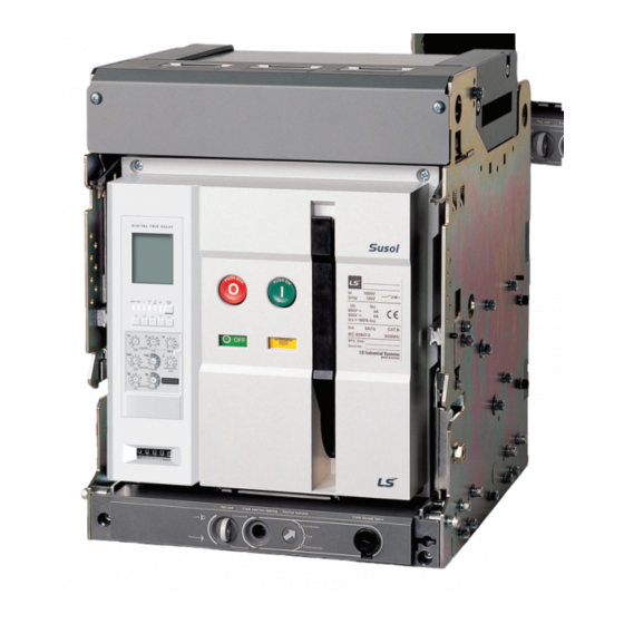
- Page 5 Susol Series Susol Series ACB has high breaking capacity and multi-function product at the world class level which is used with P and S type of digital trip relay. It is basically equipped with arc box to assure arc space zero performance.
- Page 6 Overview 1. Product Introduction Standard and Approvals It has obtained approvals in accordance with following international standard and can be applicable to service condition defined from international standard. � � IEC 60947-1 Low-voltage switchgear and controlgear - Part 1: General rules �...
- Page 7 Technical catalog for Susol & Metasol ACB 2. Accessories Main Body Structure - Auxiliary Devices � � � � � � � � � � � � � � � � Trip Relay(OCR) � Door Interlock(DI) � Counter(C) � Motor(M) �...
- Page 8 Overview 2. Accessories Cradle Accessories / External Installation and Others � � � � � � � � � � � � � � � � � � � � Cradle Accessories External Installation and Other � Safety Shutter(ST) � Miss Insertion Prevent device(MIP) �...
- Page 9 Technical catalog for Susol & Metasol ACB 3. Introduction of Digital Trip Relay OCR with Multi-functions is to Satisfy Using Conditions for Diverse Customers’ Demand. N Type A Type P / S Type Susol Metasol Susol Metasol Susol Metasol �ZSI / Override/MCR �L / S / I / G / Thermal �L / S / I / G / Thermal / Earth �L / S / I / G / Thermal...
- Page 10 Overview 4. Ratings Susol Series AH-10D3-10J B / C Motor power suppy Closing power suppy Trip power suppy Aux.contact & Charging types OPTION Motor Not Provided C.C Not Provided SHT Not Provided UVT Not Provided Low capacity OFF charge 3a3b...
- Page 11 Technical catalog for Susol & Metasol ACB Metasol Series AN-10D3-10J B / C Motor power suppy Closing power suppy Trip power suppy Aux.contact & Charging types OPTION Motor Not Provided C.C Not Provided SHT Not Provided UVT Not Provided Low capacity OFF charge 3a3b Low capacity ON charge 3a3b AC / DC100V~130V AC / DC100~130V...
- Page 12 Overview 4. Ratings Metasol Series AS-10D3-10J B / C Motor power suppy Trip power suppy Aux.contact & Charging types Closing power suppy OPTION C.C Not Provided SHT Not Provided UVT Not Provided Motor Not Provided Low capacity OFF charge 3a3b Low capacity ON charge 3a3b AC / DC100V~130V AC / DC100V~130V...
- Page 13 Technical catalog for Susol & Metasol ACB Control power supply & Frequency OCR TYPE Communication & Ground fault detection OCR Not Provided No communication No control power supply, 60Hz NORMAL Ground fault detection (internal CT Vector Sum) � No control power supply, 50Hz �...
- Page 14 Overview 4. Ratings Susol Series Ratings AH - D, W TYPE AH- 06D AH- 08D AH-10D AH-13D AH-16D AH-20D Ampere Frame (AF) 1000 1250 1600 2000 Rated current at40℃ ℃ 1000 1250 1600 2000 (In max) (Ue) Rated operating voltage...
- Page 15 Technical catalog for Susol & Metasol ACB AH - E, X AH - G, Z AH- 06E AH- 08E AH-10E AH-13E AH-16E AH-20E AH-25E AH-32E AH-40E AH-40G AH-50G AH-63G 1000 1250 1600 2000 2500 3200 4000 4000 5000 6300 1000 1250 1600 2000...
- Page 16 Overview 4. Ratings Metasol AS / AN Series Ratings AS - D, W AS - E, X TYPE AS- 06D AS- 08D AS-10D AS-13D AS-16D AS-20D AS-20E Ampere Frame (AF) 630AF 800AF 1000AF 1250AF 1600AF 2000AF 2000 630,800 Rated current at40℃...
- Page 17 Technical catalog for Susol & Metasol ACB AS - E, X AS - G, Z AS-F,Y AN - D, W AN - E, X AS-25E AS-32E AS-40E AS-40F AS-50F AS-40G AS-50G AS-63G AN-06D AN-08D AN-10D AN-13D AN-16D AN-20E AN-25E AN-32E 2500 3200 4000...
- Page 18 Overview 5. Externals and Inscriptions External View and Inscriptions OFF Button ON Button Product Series Name Main Nameplate Charge Discharge Display ON/OFF Display Company CI Draw-in/out Handle Storage Space Secondary Nameplate Position Indicator Draw in/out Handle Insertion Opening Draw-in/out pad lock Digital Trip Relay Nameplate Features ■...
- Page 19 Technical catalog for Susol & Metasol ACB Structure and Operation 1. Internal Structure and Components 2. Basic Function and Breaking Operation Technical catalog for Susol & Metasol ACB...
- Page 20 Structure and Operation 1. Internal Structure and Components Internal Configuration � Control terminal block � � Control terminal � � � � � � � � � Auxiliary switches � � Closing, Trip, UVT Coil � Trip Relay � � Front Cover �...
- Page 21 Technical catalog for Susol & Metasol ACB Fixed Type / Draw-Out Type ■ Fixed Type � � � � � ON button � � OFF button � � Series name � � Rated name plate � � Charge Discharge indicator �...
- Page 22 Structure and Operation 2. Basic Function and Breaking Operation ACB Prevents a Fire, a Property Damage, the Breakage of an Electrical Equipment on Load capital side by Protecting a Circuit from the capital fault Currents. 1. Circuit Closing The closing operation of mechanism applies the current to the load. When energized, some loads makes inrush current much greater than rated current (In) (e.g.
- Page 23 Technical catalog for Susol & Metasol ACB Internal Electrical Accessories 1. Closing & SHT Coil 2. Under Voltage Trip Device(UVT) 3. UVT Time Delay Controller 4. Trip Alarm Switch(AL) Technical catalog for Susol & Metasol ACB...
- Page 24 Internal Electrical Accessories 1. Closing and Shunt Coil �It is a control device which closes or trips a circuit breaker from remote place when applying voltage continuously or instantaneously to coil terminals (C1, C2). Rated Voltage and Characteristics of Closing / Shunt coil Trip Time [ms] Rated Voltage[Vn] Operating Voltage Range [V]...
- Page 25 Technical catalog for Susol & Metasol ACB 2. Under Voltage Trip device, UVT �UVT installed inside of the circuit breaker opens the circuit breaker when its supply or control voltage drops below the specified voltage.Please connect with UVT time-delay device in order to present the time-delay function because UVT is technically instantaneous type.
- Page 26 Internal Electrical Accessories 3. UVT Time Delay Controller �Use UVT time delay controller to prevent the trip of a circuit breaker due to the operation of instantaneous type UVT when voltage dips occurred instantly on main or control power supply. �If combining UVT time delay controller and instantaneous type UVT mounted in circuit breaker, it makes a trip operation after a certain time when its main or control voltage drop below specified value to prevent the unexpected trip operation caused from instant blackout.
- Page 27 Technical catalog for Susol & Metasol ACB 4. Trip Alarm Switch, AL � In case a circuit breaker is tripped by OCR which operates against the faulty current (Over Current Relay), Trip Alarm switch provides the information regarding the trip of circuit breaker by sending the electrical signal from the mechanical indicator on main cover of main circuit breaker or internal auxiliary switch.
- Page 28 Digital Trip Relay 1. Comparison Table upon Types 2. Externals and Configuration 3. Internal Circuit Diagram 4. Relay Function 5. Measurement Function 6. IO(Input-Output)Port...
- Page 29 �Same with P type Record status (Content, Status, Date) Operating �Reset, Menu Up/Down, �Same with A type �Same with A type �Reset button Button Left/Right, Enter Note1) S/ P Type are only applicable to Susol Series. Technical catalog for Susol & Metasol ACB...
- Page 30 Digital Trip Relay 2. Externals and Configuration N, A / S Type Knob Configuration N , A Type Knob Configuration S Type Knob Configuration � � N, A type Knob Information Type of Knob Mode Setting Step ① ① Long-time current setting (0.5-0.6-0.7-0.8-0.9-1.0)×ln ②...
- Page 31 Technical catalog for Susol & Metasol ACB N Type KEY / LED / A, P, S Type KEY / LED N Type KEY / LED A, P, S Type KEY / LED � � LED Information LED Type Operational Mode ①...
- Page 32 Digital Trip Relay 3. Internal Circuit Diagram Internal Circuit Diagram...
- Page 33 Technical catalog for Susol & Metasol ACB 4. Relay Function Long- Time Delay Relays Ir = In × × ... Current Setting(A) (1.15 × × Ir) tr @ (1.5× Ir) 12.5 Maximum time delay(sec) Long-Time tr @ (6.0× Ir) Accuracy:±15% or below 100ms Delay(L) tr @ (7.2×...
- Page 34 Digital Trip Relay 4. Relay Function Short-Time Delay Relays Current Setting(A) (1.15 × × Ir) Ir = In × × ... tr @ (1.5× Ir) 12.5 Maximum time delay(sec) Long-Time tr @ (6.0× Ir) Accuracy:±15% or below 100ms Delay(L) tr @ (7.2× Ir) 0.34 0.69 1.38...
- Page 35 Technical catalog for Susol & Metasol ACB Instantaneous Current Setting(A) (1.15 × × Ir) Ir = In × × ... tr @ (1.5× Ir) 12.5 Maximum time delay(sec) Long-Time tr @ (6.0× Ir) Accuracy:±15% or below 100ms Delay(L) tr @ (7.2× Ir) 0.34 0.69 1.38...
- Page 36 Digital Trip Relay 4. Relay Function Ground Fault Ir = In × × ... Current Setting(A) (1.15 × × Ir) tr @ (1.5× Ir) 12.5 Maximum time delay(sec) Long-Time tr @ (6.0× Ir) Accuracy:±15% or below 100ms Delay(L) tr @ (7.2× Ir) 0.34 0.69 1.38...
- Page 37 Technical catalog for Susol & Metasol ACB Long-time, Short-time and Instantaneous Protection Technical catalog for Susol & Metasol ACB...
- Page 38 Digital Trip Relay 4. Relay Function Ground Fault Protection...
- Page 39 Technical catalog for Susol & Metasol ACB IDMTL Technical catalog for Susol & Metasol ACB...
- Page 40 Digital Trip Relay 4. Relay Function PT A Curve...
- Page 41 Technical catalog for Susol & Metasol ACB Relay Selection Standard Table Operating Time Accuracy Adj. Unit Delay Adj. Unit Pickup Setting Range Pickup Accuracy ±5% UV, under voltage 80V ~ OV_pickup ±5% OV, over voltage UV_pickup ~ 980V ±2.5% or *±10% Vunbal, Voltage Unbalance 6% ~ 99% rP, Reverse Power...
- Page 42 Digital Trip Relay 4. Relay Function Optional Relays for P,S Type - Vunbal, Lunbal, OFR, UFR 1. Vunbal - Voltage Unbalace Protection Off/Alarm/DO setting available when unbalance over set value occurs to 3P voltage. 1) Pickup setting: 6% ~ 99% (Step: 1%) 2) Delay Time: 1.2 ~ 40 sec (Step : 0.1 sec) 3) Relay error: Pickup value 2.5% or * 10%, Operating time...
- Page 43 Technical catalog for Susol & Metasol ACB Optional Relay - External CT Earth Leakage 1. Earth Leakage Relay with External CT The necessity of earth leakage relay with external CT Earth leakage relay with Internal CT (standard) operates in the range of 20% ~ 100% of the rated current. Thus, if the rated current of ACB increases, the standard operating current of earth leakage relay also increases.
- Page 44 Digital Trip Relay 4. Relay Function Optional Relay - Earth Leakage (EL) 1. Earth Leakage Relay Standard Table Current setting (A) IΔn Setting Earth Leakage Time Delay(ms) Δt Min Trip Time(ms) Protection Accuracy : ±10%(IΔn≥1A) ±20%(IΔn=0.5A) (ZCP Needed) Δt Max Trip Time(ms) 1000 2.
- Page 45 Technical catalog for Susol & Metasol ACB 5. Measurement Function Measurement Accuracy for A (Current), P, S Type Class. Measurement Element Detailed Relay Element Accuracy Remarks Line voltage Vab,Vbc,Vca Phase voltage Va,Vb,Vc Voltage Normal voltage V1(no accuracy) Reverse voltage V2(no accuracy) Line current Ia,Ib,Ic Current...
- Page 46 Digital Trip Relay 5. Measurement Function Voltage Input / Specification for P, S Type 1. Voltage Input 1) Rated voltage input Measurement range 60V ~ 690V Relay range 80V ~ 900V 2) Voltage input method 3P4W : Connect R/S/T/N phase to the corresponding terminal of voltage dividing module 3P3W : Attach voltage of S phase to the terminal of N phase after connecting R/S/T phase to the corresponding terminal of voltage dividing module 3) Voltage accuracy : 1.0% (F/S) (min.
- Page 47 Technical catalog for Susol & Metasol ACB Voltage / Current RMS Value for P, S Type 1. RMS Values Measurements that is required for every over current relay of P and S type are based on RMS values. 1) Low voltage system enclose much of harmonics elements due to non-linear loads at the feeder level. 2) Harmonics current overheats loads and equipments from its thermal element.
- Page 48 Digital Trip Relay 5. Measurement Function Voltage / Current Unbalance for P, S Type 1. Definition of Unbalance Factor 1 1) Positive-phase-sequence component means a fundamental phase rotation of power system. 2) Negative-phase-sequence component means a phase rotation inversely to power system. 3) Zero-phase-sequence component means in-phase on R/S/T phases regardless of phase rotation of power system.
- Page 49 Technical catalog for Susol & Metasol ACB Power calculation for P, S Type 1. Active Power Calculation 1) Active power is V I and it is defined as an integrated average about 1 cycle. 2) Therefore, according to the pulse angle difference between V and I, the active power could be consumed or produced.
- Page 50 Digital Trip Relay 5. Measurement Function 3. Apparent Power Calculation 1) Apparent power defines as current RMS value x voltage RMS value. √ 2) In case of no harmonic factors, the power equation formulates. 3) However, if harmonic is included, the equation of power does not formulate. 4) Thus, to avoid confusion of P and S type users, evaluate active and reactive power first and then evaluate √...
- Page 51 Technical catalog for Susol & Metasol ACB Demand / Peak Demand for P, S Type 1. Demand Measurement, Peak Demand Record 1) P and S type Demands are calculated with an average of the active power during the Demand cycle. 2) Demand cycle can be set by divisors of 60 minutes (1, 2, 3, 4, 5, 6, 10, 15, 20, 30, 60 minutes).
- Page 52 Digital Trip Relay 5. Measurement Function Frequency Measurement and Harmonics Calculation for P, S Type 1. Frequency Measurement 1) P and S type frequency is measured through the Zero-Crossing method based on hardware style. 2) Zero-Crossing method has a fatal disadvantage for the harmonics, hence frequency detecting circuit is arranged by passing Low-Pass Filter to make Cut-Off under 100Hz.
- Page 53 Technical catalog for Susol & Metasol ACB THD (Total Harmonic Distortion), TDD (Total Demand Distortion) for P, S Type 1. THD Definition 1) THD is a single value which expresses the total harmonic distortion. 2) THD value measured is getting higher when total harmonics increases. THD value comes into ‘0’ under no harmonics state.
- Page 54 Digital Trip Relay 6. IO (Input-Output) Port IO type and Configuration P and S type have DI(Digital Input, 2 terminals) and DO(Digital Output, 4 terminals). 1) DO 4 terminals is composed of two types ( Open-Collector 1terminal, Solid Relay 3 terminals) 524-534-544-513 ( Solid Relay 3 pieces, 513 is relay’s common terminal.) Z3-Z4 (ZSI output, Open-Collector, Z3-Collector, Z4-Emitter) 2) DI 2 terminals are all Dry Contacts, contact input voltage is 3.3V.
- Page 55 Technical catalog for Susol & Metasol ACB 1. What is ZSI? Zone-selective interlocking diminishes time-delay that cause problems for machines. It is used to minimize pressure on all kinds of electric machineries under high-demanding conditions. 1) While short time-delay or ground fault accidents are happening at ZSI built-in system, the machinery at accident sites is sending a signal through its lines to halt upperstream machinery’s operation.
- Page 56 Digital Trip Relay 6. IO (Input-Output) Port The use of Remote Reset In case the ACB operates due to accidents or over current, the OCR indicates the information of the accident through the LCD and LED. To operate it for the next accident, the P and S type have to be Reset. 1) Methods to Reset the P and S type are to push the Reset button and to Reset by short-circuiting Remote Reset.
- Page 57 Technical catalog for Susol & Metasol ACB 1. The use of Solid Relay P and S type are equipped with 3 Solid Relays. 1) Terminal number is 524-534-544-513 (513 is Relay common terminal) and are contacts at Normal Open state. 2) Relay of 3 can be variously (overlapping) used by setting the environment.
- Page 58 Digital Trip Relay 6. IO (Input-Output) Port 4. RS-485 MODBUS COMM. Other Network P and S type are equipped with RS-485 communica- tion terminal. 1) Terminal number is 485+ 485-. Local 2) Communication available at speed of 9600bps, Systems 19200bps, 38400bps, 57600bps. Standard for P, S Type 3) There is no terminating resistance within the device.
- Page 59 Technical catalog for Susol & Metasol ACB Digital Trip Relay Accessory 1. TRIO Unit 2. Profibus-DP Communication 3. MODBUS 4. Temperature 5. OCR Tester Technical catalog for Susol & Metasol ACB...
- Page 60 Digital Trip Relay Accessory 1. TRIO Unit Function and Characteristics 1) Temperature and Remote I/O Unit (Below TRIO Unit) has remote closing, breaking, and temperature monitoring functions. 2) TRIO Unit aim for the open network selected by international communication protocol standard. 3) TRIO Unit can transfer information collected from ACB using RS-485/MODBUS and Profibus-DP communication.
- Page 61 Technical catalog for Susol & Metasol ACB Terminal Configuration 1 Mark Explanation Power(+) Power Input Terminal (+) Power(-) Power Input Terminal (-) CB Close (+) Circuit Break Close Terminal (+) CB Open (+) Circuit Break Open Terminal (+) Digital input #1 (+) Digital Input #1 Terminal (+) Digital input #2 (+) Digital Input #2 Terminal (+)
- Page 62 Digital Trip Relay Accessory 1. TRIO Unit Terminal Configuration 3 Explanation MODBUS Profibus - DP No use No use Female No use No use Tx (+) RED B No use RTS* No use No use 5V (+) No use No use Tx (-) Green A No use...
- Page 63 Technical catalog for Susol & Metasol ACB Product Input Rating Category Scope Note Apply Voltage 220V Rated Frequency 60Hz Rated Control Power AC 92 ~ 253V ( Free Voltage ) CB Condition General Type DI TTL, Dry Type [Voltage 3.3V~5V] Power Consumption Normal : Below 5W Operation : Below 10W...
- Page 64 Digital Trip Relay Accessory 2. Profibus - DP Communication Profibus - DP Communication Introduction Profibus is selected, applied, and produced independently by the manufacturer (Vender-independence). It is approved for vender’s independence and openness according to Profibus standard EN50170 which is a open field-bus standard that is extensively used in a process automation.
- Page 65 Technical catalog for Susol & Metasol ACB Network Configuration Electric network can be composed of bus or tree. RS-485 transferring method : To connect profibus load, bus configuration is displayed using bus connector and bus terminal. Simple and standardized loading and connecting concept Easy installation Cable Connecting...
- Page 66 Digital Trip Relay Accessory 3. MODBUS Protocol Under RTU Mode, a data is processed on the bit-basis allowing to use only 8 bits when processing one data. More heavily condensed code will enable RTU Mode to handle large quantity of information comparing with other buses at the same transferring speed.
- Page 67 Technical catalog for Susol & Metasol ACB 4. Temperature Sensor TRIO Unit can measure temperatures among ACB’s terminals, and detect its degree of loads from the heat. In this equipment, it is possible to measure breaker’s terminal temperature by using thermistor and RTD. RTD Summary Temperature-rise Limit Regulation (IEC60947-2) Resistance Temperature Detector...
- Page 68 Digital Trip Relay Accessory 5. OCR Tester OCR Tester Characteristic Under no power condition, simple tests can be performed regarding trip relay’s long time delay/short time delay / instantaneous / ground fault. 1. Maximum of 17In can be entered. 2. Enter current value size and phase on each of R/ S/ T/ N. 3.
- Page 69 Technical catalog for Susol & Metasol ACB Installation and Service Condition 1. Safety Precaution 2. Receiving and Unpacking 3. Installation Method 4. Service Condition Technical catalog for Susol & Metasol ACB...
- Page 70 Installation and Service Condition 1. Safety Precaution Outline for Safety Operation This manual does not cover all possible contingencies, variations and details that may arise during installation, operation or maintenance of this equipment. If the user has questions regarding a particular installation, contact the local LSIS sales office.
- Page 71 Technical catalog for Susol & Metasol ACB 1. Be sure to tighten the terminal screws to the torque specified in the instruction manual. 2. Do not install in areas subject to high temperature, high humidity, dust, corrosive gas, vibrations, and Caution shocks.
- Page 72 Installation and Service Condition 1. Safety Precaution Receiving Warning A visual inspection - inside and out - should be performed immediately upon receipt of the ACB and before removing it from the truck. Shipping papers should be checked to ensure all boxes or other accompanying pieces have been received.
- Page 73 Technical catalog for Susol & Metasol ACB 2. Receiving and Unpacking Receiving A visual inspection - inside and out - should be performed immediately upon receipt of the ACB and before removing it from the truck. Shipping papers should be checked to ensure all boxes or other accompanying pieces have been received.
- Page 74 Installation and Service Condition 3. Installation Method Installation of Draw-out Type Install draw-out type according to the instruction given below. A (Cradle rail) 1. Securely install the cradle at the bottom with M12 bolts (4EA). 2. Pull the extension rails of cradle forward.
- Page 75 Technical catalog for Susol & Metasol ACB 4. Service Condition Normal Service Conditions If under ordinary conditions the following normal working conditions are all satisfied, Susol ACB should be used under this condition unless otherwise specified. 1) Ambient temperature : A range of max. + 40° to min. - 5° is recommended. However, the average temperature of 24 hours does not exceed +35°.
- Page 76 Installation and Service Condition 4. Service Condition Altitude Susol ACB is designed for operation at altitudes under 2000m. At altitudes higher than 2000m, change the ratings upon a service condition. Altitude [m] 3,000 2,000 4,000 5,000 Item Withstand voltage [V] 3,500 2,500 3,150...
- Page 77 Technical catalog for Susol & Metasol ACB Operation 1. Manual Operation 2. Electrical Operation 3. Draw-in Operation 4. Draw-out Operation Technical catalog for Susol & Metasol ACB...
- Page 78 Operation 1. Manual Operation Before opening or closing the breaker equipped with an under voltage tripping device, control voltage should be applied. Caution Manual Charging 1. Charge the handle 7~ 8 times with full strokes. 2. When the closing spring is completely charged, the charging indicator shows ‘‘CHARGED’’. Charge handle ACB off and charged...
- Page 79 Technical catalog for Susol & Metasol ACB 2. Electrical Operation Electrical Operation Closing operation is done by charging the closing spring from remote control. If pushing trip button, closing spring is automatically charged by a geared motor and a circuit breaker is closed by closing button. Electrical Closing 1.
- Page 80 Operation 1. 수동조작 3. Draw-in Operation 1. Operating handle of cradle only can be inserted when pushing OFF button. 2. If locking device for draw in/out protrudes, stop handle Caution operation and move to next procedure as it indicates the complete operation of ongoing process. 4.
- Page 81 Technical catalog for Susol & Metasol ACB 4. Draw-Out Operation 1. Please stop handle operation when draw in/out locking device protrudes. 2. Draw in or out by moving handle right or left side when draw in/out locking device can not be inserted. Caution Draw-Out Operation Procedure 1.
- Page 82 Protective Coordination 1. Protective Coordination 2. Selectivity Techniques 3. Discrimination Table...
- Page 83 Technical catalog for Susol & Metasol ACB 1. Protective Coordination The recent development on low voltage protective device is on steady increase in quantity and high breaking capacity achievement is on the way by breakthroughs in technology to accommodate larger power supply system. Result from these process is a development of over 6000A product type and 150kA breaking capacity circuit breaker to satisfy requests from bigger power supply system.
- Page 84 Protective Coordination 2. Selectivity Techniques There are three basic approach to build power protection system; fully rated, discrimination, and cascading (series -combination rated). Common goal of different approach is to protect system and machineries, yet installment expenses or continuity of power supply under accidents have discrepancies for each approach. Fully Rated Protection In fully rated system, every breaker is arranged to operate independently on its own rating.
- Page 85 Technical catalog for Susol & Metasol ACB By utilizing discrimination system, continuity of electricity supply can be maximized. Fully rated system require every breaker to have breaking capacity that can cover maximum fault current. However by applying discrimination system, breaker that is the closest to accident point will only be operated to disconnect the fault block from its power system.
- Page 86 Protective Coordination 2. Selectivity Techniques 3. Time Selectivity Time selectivity is achieved when upstream breaker has longer time delay than downstream breaker about the same accident current. The optimum arrangement of this system can be organized with upstream breaker’s electronic trip unit which can perform short time delay setting. Upstream breaker should be able to perform time -delay function long enough for downstream breaker to eliminate the accident.
- Page 87 Technical catalog for Susol & Metasol ACB ZSI (Zone Selective Interlocking) This ZSI technique allow breakers to exchange communication signals and to provide more precise discrimination at upstream trip unit level. For instance (see picture 6), ZSI technique is applied to D2 and D1, and hypothesize that both trip units detected the fault in downstream area.
- Page 88 Protective Coordination 2. Selectivity Techniques IDMTL (Inverse Definite Minimum Time Lag) IDMTL (shown on picture 8) is a method to select a degree of slope under long time delay range. Picture 8. Characteristics of IDMTL IDMTL is used to improve breaker’s discrimination ability under overload protecting area. Not only long time delay characteristic curve’s trip threshold can be changed but also degree of slope can be adjusted during its time delay area.
- Page 89 Technical catalog for Susol & Metasol ACB 3. Discrimination Table Rated Voltage : AC 220/240V Main Breaker : Susol ACB / Branch Breaker : Susol MCCB Below protective coordination table is based on ACB equipped with OCR under arrangement of short time delay trip current as 10 times of rated current.
- Page 90 Protective Coordination 3. Discrimination Table Rated Voltage : AC 380/415V Main Breaker : Susol ACB / Branch Breaker : Susol MCCB Below protective coordination table is based on ACB equipped with OCR under arrangement of short time delay trip current as 10 times of rated current. Susol AH Series Upstream Product...
- Page 91 Technical catalog for Susol & Metasol ACB Rated Voltage : AC 480/500V Main Breaker : Susol ACB / Branch Breaker : Susol MCCB Below protective coordination table is based on ACB equipped with OCR under arrangement of short time delay trip current as 10 times of rated current.
- Page 92 Accessories 1. Main Body Mounting 2. Cradle Mounting 3. External Mounting 4. Optional Accessories...
- Page 93 Technical catalog for Susol & Metasol ACB 1. Main Body Mounting ON / OFF Button Lock To prevent the manual operation of closing / Trip button by mistake 1. Installation Method 1) Install it to the correct place of Front cover. ON / OFF BUTTON LOCK 2) Install ON / OFF BUTTON LOCK by using two bolt screws to pass through the holes on inside Front cover as shown in figure above.
- Page 94 Accessories 1. Main Body Mounting Insulating Barrier Between Poles / Phases 1. Externals Prevent the arc which may arise and result in short-circuit between � phases in advance Inserting direction The installation methods are divided into Fixed type and Draw-out type. �...
- Page 95 Technical catalog for Susol & Metasol ACB 2. Cradle Mounting Mechanical Interlock It interlocks two or three circuit breakers mechanically by controlling closing and trip operation mutually. It is used for distribution panel or protecting device and has two types, Bar type (Interlocking of two ACBs) and Wire type (Interlocking of three ACBs) 1.
- Page 96 Accessories 2. Cradle Mounting MOC (Mechanical Operated Cell Switch, MOC) It is the contacts (10a10b) which indicate the ON / OFF condition of ACB by operating mechanically only when ACB is in “CONNECTED” position and two types are available, Standard type and High capacity type. The contact capacity is as same as aux.
- Page 97 Technical catalog for Susol & Metasol ACB 2. Installation Method 1) The figures below show the Safety shutter connected with Sutter lock. The arrow printed on Guide shutter and Shutter lock should be upwards. Mounting direction of Shutter lock Guide shutter 2) Lock after setting up Key lock through Shutter lock as shown in figure to make Guide shutter not pushed.
- Page 98 Accessories 2. Cradle Mounting Cell Switch, C It is a conctat which indicates the present position of ACB (CONNECTED, TEST, DISCONNECTED) (�Common use for all types) �Contact configuration 4C : 1 Disconnected 1 Test 2 Connected 8C : 2 Disconnected 2 Test 4 Connected (4CX2EA) ※...
- Page 99 Technical catalog for Susol & Metasol ACB Miss Insertion Prevent Device (MIP) �If the ratings of ACB does not match with cradle, it mechanically prevents ACB from being inserted into cradle of ACB. �Classification upon ratings 1. Externals and Operating Characteristics Naming holes according to the position <Cradle>...
- Page 100 Accessories 2. Cradle Mounting 3. The List of Combination Cradle Main Body Cradle Main Body ABCD BCDE ABCE BCDF ABCF BCDG ABCG BCEF ABDE BCEG ABDF BDEF ABDG BDEG ABEF BDFG ABEG CEDF ABFG CEDG ACDE CEFG ACDF DEFG ACDG ACEF ACEG ACFG...
- Page 101 Technical catalog for Susol & Metasol ACB 3. External Mounting Lift Hooking It is a device for easy transport of ACB. 1. Externals Lift hooking hole 2. Installation Method Hook Lifter to the both sides of Arc cover and insert the Lift hooking through holes of Lifter to lift up ACB. Arc cover Lifter ATS Controller with ACBs...
- Page 102 Accessories 3. External Mounting Model Type ATSC-110 ATSC-110-C ATSC-220 ATSC-220-C Rated Voltage AC110V AC220V Possible Voltage Range AC 93.5 (±5%) ~ 126.5V (±5%) AC 187 (±5%) ~ 235V (±5%) Frequency 50Hz / 60Hz Power Consumption 15.4W (apparent power) 4-Location Switch ■...
- Page 103 Technical catalog for Susol & Metasol ACB 2. In Case of 2 ACBs with ATS Controller If one of ACB is closed, another is not closed mechanically or electrically due to interlocking system. Operating Status � 3. In Case of 3 ACBs with ATS Controller If two ACBs among three of them are closed, the other is not closed mechanically or electrically due to interlocking system.
- Page 104 Accessories 3. External Mounting UVT Time Delay Controller It is a device which makes ACB tripped automatically to prevent the accident on load side due to under voltage or power breakdown. There are two types, Instantaneous type and time delay type. Rated Voltage[Vn] Operating Voltage Range[V] Power Consumption[VA or W]...
- Page 105 Technical catalog for Susol & Metasol ACB 2. Installation Method 1) Tighten one screw for upper left side and another for lower right side of UVT Controller. Guide Rail Holder 2) Tighten bolt through hole on LEFT PLATE of Cradle. Mounting bolt holes ※...
- Page 106 Accessories 3. External Mounting OCR Tester It is an exclusive testing device which can test the function of OCR. �Portable Test Kit �Full-function Test kit � Able to check the operating time of long / short time delay setting and phase current. Main cover Magnification of connector connecting part Connector...
- Page 107 Technical catalog for Susol & Metasol ACB Door Frame It is used as an external guide when structuring the protrude type of panel and it improves the appearance of ACB by attaching it to the panel door. 1. Externals Panel Rubber Frame Door...
- Page 108 Accessories 3. External Mounting Dust Cover 1. Externals �Attach it to Door frame �It protects the product against the dust (IP5X) which may cause faulty operation and mounted to protrude type of panel. �It is transparency to show users the front side of ACB and Cover can be closed even if ACB is drawn out to TEST position.
- Page 109 Technical catalog for Susol & Metasol ACB Condenser Trip Device (CTD) 1. Externals and Ratings �It gets a circuit breaker tripped electrically within regular time when control power supply is broken down and is used with Shunt coil, SHT. In case there is no DC power, It can be used as the rectifier which supplies DC power to a circuit breaker by rectifying AC power.
- Page 110 Accessories 4. Optional Accessories Key Lock : K1 �It is locking device which prevents a certain circuit breaker from being operated by user’ s discretion when two or more circuit breakers are used at the same time. �K1: Preventing mechanical closing 1.
- Page 111 Technical catalog for Susol & Metasol ACB Key Interlock : K2 �3 circuit breakers can be arranged for the continuous power supply to the load side and be interlocked mutually by using Key Lock embedded in each circuit breaker. LOAD-1 LOAD-2 ACB-1 ACB-2...
- Page 112 Accessories 4. Optional Accessories Auxiliary contact (AX) It is to monitor ON/OFF position of ACB from remote place. 1. Standard Classification Low Capacity High Capacity 2000, 5000AF 4000, 6300AF 2000, 5000AF 4000, 6300AF Ratings High Capacity Standard Classification Remark Resistive Load Inductive Load Resistive Load Inductive Load...
- Page 113 Technical catalog for Susol & Metasol ACB 2. Installation Method 1) Put the projections on the bottom of aux. switch into the holes on UPPER PLATE of mechanism and then assemble Main shaft link and Aux. switch link. 2) Install ON/OFF BUTTON LOCK to the holes of Front base by tightening 2 bolts as shown in figure below. 3) Installation method is same for low/high capacity of Aux.
- Page 114 Accessories 4. Optional Accessories Counter �It displays the total number of ON/OFF operation of ACB. 1. Externals Projection Bolt Spot Counting Lever Display 2. Installation Method 1) Operate Charge Handle two times up/downward. � For easy assembly Projection hole Counting lever hole Bolt spot 2) Insert the projections of counter to the bottom part of SIDE PLATE of mechanism and put counting lever into...
- Page 115 Technical catalog for Susol & Metasol ACB Charging Motor 1. Externals �Charge the closing spring of a circuit breaker by the external power source. Operating voltage range is in the range of 85%~110% Vn (IEC 60947). � � Common use for all types Motor Gear Main Axis...
- Page 116 Accessories 4. Optional Accessories 2) Connect manual charge handle axis of mechanism in main body and main axis of charge motor. Charge Motor Manual Charge Assembly Hole Handle Axis 3) Tighten with M6 bolt after fitting the bottom of charge motor into the bottom of mechanism. Charge Motor Assembly Hole...
- Page 117 Technical catalog for Susol & Metasol ACB Safety Shutter 1. Externals �It is the automatic safety device which prevents the connectors of main circuit from being contacted with outside when drawing out ACB and Shutter is only opened during draw-in operation. Plate Guide Ass’...
- Page 118 Accessories 4. Optional Accessories 2. Installation Method 1) It is mounted into cradle and easily attachable. Insert 2 GUIDE ASS’ Y into the hole on BASE ASS’ Y of cradle first as shown in figure below. Note 1. It can be installed only when putting it into the knob with its own particular direction. Note 2.
- Page 119 Technical catalog for Susol & Metasol ACB 2) Arrange two shutter plates facing each other in the assembly process. Before Assembly After Assembly 3) Place Shutter plate at an angle as shown in figure below after pushing GUIDE ASS’ Y completely. Insert the bottom of Shutter plate first and then put the projections of BASE into the assembly hole of Shutter.
- Page 120 Accessories 4. Optional Accessories 5) Fit the projections of Shutter plate and the hole of guide for the operation of Shutter plate and then release the Guide pushed. Projections and groove for operating Shutter plate Shutter Plate Guide Shutter Plate Guide Place a projection matching with its groove, or position two triangle labels to be on the same line.
- Page 121 Technical catalog for Susol & Metasol ACB Under Voltage Trip Device, UVT �It trips a circuit breaker automatically when its supply/control voltage drops under specified value and it is mounted to internal circuit breaker. In case of using it with time delay type, connect it with UVT time delay controller as It is the instantaneous type.
- Page 122 Accessories 4. Optional Accessories Ready-to-Close Contact 1. Externals �It interlocks with the mechanism of circuit breaker and indicates the status that the circuit breaker is ready to do closing operation. �When mechanism is in OFF position or in CHARGE. Contact is output with “ON” and it indicates that mechanism can be closed.
- Page 123 Technical catalog for Susol & Metasol ACB Pad Lock / Position Lock 1. Externals ACB can be positioned in CONNECTED, TEST, DISCONNECTED. If main body of ACB is placed in 3 positions, It is locked and stopped when drawing in/out as operating handle does not operate. 1) If Lock operates, Draw-in/out button pops out as shown in fig.
- Page 124 Accessories 4. Optional Accessories 2. Installation Method 1) Put the 6pcs of M6 Nut into both Arc Covers. M6 NUT 2) Put 6pcs of M6 Bolt into holes of Arc cover and both Side plates and then tighten them. Magnification M6 Bolt...
- Page 125 Technical catalog for Susol & Metasol ACB Control terminal block COVER �It protects a circuit breaker from control terminals and foreign objects and name plate which describes the control terminal PIN is attached on to help user with easy operation. �8 types based on Cover Length 1.
- Page 126 Accessories 4. Optional Accessories Fixing Block 1 1 . . E E x x t t e e r r n n a a l l s s It interlocks the main body of circuit breaker and cradle mechanically to fix the former in connected position. Therefore, all draw-in/outs are not available.
- Page 127 Technical catalog for Susol & Metasol ACB Temperature Measuring Sensor �It alarms users through OCR when the temperature of circuit breaker is over specified value �It interlocks with the extra module for sensing the temperature. �The output line of sensor is connected to control terminal block Temperature Output Line and temperature measuring sensor is also connected to it.
- Page 128 Accessories 4. Optional Accessories SLOW Closing Lever It is the Jig which makes it possible to check the contacting status between arc contact and main contact visually by slowing down the operating speed of them when closing under fully charged condition. Automatic Spring Release (Energy Release) �If a circuit breaker is put into service and mechanism is in “charged”...
- Page 129 Technical catalog for Susol & Metasol ACB Handling and Maintenance 1. Transporting and Storage 2. Check points before inspection 3. Inspection and maintenance 4. Defects and Troubleshooting guideline Technical catalog for Susol & Metasol ACB...
- Page 130 Handling and Maintenance 1. Transporting and Storage This breaker and cradle are designed to move easily by overhead lifting devices such as hoisters. You can use lifting hooks which is optional to move them without difficulty. All the carrying devices should be suited to the product’s permissible weight which is presented in Table.1.
- Page 131 Technical catalog for Susol & Metasol ACB Precaution of Transporting 1.To lift the breaker (Fixed type), use the lifting hooks on the sides of the breaker, and lift with rope or something similar. 2. When placing the breaker on the ground, be careful not to drop or to impact the breaker. 3.
- Page 132 Handling and Maintenance 2. Check Points Before Inspection Please read the following check points and caution carefully as they imply the critical contents which should be confirmed before performing the unpacking, inspection, or installation, etc. Check Points Upon Receiving 1. A visual inspection-inside and out-should be performed immediately upon receipt of the ACB and before removing it from the truck.
- Page 133 Technical catalog for Susol & Metasol ACB 3. Inspection and Maintenance 2. Inspection method after trip operation of circuit breaker 1) Figure out what cause the trip operation. �Do not perform the closing operation before figuring out the cause of trip and removing it completely. �The relevant cause will be indicated with LED of OCR in advance and be reported to the circuit breaker by output signal of SDE contact.
- Page 134 Handling and Maintenance 3. Inspection and Maintenance 4. Inspection method for moving contact condition The degree of damage of contact can be checked upon following inspection method periodically. 1) Separate arc chamber. 2) Close the circuit breaker and compare the condition of the moving contact with the below figure to decide whether it is to be replaced or not.
- Page 135 Technical catalog for Susol & Metasol ACB 4. Defects and Troubleshooting Guideline Troubleshooting Guideline Types of Defect Cause Countermeasure 1. Check voltage. Replace damaged UVT. 1. Voltage does not exist or UVT is damaged. The breaker is opened but fault Trip Reset button does mot come out.
- Page 136 Control Circuit and Dimension 1. Control Circuit 2. External Dimension...
- Page 137 Technical catalog for Susol & Metasol ACB 1. Control Circuit This diagram is based on “CONNECTED” position of a circuit breaker and Opening, Motor charging, Releasing of locking plate should be normal condition. Technical catalog for Susol & Metasol ACB...
- Page 138 Control Circuit and Dimension 1. Control Circuit Auxiliary switch “a” Auxiliary switch Auxiliary switch “b” 413 414 Charged signal Long time delay trip indicator 423 424 Charged signal communication Motor charging Closing Coil Shunt Trip Ground fault trip indicator C11 C12 2nd Shunt Trip Voltage input terminal of UVT Cell switch...
- Page 139 Technical catalog for Susol & Metasol ACB 2. External Dimension Fixed Type 2000AF (630A~1600A) Front View [3P] Front View [4P] Conductor ■ ■ Horizontal Type(3P Plan View) ■ ■ Horizontal Type(4P Plan View) ■ ■ Horizontal Type(Side View) ■ ■ Vertical Type(3P Plan View) ■...
- Page 140 Control Circuit and Dimension 2. External Dimension Draw-out Type 2000AF (630A~1600A) Front View [3P] Front View [4P] Conductor ■ ■ Horizontal Type (3P Plan View) ■ ■ Horizontal Type (4P Plan View) ■ ■ Horizontal Type (Side View) ■ ■ Vertical Type (3P Plan View) ■...
- Page 141 Technical catalog for Susol & Metasol ACB Fixed Type 2000AF (2000A) Front View [3P] Front View [4P] Conductor ■ ■ Horizontal Type(3P Plan View) ■ ■ Horizontal Type(4P Plan View) ■ ■ Horizontal Type(Side View) ■ ■ Front Connection Type(3P Plan View) ■...
- Page 142 Control Circuit and Dimension 2. External Dimension Draw-out type 2000AF (2000A) Front View [3P] Front View [4P] Conductor ■ ■ Horizontal Type (3P Plan View) ■ ■ Horizontal Type (4P Plan View) ■ ■ Horizontal Type (Side View) ■ ■ Front Connection Type(3P Plan View) ■...
- Page 143 Technical catalog for Susol & Metasol ACB Fixed Type 4000AF (630A~3200A) Front View [3P] Front View [4P] Conductor ■ ■ Horizontal Type(3P Plan View) ■ ■ Horizontal Type(4P Plan View) ■ ■ Horizontal Type(Side View) ■ ■ Vertical Type(3P Plan View) ■...
- Page 144 Control Circuit and Dimension 2. External Dimension Draw-out Type 4000AF (630A~3200A) Front View [3P] Front View [4P] Conductor ■ ■ Horizontal Type (3P Plan View) ■ ■ Horizontal Type (4P Plan View) ■ ■ Horizontal Type (Side View) ■ ■ Vertical Type (3P Plan View) ■...
- Page 145 Technical catalog for Susol & Metasol ACB Fixed Type 4000AF (4000A) Front View [3P] Front View [4P] Conductor ■ ■ Horizontal Type(3P Plan View) ■ ■ Horizontal Type(4P Plan View) ■ ■ Horizontal Type(Side View) ■ ■ Vertical Type(3P Plan View) ■...
- Page 146 Control Circuit and Dimension 2. External Dimension Draw-out Type 4000AF (4000A) Front View [3P] Front View [4P] Conductor ■ ■ Horizontal Type (3P Plan View) ■ ■ Horizontal Type (4P Plan View) ■ ■ Horizontal Type (Side View) OPERATING PANEL CENTER 12.5 ■...
- Page 147 Technical catalog for Susol & Metasol ACB Fixed Type 5000AF Front View [3P] Front View [4P] Conductor ■ ■ Horizontal Type(3P Plan View) ■ ■ Horizontal Type(4P Plan View) ■ ■ Horizontal Type(Side View) ■ ■ Vertical Type(3P Plan View) ■...
- Page 148 Control Circuit and Dimension 2. External Dimension Draw-out Type 5000AF Front View [3P] Front View [4P] Conductor ■ ■ Horizontal Type (3P Plan View) ■ ■ Horizontal Type(4P Plan View) ■ ■ Horizontal Type (Side View) ■ ■ Vertical Type(3P Plan View) ■...
- Page 149 Technical catalog for Susol & Metasol ACB Fixed Type 6300AF (4000~6300A) Front View [3P] Front View [4P] Conductor ■ ■ Horizontal Type(3P Plan View) ■ ■ Horizontal Type(4P Plan View) ■ ■ Horizontal Type(Side View) ■ ■ Vertical Type(3P Plan View) ■...
- Page 150 Control Circuit and Dimension 2. External Dimension Draw-out Type 6300AF(4000~6300A) Front View [3P] Front View [4P] Conductor ■ ■ Horizontal Type (3P Plan View) ■ ■ Horizontal Type (4P Plan View) ■ ■ Horizontal Type (Side View) ■ ■ Vertical Type(3P Plan View) ■...
- Page 151 Technical catalog for Susol & Metasol ACB Ordering Sheet 1. Susol/Metasol ACB Technical catalog for Susol & Metasol ACB...
- Page 152 Ordering Sheet 1. Susol/Metasol ACB AN, AS type is not available for S Meter P(Power), S(Supreme) Meter is also available for Generator protection 5. P, S Meter needs the accessory(VDM) for voltage measurement Charge method : Charging completion contact(1b) is basically installed Automatic spring discharge device Automatic spring discharge device Electrical Remote Reset...
- Page 153 Technical catalog for Susol & Metasol ACB Memo Technical catalog for Susol & Metasol ACB...
- Page 154 Technical Materials Memo...
- Page 155 Technical catalog for Susol & Metasol ACB Title : Technical catalogue of Susol& metasol ACB Document No : Tech, ACB 695-001 Issued team : Electric equip.) Technology management team Issued date : June, 2007 This technical document can be revised or withdrawn at any time without prior notice.
- Page 156 S u p e r S o l u t i o n Leader in Electrics & Automation � � HEAD OFFICE Yonsei Jaedan Severance Bldg., 84-11, Namdaemunro 5-ga, Jung-gu, Seoul 100-753, Korea Te l. (82-2)2034-4870 Fax. (82-2)2034-4713 � � Cheong-Ju Plant Cheong-Ju Plant #1, Song Jung Dong, Hung Duk Ku, Cheong Ju, 361-720, Korea...
This manual is also suitable for:
Rename the bookmark, delete bookmark, delete from my manuals, upload manual.
Westshore Controls
Under-Voltage Trip
Auxiliary Contact: 1NC, 1NO or No Auxiliary Contact Device Category: UL 489 and 489A Rated Voltage: 240 Vac or 48 Vac/dc
- Description
Additional Information
Download catalog, product description, ul 489/489a accessory specifications, related products.
Momentary Flush Non-Illuminated Ex9PBA
- Metal construction for superior durability and visual appeal
- UL recognized component and labeled IP 40* (front) for protection against dust and water
- LED replaceable lamps are standard
- Low behind the panel depth
- Operators mount in a round 7/8 in (22.5 mm) hole that is interchangeable with competitor’s products
- Field convertible from maintained to momentary (available on maintained pushbuttons only)
- More than one million mechanical operations on momentary and half million on maintained pushbuttons
- Modular construction makes assembly fast and simplifies stocking of components and complete devices
Ex9PBG Selector Switch Key
- UL recognized component and labeled IP65 (front) for protection against dust and water
- Operators mount in a round 7/8″ (22.5 mm) hole that is interchangeable with competitor’s products
- More than 1 million mechanical operations on momentary and half million on maintained pushbuttons
Momentary Extended Non-Illuminated Ex9PBL
- Free Shipping on Orders Over $100
- electro-marker-icon Store Location --> 30 Days Return Policy* | Dispatch Within 24 hours*
- Sign in or Register

- Terasaki aur-1 under voltage trip device Terasaki aur-1 under voltage trip device
Terasaki aur-1 under voltage trip device

Terasaki aur-1 under voltage trip device terasaki electric co., ltd. under voltage trip device
- Description
- Shipping & Returns
Terasaki aur-1 under voltage trip device terasaki electric co., ltd. under voltage trip device aur-1 1a2839saa weight: 350 gm
This website is operated by Aeliya Marine Tech Pvt. Ltd.
Section 1 - online store terms, section 2 - general conditions, section 3 - accuracy, completeness, and timeliness of information, section 4 - modifications to the service and prices, section 5 - products or services (if applicable), section 6 - accuracy of billing and account information, section 7 - optional tools, section 8 - third-party links, section 9 - user comments, feedback and other submissions, section 10 - personal information, section 11 - errors, inaccuracies and omissions, section 12 - prohibited uses, section 13 - disclaimer of warranties; limitation of liability, section 14 - indemnification, section 15 - severability, section 16 - termination, section 17 - entire agreement, section 18 - governing law, section 19 - changes to terms of service, section 20 - contact information, we've got you covered.
We give you access to a global supply of automation parts at your fingertips, ensuring that manufacutes around the world can avoid unneccessary downtime and continue todo what they do best - making our world possible

More Items to Explore
We can quote you 1000's of other parts even it they are not listed on our website..
Request for a quick and free quotation of product which are not listed
Based on 261 Review

Customer Tales Beyond the Checkout
Steferd jonhs.
13 November 2023
Sourced a PLC from Aeliya Marine Tech — outstanding experience with an extensive product range, seamless ordering, and prompt delivery. Highly recommend!
Amely Fernandiz
27 Octomber 2023
Smooth experience with Aeliya Marine Tech for industrial automation parts — user-friendly site, top-quality components, and responsive support.
Duglus Oriva
AMT never disappoints! Their product reliability and service efficiency are unmatched. Intuitive website navigation, smooth checkout — must-try for all your automation needs!
Jourz Denise
In the marine industry, trust is crucial. Discovered Aeliya Marine Tech and never looked back. Product quality, quick delivery, competitive prices — my go-to for marine automation parts. Satisfied customer, will continue to rely on Aeliya Marine Tech.
Fredy Pento
Fantastic experience buying a switch from Aeliya Marine Tech. Well - organized website, timely delivery, responsive team. Highly recommend for professionalism and quality products.
Continue Searching
Over 300,000 available parts, fully tested, with 30 days refund & return policy.
Let's Connect

On +91 - 9725218537 and get quick quote.

WE'RE HERE TO HELP
Call us! +91-9725218537

CHAT WITH US
We offer live chat support

EMAIL US ON
We give you access to a global supply of automation parts at your fingertips, ensuring that manufacturers around the world can avoid unnecessary downtime and continue to do what they do best - making our world possible.

30 Day Return & Refund Policy
Dedicated after - Sales support
Same-day dispatch on 1000s parts
All units are fully tested
We can quote you 1000's of other parts even if they are not listed on our website.
Request for a quick and free quotation of products which are not listed.
Over 500,000 available parts, fully tested, with a 12-month warranty

Knowledge Base

What is Undervoltage? How do I protect my equipment?
Undervoltage is defined as a condition where the applied voltage drops to 90% of rated voltage, or less, for at least 1 minute.
This condition if allowed to persist, can expose electrical devices to problems such as overheating, malfunction, premature failure and shut down, especially for motors (i.e. refrigerators, dryers and air conditioners). Common symptoms of undervoltage include: motors run hotter than normal and fail prematurely, dim incandescent lighting and batteries failing to recharge properly.
Operating in Undervoltage conditions for long periods of time can drastically reduce the life of the equipment and eventually lead to premature failure.
Protection of equipment can easily be achieved by installing an Undervoltage relay. This will continually monitor the supply voltage to the equipment and in the event of an Undervoltage condition, will then switch of the supply to protect.
In situations where the voltage dips for a very short period of time, an adjustable timer included with the Undervoltage relay will prevent the internal relay from de-energising thus avoiding nuisance tripping.
Key Product recommendation: LXPRT
Get a quote
Get in touch to see what we can do for you. We’d be only too happy to help.
Get all our latest marketing material including Catalogues, Short forms and Product Focus leaflets. Additionally, product CAD information can be found here.
Customer Feedback
Provide feedback about one of our products or services.

- Скидки дня
- Справка и помощь
- Адрес доставки Идет загрузка... Ошибка: повторите попытку ОК
- Продажи
- Список отслеживания Развернуть список отслеживаемых товаров Идет загрузка... Войдите в систему , чтобы просмотреть свои сведения о пользователе
- Краткий обзор
- Недавно просмотренные
- Ставки/предложения
- Список отслеживания
- История покупок
- Купить опять
- Объявления о товарах
- Сохраненные запросы поиска
- Сохраненные продавцы
- Сообщения
- Уведомление
- Развернуть корзину Идет загрузка... Произошла ошибка. Чтобы узнать подробнее, посмотрите корзину.
Terasaki Circuit Breakers & Disconnectors
Trip balance lab scales & beam balances, industrial transformers functional devices, inc. 1 phases, trip balance ohaus lab scales & beam balances, analog devices less than 1 an industrial power supplies, medical & lab equipment, devices.

IMAGES
VIDEO
COMMENTS
Instructions for Undervoltage Release, Shunt Trip, and Overcurrent Trip Switch Instructional Leaflet IL0131087EN Effective January 2019 Table 1. Shunt Trip Ratings. Control Voltage Frequency Operational Voltage (Range 70 - 110%) Inrush/Continuous Power Consumption (VA) Opening Time (ms) 24 DC 17 - 26 400/2 25 48 DC 34 - 53 500/3 25 60 DC 42 ...
An under voltage release is an optional device installed in a circuit breaker that automatically triggers a power trip when the power falls below a preset level, usually between 70 and 35 percent of the UV rating. The circuit breaker does not power it. Instead, it receives its power from an alternative source, such as a battery.
Resolution: An undervoltage trip device is an optional accessory in a circuit breaker that mechanically trips the breaker when voltage to the terminals drops below a threshold level. It is a coil and plunger. When voltage is supplied, the coil is activated and retracts the plunger. When that voltage is removed, the plunger is no longer held in ...
Under voltage relay is an electromechanical protection device which is used for monitoring and controlling the system voltage according preset voltage. ... Output volt for breaker trip coil. : 240 volt AC or 30V DC: 10: Indication LED. :1- Supply on, 2- Under voltage, 3- Blink LED after crossing limit. 11: Output relay contact. :1- for Alarm, 2 ...
Under voltage trip reset
The Undervoltage Release (UVR) accessory, shown in Figure 1, can be installed in 800-4000 ampere frame Power Break II circuit breakers. This accessory trips the circuit breaker when the input control voltage drops to 35-60% of its rated value and prevents an open breaker from closing until the input control voltage is greater than 80% of ...
The copper only wire must be of #14 gauge (1 .63mm2) or #16 gauge (1 .22mm2) and 75° C rated . An alternate wiring scheme shown in figure 3 demonstrates how a normally closed pushbut-ton is installed in series with one of the leads going to the circuit breaker's UVR . When depressed, this button will provide a UV trip without any delay time .
In the event of a power failure, the air switch will trip by itself, generally because the air switch has an undervoltage trip protection device. When the power fails, the undervoltage release will trip. The working principle of undervoltage release (see the figure below): 1. When the line voltage is normal, the voltage release 11 generates enough suction force to overcome the action of the ...
3.3 Connection and Specifications of Accessories 3.3.1 Undervoltage Trip Device (UVT) UVT CONTROL DEVICE The UVT is optional. AC 450 V,50 / 60Hz Check if the rated voltage shown on the accessory Electrical Trip Terminal Source nameplate (attached on the ACB left side) is suitable for the working voltage. Page 16: Shunt Trip Device (Sht)
ABB trip systems are direct acting; actuating power is obtained from the protected power system rather than relying on an external source. Note: The MPSC-2000 trip device has superceded the MPS and MPS-C trip devices. Note: DC service protection is available only with an electromechanical trip system. Several combinations of options may be ...
The closing of a circuit breaker is impossible mechanically or electrically if control power not supplied to UVT. To close the circuit breaker, 65-85% of rated voltage should be applied to both terminals of UVT coil (D1, D2). When using UVT coil, the double trip coil can not be used, and the location of trip coil is changed.
Under voltage trip device (UVT) Shunt trip device (SHT) UVT-controller (U-CON) Condenser trip device (COT) Motor charging device (MD) Counter (CNT) Interphase Barrier (BA) Horizontal terminal Vertical terminal Cell switch (CL) Safety shutter lock ( SST-LOCK) Safety shutters (SST) Door interlock (DI) Mechanical interlock (MI) Cylinder lock (CYL ...
ANSI 27-2. Undervoltage protection monitors either three phase-to-phase voltages (V12, V23, V31), or three phase-to-neutral voltages (V1N, V2N, V3N). Undervoltage protection is of two types: o ANSI 27-1: each voltage is monitored independently. The protection picks up when one of three monitored voltages reaches the threshold Vmin1.
terasaki aur-1terasaki electric co., ltd.under voltage trip deviceaur-11a2839saaweight: 350 gm Terasaki aur-1 under voltage trip device The store will not work correctly when cookies are disabled.
Under voltage relay setting: Stage1: 90% of the rated voltage trip command to grid circuit breaker. Stage2: 85% of the rated voltage, trip command to Generator circuit breaker. ANSI code for under voltage protection: 27. Relay acted: Note: if the under voltage occurs due to excitation failure, then check your generator excitation system. Under ...
Page 121 Technical catalog for Susol & Metasol ACB Under Voltage Trip Device, UVT It trips a circuit breaker automatically when its supply/control voltage drops under specified value and it is mounted to internal circuit breaker. In case of using it with time delay type, connect it with UVT time delay controller as It is the instantaneous type.
Trip unit display (DP1) Panel board display (DP2) Extension module (EX1) VT unit. Making current release switch. Temperature alarm. Interphase barrier. Safety shutters. Terminal cover. Mis-insertion preventer. CC-link interface unit. Modbus-RTU interface unit. Profibus-DP interface unit. I/O unit. Motor charging device. Closing coil. Shunt trip ...
Features of ACB. ACB. Range: 630 up to 6300Amp 3/4Pole AC/DC. Compliance to IEC / JIS / EN / UL / Marine standard. Approval by Third party such as KEMA (all models), ASTA. Ics = Icu = Icw up to 50kA for 3 sec. No derating up to 50 degree (except for 6300A) Easy installation with front fitted accessories.
Under-Voltage Trip. Auxiliary Contact: 1NC, 1NO or No Auxiliary Contact. Device Category: UL 489 and 489A. Rated Voltage: 240 Vac or 48 Vac/dc. Description. Additional Information. Download Catalog.
terasaki aur-1terasaki electric co., ltd.under voltage trip deviceaur-11a2839saaweight: 350 gm. Free Shipping on Orders Over $100; ... Terasaki aur-1 under voltage trip device terasaki electric co., ltd. under voltage trip device aur-1 1a2839saa weight: 350 gm. This website is operated by Aeliya Marine Tech Pvt. Ltd.
Terasaki AUJ-1 Under Voltage Trip. $149.99. Free shipping. Terasaki Electric AUJ-1-4 Under Voltage Trip Device (No Box) $110.00. Free shipping.
Undervoltage is defined as a condition where the applied voltage drops to 90% of rated voltage, or less, for at least 1 minute. This condition if allowed to persist, can expose electrical devices to problems such as overheating, malfunction, premature failure and shut down, especially for motors (i.e. refrigerators, dryers and air conditioners).
Get it by Fri, Jul 14 - Mon, Jul 31 from BHAVNAGAR, GUJARAT. • New - Open box condition. • 30 day returns - Free returns. surplus stock. Terasaki electric co., ltd. weight: 350 gm. See details Terasaki aur-1 under voltage trip device. See all 2 used - like new listings. Sold by aeliya110 ( 1291) 99.6% Positive feedback Contact seller.