Skip to content
- Board index Simplify3D Software General Discussion and Tips

X/Y Axis Movement Speed Questions
Mon Jul 27, 2015 2:50 pm

Re: X/Y Axis Movement Speed Questions
Mon Jul 27, 2015 3:12 pm
Tue Jul 28, 2015 1:48 pm
Tue Jul 28, 2015 1:54 pm
Wed Jul 29, 2015 12:10 am
Wed Jul 29, 2015 1:54 pm
Thu Jul 30, 2015 2:12 am
Return to “General Discussion and Tips”
- Board index
- All times are UTC
Simplify3D® develops premium 3D printing software, preferred by innovators, engineers and professional users worldwide.
Upgrade Guide
Engineering
Art and Design
Hobby and DIY
Frequent Questions
Video Tutorials
In-Depth Articles
Print Quality Guide
Materials Guide
G-code Explained | List of Most Important G-code Commands
11 Comments
If your work or hobby correlates with CNC machines or 3D printers, then understanding what G-code is and how it works is essential for you. So, in this tutorial we will learn the basics of the G-code language, what are the most important or common G-code commands and we will explain how they work.
What is G-code?
G-code is a programming language for CNC (Computer Numerical Control) machines. G-code stands for “Geometric Code”. We use this language to tell a machine what to do or how to do something. The G-code commands instruct the machine where to move, how fast to move and what path to follow.
In case of a machine tool such as lathe or mill, the cutting tool is driven by these commands to follow a specific toolpath, cutting away material in order to get the desired shape.
Similarly, in case of additive manufacturing or 3D printers, the G-code commands instruct the machine to deposit material, layer upon layer, forming a precise geometric shape.
How to read G-code Commands?
At first glance, when you see a G-code file, it might look a quite complicated but it is actually not that hard to be understood.

If we take a closer look at the code, we can notice that most of the lines have the same structure. It seems that the “complicated” part of the G-code are all those numbers we see, which are just Cartesian coordinates.
Let’s take a look at a single line and explain how it works.
G01 X247.951560 Y11.817060 Z-1.000000 F400.000000
The line has the following structure:
G## X## Y## Z## F##
- First is the G-code command and in this case that’s the G01 which means “move in straight line to a specific position”.
- We declare the position or the coordinates with the X , Y and Z values.
- Lastly, with the F value we set the feed rate , or the speed at which the move will be executed.
To wrap up, the line G01 X247.951560 Y11.817060 Z-1.000000 F400 tells the CNC machine to move in a straight line from its current position to the coordinates X247.951560, Y11.817060 and Z-1.000000 with speed of 400 mm/min. The unit is mm/min because if we take a look back at the G-code example image, we can see that we have used the command G21 which sets the units to millimiters. If we want the units in inches, we use the G20 command instead.
The most Important/ Common G-code Commands
So, now as we know how to read a line of G-code, we can take a look at the most important or commonly used G-code commands. We will learn how each of them work through several examples, and by the end of this tutorial we will be able to fully understand how G-code works, how to read, how to modify and even how to write our own G-code.
G00 – Rapid Positioning
The G00 command moves the machine at maximum travel speed from a current position to a specified point or the coordinates specified by the command. The machine will move all axis at the same time so they complete the travel simultaneously. This results in a straight line movement to the new position point.

The G00 is a non-cutting movement, and its purpose is to just quickly move the machine to the desired position to begin some kind of job, like cutting or printing.
G01 – Linear Interpolation
The G01 G-code command instructs the machine to move in a straight line at a set feed rate or speed. We specify the end position with the X , Y and Z values, and the speed with the F value. The machine controller calculates (interpolates) the intermediate points to pass through to get that straight line. Although these G-code commands are simple and quite intuitive to understand, behind them, the machine controller performs thousands of calculations per second in order to make these movements.

Unlike the G00 command which is used just for positioning, the G01 command is used when the machine is performing its main job. In case of lathe or mill, cutting material in straight line, and in case of a 3D printer, extruding material in straight line.
G02 – Circular Interpolation Clockwise
The G02 command tells the machine to move clockwise in a circular pattern. It’s the same concept as the G01 command and it’s used when performing the appropriate machining process. In addition to the end point parameters, here we also need to define the center of rotation, or the distance of the arc start point from the center point of the arc. The start point is actually the end point from the previous command or the current point.
For better understanding, we will add the G02 command after the G01 command from the previous example.

So, in the example first we have the G01 command which moves the machine to the X5, Y12 point. Now this will be the starting point for the G02 command. With the X and Y parameters of the G02 command we set the end point. Now in order to get to this end point using a circular motion or using an arc, we need to define its center point. We do that using the I and J parameters. The values of the I and J are relative to the starting point, or the end point of the previous command. So, to get the center point to the X5 and Y7, we need to make an offset of 0 along the X axis, and offset of -5 along the Y axis.
Of course, we can set the center point anywhere else, thus we will get a different arc which ends at the same end point. Here’s an example of that:

So, here we still have the same end point as the previous example (X10, Y7), but the center point is now at different position (X0, Y2). With this we got wider arc compared to the previous one.
See also: How to Setup GRBL & Control CNC Machine with Arduino
G00, G01, G02 Example – Manual G-code Programming
Let’s take a look at a simple CNC milling example using these three main G-code commands, G00, G01 and G02.

To get the toolpath for the shape shown in the image above we need to following G-code commands:
With the first G00 command, we quickly bring the machine from its home or initial position to the point B(5,5). From here we start with “cutting” at a feed rate of 200 using the G01 command. We can note here that for getting from point B(5,5) to the point C(5,25) we use values for the X and Y relative to the starting B point. So, +20 units in Y direction will get us to point C(5,25). Actually, this depends whether we have selected the machine to interpret the coordinates as absolute or relative. We will explain this in later section.
Once we reach the point C(5,25), we have another G01 command to reach the point D(25,25). Then we use the G02 command, a circular motion, to get to point E(35,15), with a center point (25,15). We actually have the same center point (25,15) for the next G02 command, to get to point F(31,7). However, we should note that the I and J parameters are different from the previous command, because we offset the center from the last end point or the point E. We finish the toolpath with another G01 command which gets us from point F(31,7) back to point B(5,5).
So, that’s how we can manually program the G-code for making this shape. Though, we need to note that this is not a complete G-code, because we are missing few more basic commands. We will make the complete G-code in a later example as we first need to explain those G-code commands.
G03 – Circular Interpolation Counterclockwise
Just like the G02, the G03 G-code command defines the machine to move in circular pattern. The only difference here is that the motion is counterclockwise. All other features and rules are the same as the G02 command.

So, with these three main G-code commands, G01 , G02 and G03 we can generate a toolpath for, literally, any shape we want. You might be wondering now how is that possible, but that’s actually an easy task for a computer and a CAM software. Yes, it’s true we can sometimes manually make a G-code program, but most of the time we do that with appropriate software which far more easier and safer.
Nevertheless, now explain few more important and commonly used commands and at the end make a real G-code example.
G20/ G21 – Units Selection
The G20 and G21 commands define the G-code units, either inches or millimters.
- G20 = inches
- G21 = millimiters
We need to note that the units must be set at the beginning of the program. If we don’t specify the units the machine will consider the default set by the previous program.
G17/ G18/ G18 – G-code Plane Selection
With these G-code commands we select the working plane of the machine.
- G17 – XY plane
- G18 – XZ plane
- G19 – YZ plane

The G17 is default for most CNC machines, but the other two can be also used for achieving specific movements.
G28 – Return Home
The G28 command tells the machine to move the tool to its reference point or home position. In order to avoid collision, we can include an intermediate point with X, Y and Z parameters. The tool will pass through that point before going to the reference point. G28 X## Y## Z##

The home position can be defined with the command G28.1 X## Y## Z## .
G90/ G91 – Positioning G-code commands
With the G90 and G91 commands we tell the machine how to interpret the coordinates. G90 is for absolute mode and G91 is for relative mode .
In absolute mode the positioning of the tool is always from the absolute point or zero. So the command G01 X10 Y5 will take the tool to that exact point (10,5), no matter the previous position.
On the other hand, in relative mode, the positioning of the tool is relative to the last point. So if the machine is currently at point(10,10), the command G01 X10 Y5 will take the tool to point (20,15). This mode is also called “incremental mode”.

See Also Arduino CNC Foam Cutting Machine
More Commands and Rules
So, the G-code commands we explained above are the most common ones but there are many more. There are commands like cutter compensation, scaling, work coordinate systems, dwell etc.
In addition to the G-code, there also M-code commands which are used when generating a real full-fledged G-code program. Here are few common M-code commands:
- M00 – Program stop
- M02 – End of program
- M03 – Spindle ON – clockwise
- M04 – Spindle ON – counterclockwise
- M05 – Spindle stop
- M06 – Tool change
- M08 – Flood colant ON
- M09 – Flood colant OFF
- M30 – End of program
In case of a 3D printer:
- M104 – Start extruder heating
- M109 – Wait until extruder reaches T0
- M140 – Start bed heating
- M190 – Wait until bed reaches T0
- M106 – Set fan speed
Some of these commands need appropriate parameters. For example, when turning on the spindle with M03, we can set the spindle speed using the S parameter. So, the line M30 S1000 will turn on the spindle at speed of 1000 RPM.
We can also note that many codes are modal , which means they remain in effect until cancelled or replaced by another code. For example, say we have a code for linear cutting movement G01 X5 Y7 F200 . If the next movement is again a linear cutting, we can just type the X and Y coordinates, without the writing G01 at the front.
The same applies for the feed rate parameter F. We don’t have to include it in every line unless we want to change its value.
In some G-code file you can also see “ N## ” in front of the commands. The N word is simple to number the line or block of code. That can be helpful for identifying a specific line in case of an error in a huge program.
Simple G-code Program Example
Nevertheless, after reading all of this, now we are able to manually make a real, actual code. Here’s an example:

Description of the G-code program:
- Code initialization. This character (%) is always present at the beginning and at the end of the program.
- Safety line: Set programming in metric system (all dimensions in mm), XY plane, absolute positioning and feed rate of 100 inches/min.
- Spindle on clockwise at speed of 1000 RPM.
- Rapid positioning to B(5,5).
- Controlled motion on the same position, but lowering the tool to -1.
- Linear cutting movement to position C(5,15).
- Clockwise circular motion to point D(9,19), with center point at (9,15).
- Linear cutting to point E(23,19).
- Linear cutting to point F(32,5).
- Same straight cutting to point G(21,5).
- One more straight cutting to point H(21,8).
- Counterclockwise circular interpolation to position I(19,10), with a center point at (19,8).
- Linear cutting to point J(13,10).
- Counterclockwise circular cutting to position K(11,8), with a center point at (13,8).
- Linear cutting to position L(11,5).
- Final linear cutting movement to position B(5,5).
- Rise up the tool.
- Go to home position.
- Spindle off.
- Main program end.
Here’s how this code looks ready to be sent to our CNC machine through the Universal G-code Sender software:

So, using these main G-code commands explained above, we managed to write our own fully-fledged G-code. Of course, this example is quite simple and for more complex shapes we definitely need to use a CAM software. Here’s an example of a complex G-code of a Horse shape:

For comparison, this code has around 700 lines, but all of it generated automatically. The G-code was made using Inkscape as an example for my DIY Arduino CNC Foam Cutting Machine . Here’s how the shape came out:

You can check my particular tutorial for more details about this machine.
So, we covered the basics of G-code, explained the most important and common G-code commands and manually made our own actual G-code. After all, I think understanding G-code is not that hard. Of course, there are so many other commands and features used in CNC machining or 3D printing that we should be aware of, but more on that in some other tutorials.
If you found this article useful, share it other CNC and 3D printing enthusiasts. Also feel free to ask any question in the comments section below.
Arduino RC Airplane | 100% DIY
Adjustable DC Power Supply 0-30V 0-10A Review – LONG WEI PS-3010DF
11 thoughts on “G-code Explained | List of Most Important G-code Commands”
Hello Dejan,
Thanks for the G-code tutorial, I found it very helpful. I have tried to build a SCARA robot arm following your instructions in other project. So far, I can move the robot arm using your Processing code. But, I only see the servo motor openning and closing the gripper after I loaded the code to Arduino Uno card. When I select open or close slider, it has no movement. Any advice on how to make it work will be very much appreciated.
Hey, well I guess the serial communication is the problem, you don’t get the right string, or the Arduino can’t extract the right string and use that value to move the servo. It’s not the perfect way of communication that I did, but it worked at the time of making. But I guess there can be problems.
Thank a lot of the mystery explained in simple terms so even I can understand it😂
I found this article and the comments very useful for I am learning this all on my own. Thank you
Excellent article. I’m working through it in detail and think there are a couple of typos, but please put me right as appropriate. In your ‘simple cnc milling example’ the code G00 X5 Y5 ; point B G01 X0 Y20 F200 ; point C G01 X20 Y0 ; point D G02 X10 X-10 I0 J-10 ; point E G02 X-4 X-8 I-10 J0 ; point F G01 X-26 Y-2 ; point B Lines 4 and 5 have two X values. I think the second value in each case should be a Y value i.e. X10 Y-10, X-4 Y-8
Yes, that’s right, thanks for the input!
In line 2 G21 G17 G90 F100 Safety line: Set programming in metric system (all dimensions in mm), XY plane, absolute positioning and feed rate of 100 inches/min.
You first set the machine to use mm – so shouldn’t F100 be in mm / minute?
Thanks, good article
Great introduction to G-code. Thanks I am confused by the example for G00, G01, G02 Example line 5. Should that Y position be Y-8 instead of X-8 ?
Yes, it was a typo, the example is updated now.
Hello. I really liked the article, thanks. If you want to show how to make changes to the G-code, for example, speed, so that it changes from my desire, increases and then decreases Thanks
Hello! Dejan。 I’m very glad to see your article again. As you said, G code is widely used. Although we don’t need to be proficient in it, we must understand its meaning, so that we can find out the reason more effectively when encountering problems. Thank you for this basic science course.
Leave a Comment Cancel reply

Hey I'm Dejan, a maker, a techie and a mechatronics engineer. I love making electronics and robotics projects for you to learn and make something cool on your own.
Don't forget to check my 650K+ subs YouTube Channel .

- G0-G1 : Linear Move
- G2-G3 : Arc or Circle Move
- G5 : Bézier cubic spline
- G6 : Direct Stepper Move
- G10 : Retract
- G11 : Recover
- G12 : Clean the Nozzle
- G17-G19 : CNC Workspace Planes
- G20 : Inch Units
- G21 : Millimeter Units
- G26 : Mesh Validation Pattern
- G27 : Park toolhead
- G28 : Auto Home
- G29 : Bed Leveling
- G29 : Bed Leveling (3-Point)
- G29 : Bed Leveling (Linear)
- G29 : Bed Leveling (Manual)
- G29 : Bed Leveling (Bilinear)
- G29 : Bed Leveling (Unified)
- G30 : Single Z-Probe
- G31 : Dock Sled
- G32 : Undock Sled
- G33 : Delta Auto Calibration
- G34 : Z Steppers Auto-Alignment
- G34 : Mechanical Gantry Calibration
- G35 : Tramming Assistant
- G38.2-G38.5 : Probe target
- G42 : Move to mesh coordinate
- G53 : Move in Machine Coordinates
- G54-G59.3 : Workspace Coordinate System
- G60 : Save Current Position
- G61 : Return to Saved Position
- G76 : Probe temperature calibration
- G80 : Cancel Current Motion Mode
- G90 : Absolute Positioning
- G91 : Relative Positioning
- G92 : Set Position
- G425 : Backlash Calibration
- M0-M1 : Unconditional stop
- M3 : Spindle CW / Laser On
- M4 : Spindle CCW / Laser On
- M5 : Spindle / Laser Off
- M7-M9 : Coolant Controls
- M10-M11 : Vacuum / Blower Control
- M16 : Expected Printer Check
- M17 : Enable Steppers
- M18, M84 : Disable steppers
- M20 : List SD Card
- M21 : Init SD card
- M22 : Release SD card
- M23 : Select SD file
- M24 : Start or Resume SD print
- M25 : Pause SD print
- M26 : Set SD position
- M27 : Report SD print status
- M28 : Start SD write
- M29 : Stop SD write
- M30 : Delete SD file
- M31 : Print time
- M32 : Select and Start
- M33 : Get Long Path
- M34 : SDCard Sorting
- M42 : Set Pin State
- M43 : Debug Pins
- M43 T : Toggle Pins
- M48 : Probe Repeatability Test
- M73 : Set Print Progress
- M75 : Start Print Job Timer
- M76 : Pause Print Job Timer
- M77 : Stop Print Job Timer
- M78 : Print Job Stats
- M80 : Power On
- M81 : Power Off
- M82 : E Absolute
- M83 : E Relative
- M85 : Inactivity Shutdown
- M86 : Hotend Idle Timeout
- M87 : Disable Hotend Idle Timeout
- M92 : Set Axis Steps-per-unit
- M100 : Free Memory
- M102 : Configure Bed Distance Sensor
- M104 : Set Hotend Temperature
- M105 : Report Temperatures
- M106 : Set Fan Speed
- M107 : Fan Off
- M108 : Break and Continue
- M109 : Wait for Hotend Temperature
- M110 : Set Line Number
- M111 : Debug Level
- M112 : Full Shutdown
- M113 : Host Keepalive
- M114 : Get Current Position
- M115 : Firmware Info
- M117 : Set LCD Message
- M118 : Serial print
- M119 : Endstop States
- M120 : Enable Endstops
- M121 : Disable Endstops
- M122 : TMC Debugging
- M123 : Fan Tachometers
- M125 : Park Head
- M126 : Baricuda 1 Open
- M127 : Baricuda 1 Close
- M128 : Baricuda 2 Open
- M129 : Baricuda 2 Close
- M140 : Set Bed Temperature
- M141 : Set Chamber Temperature
- M143 : Set Laser Cooler Temperature
- M145 : Set Material Preset
- M149 : Set Temperature Units
- M150 : Set RGB(W) Color
- M154 : Position Auto-Report
- M155 : Temperature Auto-Report
- M163 : Set Mix Factor
- M164 : Save Mix
- M165 : Set Mix
- M166 : Gradient Mix
- M190 : Wait for Bed Temperature
- M191 : Wait for Chamber Temperature
- M192 : Wait for Probe temperature
- M193 : Set Laser Cooler Temperature
- M200 : Set Filament Diameter
- M201 : Print / Travel Move Limits
- M203 : Set Max Feedrate
- M204 : Set Starting Acceleration
- M205 : Set Advanced Settings
- M206 : Set Home Offsets
- M207 : Set Firmware Retraction
- M208 : Firmware Recover
- M209 : Set Auto Retract
- M211 : Software Endstops
- M217 : Filament swap parameters
- M218 : Set Hotend Offset
- M220 : Set Feedrate Percentage
- M221 : Set Flow Percentage
- M226 : Wait for Pin State
- M240 : Trigger Camera
- M250 : LCD Contrast
- M255 : LCD Sleep/Backlight Timeout
- M256 : LCD Brightness
- M260 : I2C Send
- M261 : I2C Request
- M280 : Servo Position
- M281 : Edit Servo Angles
- M282 : Detach Servo
- M290 : Babystep
- M300 : Play Tone
- M301 : Set Hotend PID
- M302 : Cold Extrude
- M303 : PID autotune
- M304 : Set Bed PID
- M305 : User Thermistor Parameters
- M306 : Model Predictive Temp. Control
- M350 : Set micro-stepping
- M351 : Set Microstep Pins
- M355 : Case Light Control
- M360 : SCARA Theta A
- M361 : SCARA Theta-B
- M362 : SCARA Psi-A
- M363 : SCARA Psi-B
- M364 : SCARA Psi-C
- M380 : Activate Solenoid
- M381 : Deactivate Solenoids
- M400 : Finish Moves
- M401 : Deploy Probe
- M402 : Stow Probe
- M403 : MMU2 Filament Type
- M404 : Set Filament Diameter
- M405 : Filament Width Sensor On
- M406 : Filament Width Sensor Off
- M407 : Filament Width
- M410 : Quickstop
- M412 : Filament Runout
- M413 : Power-loss Recovery
- M420 : Bed Leveling State
- M421 : Set Mesh Value
- M422 : Set Z Motor XY
- M423 : X Twist Compensation
- M425 : Backlash compensation
- M428 : Home Offsets Here
- M430 : Power Monitor
- M486 : Cancel Objects
- M493 : Fixed-Time Motion
- M500 : Save Settings
- M501 : Restore Settings
- M502 : Factory Reset
- M503 : Report Settings
- M504 : Validate EEPROM contents
- M510 : Lock Machine
- M511 : Unlock Machine
- M512 : Set Passcode
- M524 : Abort SD print
- M540 : Endstops Abort SD
- M569 : Set TMC stepping mode
- M575 : Serial baud rate
- M592 : Nonlinear Extrusion Control
- M593 : ZV Input Shaping
- M600 : Filament Change
- M603 : Configure Filament Change
- M605 : Multi Nozzle Mode
- M665 : Delta Configuration
- M665 : SCARA Configuration
- M666 : Set Delta endstop adjustments
- M666 : Set dual endstop offsets
- M672 : Duet Smart Effector sensitivity
- M701 : Load filament
- M702 : Unload filament
- M710 : Controller Fan settings
- M808 : Repeat Marker
- M810-M819 : G-code macros
- M851 : XYZ Probe Offset
- M852 : Bed Skew Compensation
- M860-M869 : I2C Position Encoders
- M871 : Probe temperature config
- M876 : Handle Prompt Response
- M900 : Linear Advance Factor
- M906 : Stepper Motor Current
- M907 : Set Motor Current
- M908 : Set Trimpot Pins
- M909 : DAC Print Values
- M910 : Commit DAC to EEPROM
- M911 : TMC OT Pre-Warn Condition
- M912 : Clear TMC OT Pre-Warn
- M913 : Set Hybrid Threshold Speed
- M914 : TMC Bump Sensitivity
- M915 : TMC Z axis calibration
- M916 : L6474 Thermal Warning Test
- M917 : L6474 Overcurrent Warning Test
- M918 : L6474 Speed Warning Test
- M919 : TMC Chopper Timing
- M928 : Start SD Logging
- M951 : Magnetic Parking Extruder
- M993 : Back up flash settings to SD
- M994 : Restore flash from SD
- M995 : Touch Screen Calibration
- M997 : Firmware update
- M999 : STOP Restart
- M7219 : MAX7219 Control
- T0-T7 : Select or Report Tool
- T?-Tx : MMU2 Special Commands
G29 - Bed Leveling (Bilinear)
Description.
Automatic (Bilinear) Bed Leveling probes the bed at some fixed number of points and produces a mesh representing the imperfections across the bed.
The printer must be homed with G28 before G29 .
- For AUTO_BED_LEVELING_UBL see G29 UBL and G26 Mesh Editing .
- For MESH_BED_LEVELING see the G29 MBL page.
Using an electronic probe Marlin can probe the entire bed with a single G29 command. See parameter descriptions and examples below for details.
Manual Probing
Auto Bed Leveling now includes a PROBE_MANUALLY option for systems lacking a probe.
PROBE_MANUALLY adds these parameters to G29 :
- Q : Query leveling and G29 state
- A : Abort current leveling procedure
To do manual probing simply repeat G29 until the procedure is complete.
The first G29 accepts the same parameters , shown in the Usage section below. The exact parameters available will depend on which style of bed leveling is enabled. ( Note: UBL parameters are not covered on this page unless they coincide. See the G29 for UBL page for a full list of its options. )
Before probing the bed:
- Use G29 Q to get the current status. If G29 isn’t idle, abort with G29 A .
- Use M420 V to view leveling data. You can send M420 S1 to use the existing data.
To probe the bed using G-code:
- Use G29 to move to the first point for Z adjustment.
- Adjust Z so a piece of paper can just pass under the nozzle.
- Use G29 to save the Z value and move to the next point.
- Repeat steps 3-4 until completed.
- Use M500 to save the leveling data to EEPROM, if desired.
To probe the bed using your LCD controller: (Requires LCD_BED_LEVELING )
- Select the Level Bed sub-menu, then choose Level Bed (not Cancel ).
- Wait for Homing XYZ to complete.
- When Click to Begin appears, press the controller button to move to the first point.
- Use the controller wheel to adjust Z so that a piece of paper can just pass under the nozzle.
- Press the controller button to save the Z value and move to the next point.
- Repeat steps 4-5 until completed.
- Use Control > Store memory to save the mesh to EEPROM, if desired.
Mesh Editing
AUTO_BED_LEVELING_BILINEAR adds these parameters to G29 for editing mesh points:
- W Write a mesh point. (Ignored during leveling.)
- I X index for mesh point
- J Y index for mesh point
- X logical X of mesh point
- Y logical Y of mesh point
- Z Z to store in mesh. If omitted, current raw Z.
- Any arguments left out of G29 will use the default values set in Configuration.h .
- With ENABLE_LEVELING_AFTER_G28 leveling will always be enabled after G28 .
- With RESTORE_LEVELING_AFTER_G28 leveling is restored to whatever state it was in before G28 .
- To save time and machine wear, save your mesh to EEPROM with M500 and in your slicer’s “Starting G-code” replace G29 with M420 S1 to enable your last-saved mesh.
Automatic Probing examples
G29 without arguments uses your default settings.
Probe your configured N x N matrix within the bounds X50 Y50 to X150 Y150 (verbose).
Manual Probing example
Each G29 command goes to the next step until the whole procedure is done. The V1 parameter provides a progress report.
UltiMaker Cura - Speed settings
Nov 22, 2023 • knowledge, information, article details.
This article describes the various speed settings in UltiMaker Cura. These settings are available when opening the Custom mode.
The settings in the Speed category control the movements of the motion system, including speed, acceleration, and jerk.
Print speed
The print speed defines the speed (in mm/s) at which the print head moves while printing. Based on this setting, Ultimaker Cura calculates the extrusion flow. The print speed can be visualized per feature in the Layer view → Speed .
A higher print speed will lead to a shorter print time. Keep in mind that increasing the print speed means that you may have to increase the temperature as well to ensure the filament is properly melted.
Although you can choose one overall print speed for the complete print, it is also possible to use different print speeds for specific parts of the print:
- Infill Speed: The speed at which the infill material is printed. If the visual quality of the infill is not important, you could use a higher speed for the infill. However, keep in mind that this may affect the strength of your print.
- Outer Wall Speed: The speed at which the outer walls are printed. Printing the outer wall slower usually results in a better surface finish.
- Inner Wall Speed: The speed at which the inner walls are printed.
- Top Surface Outer Wall Speed: If the object has one or more top surface layers (this can be set in the Top/Bottom section), the outer wall speed for this layer can be adjusted separately.
- Top Surface Inner Wall Speed: If the object has one or more top surface layers (this can be set in the Top/Bottom section), the inner wall speed for this layer can be adjusted separately.
- Top Surface Skin Speed: The speed of the top surface skin layers. You can set the number of top surface layers in the Top/Bottom category.
- Top/Bottom Speed: The speed at which the top and bottom layers are printed. A lower speed increases the reliability of closure on the top layers, especially for large-area prints. Additionally, slower bottom layers will increase the surface quality for overhangs.
- Support Infill Speed: The speed at which support structures are printed. The quality of the support is not usually important, so a higher value can often be used here.
- Support Interface Speed: The speed at which support roofs and floors are printed. Since these need to adhere to the model properly, they should be printed at a slower speed. The settings for roofs and floors can be adjusted separately.
Example: This image shows the visualization of the different print speeds per model feature. You can see that the outer walls are printed slower than the top layers, and the infill is even faster.
Travel Speed
This is the speed at which the print head moves when it is not extruding. A higher travel speed decreases the chance of filament oozing from the nozzle, resulting in a cleaner object. However, higher speed could also cause the nozzle to hit a previously printed part, which may damage the print due to the heated nozzle. This can be prevented by using Z-hop when retracting. Additionally, very high travel speeds may cause accuracy issues.
The travel speed for the initial layer differs from the rest of the print to ensure proper adhesion with the build plate.
Initial Layer Speed
This setting controls the speed for the initial layer, the very first layer that is put onto the build plate. By default, the speed for the initial layer is lower than for the rest of the print. This ensures that the object adheres well to the build plate. There are two sub-settings controlled by the initial layer speed, but these can be adjusted separately:
- Initial Layer Print Speed: This is the speed at which the bottom layer is printed. By default, this is slower than the regular Print Speed settings.
- Initial Layer Travel Speed: This is the speed at which the print head moves when not extruding on the very first layer. Using a lower travel speed can reduce vibrations on the build plate. If your project contains many small parts on the first layer, using a lower travel speed will reduce the risk of these parts getting pulled away from the build plate by the print head.
Skirt/Brim Speed
It is possible to adjust the speed at which the skirt or brim is printed. This setting is the same as the Initial Layer Print Speed by default, but it can also be adjusted separately. Printing the skirt or brim slower ensures that they stick better to the build plate.
Z Hop speed
This setting changes the speed for all build plate moves during the print. This includes all layer changes and Z Hops. Faster Z-hops can reduce the chance of blobs or stringing on the model (when Z Hops are enabled). However, the horizontal movements are usually limited by the maximum acceleration rates of the Z axis.
Number of Slower Layers
This setting defines the number of layers it takes to reach the print speed from the bottom layer of the print. The speed will incline linearly over the number of layers specified, based on the Initial Layer Speed and Print Speed . A higher value decreases the chance of warping, but can also increase the print time significantly.
If the number of slower layers is 1, then only the very first layer will be printed slowly (according to the Initial Print Speed setting). The rest of the print will use the regular Print Speed settings. This can mean a sharp transition, especially if the difference between the two speed settings is big. Gradually increasing the speed over several layers can have a positive effect on print accuracy and ensures a smoother flow rate transition. However, using more slower slayers will increase the total printing time.
Example: In the picture below, the number of slower layers is set to four. During the first four layers, the speed will increase. From layer 5 onwards, the regular print speed settings will be used.
Flow equalization ratio
Printed lines with variable line widths are printed at different speeds to ensure the flow within the nozzle changes as little as possible. The Flow Equalization Ratio determines the correction to this flow and can be adjusted to compensate the flow further when needed.
This setting is a ratio. When set to 0%, the flow rate will be adjusted, while at 100%, the print speed is adjusted. Values between 0% and 100% combine the two. If this ratio exceeds 100%, the flow rate is reduced to produce thicker lines but the speed is reduced more to compensate. Higher values have the following effects:
- Higher likelihood of more accurate line widths.
- More equal flow rates, increasing reliability.
- Some chance of ringing due to faster movements in some places.
Example: This 3D model has been sliced with the default value of 110% Flow Equalization Ratio . As seen here, the line widths vary while the flow remains the same throughout the printed part.
Enable Acceleration Control
Acceleration is a very important part of printing. Just like a car, the print head needs to accelerate to get to the speeds as explained above. The acceleration reduces the speeds set in the firmware, making the print a little slower, but more accurate. Disable the setting to get the maximum acceleration.
When enabled, the acceleration settings for each part of the print can be adjusted separately. The biggest impact is on the outer parts of the printed model. Reduce the acceleration for the walls to reduce ringing (especially the outer walls) and for the top and bottom layers to increase watertightness.
Enable Jerk Control
Jerk defines the speed at which the print head can go through corners. When the print head changes direction, it would theoretically have to come to a full stop, which is not desirable for the print quality. Instead, Marlin allows for an instantaneous change in the velocity vector in each corner. Jerk is the magnitude of this change. Disable the setting to use the default jerk settings in the firmware.
Note: As this is a Marlin-based feature, the jerk settings will be ignored by every printer using a different firmware type.
Adjusting the jerk settings to higher values can have the following effects:
- Reduced print time because the print head slows down less.
- Less chance of blobs forming on the corners due to slow speeds.
- Increased vibrations can cause ringing on the print's outer surface.
- Extremely high values can cause the print head to miss steps and lead to layer shifts.
This is a theoretical image that shows the difference between speed, acceleration, and jerk.
Tip: Continue learning about all UltiMaker Cura custom settings. The next section is Travel .
Travel_Speed Setting in MARLIN
my MPCNC is running ! Thanks, Vicious1, for the great project!
I realized, the travel speed is lower than the feed rate. Feed rate was set via Estlcam to 15mm/s. I created a gcode file with Estlcam and ran it from SD-Card via LCD. Loocking in Configuration.h from Marlin I found XY_TRAVEL_SPEED = 8000mm/min (133mm/s) but my travel speed is definitely much lower!
Another question: I don’t yet have endstops and tried the set home option in the LCD menu, but it does not work. After set_home_position somwhere and choosing goto_home_position the MPCNC would move until reaching the mechanical end. It’s not important and not really a problem.
I believe that the XY_TRAVEL_SPEED setting in the Configuration.h file is the maximum speed allowed, not necessarily the common travel speed. The movement speed would be defined within your post processing.
As for the homing issue, that is correct. The homing function, G28 is homing in the -'ve direction until it hits an endstop. You are probably looking to just go to your programmed 0,0 so try : G0 X0 Y0
Hello Bryan,
thank you. I produced the gcode with Estlcam (no further post processing) and printed direct form SD-card via smart lcd. I can find the feed speed values produced by Estlcam in the gcode (Fxxx commands) but only G0 commands for travel and no speed value setting for G0. So I assume the travel speed value must be set somewhere in Marlin. If it is not XY_TRAVEL_SPEED I have to look further.
On the LCD unit, you can change some of the acceleration and jerk settings which is easier than making edits and reflashing the firmware. More likely than not, you will never hit your max speed, so the acceleration and jerk settings have more influence on the overall speed when making short movements.
Z-feedrate and a hint to the IE-Builders:
To get a maximum of 40000 steps per second with a DEFAULT_AXIS_STEPS_PER_UNIT of 5120 for the 8mm threaded rod, I think Z-feedrate has to be limited to 7.8mm/s instead of 8.7mm/s for the 5/16 threaded rod. (40000/5120=7.8125)
Polycarbonate

Polycarbonate is known for its strength and durability. It has very high heat and impact resistance making it an ideal choice for tough environments.
- Fatigue Resistant
- Heat Resistant
- Impact Resistant
Polycarbonate (PC) is a high strength material intended for tough environments and engineering applications. It has extremely high heat deflection, and impact resistance. Polycarbonate also has a high glass transition temperature of 150° Celsius. This means it will maintain its structural integrity up to that temperature, making it suitable for use in high-temperature applications. It can also be bent without breaking and is often used in applications where some minor flexibility is required. Most available Polycarbonate filaments contain additives that allow the filament to be printed at lower temperatures, so make sure to consult the guidelines for your specific brand of plastic.
Polycarbonate is extremely hygroscopic, meaning it will absorb moisture from the air, which will affect its printing performance and strength. It should be stored in air-tight, moisture-free containers after opening. It also requires very high temperatures for printing and will exhibit layer separation if printed at too low of a temperature or with excessive cooling enabled. Polycarbonate is frequently best printed on a machine that has an enclosed build volume and is capable of handling high bed and extruder temperatures.
- Impact resistant
- High heat resistance
- Naturally transparent
- Bendable without breaking
- Requires very high print temperatures
- Prone to warping
- High tendency to ooze while printing
- Absorbs moisture from the air which can cause print defects
Hardware Requirements
Before 3D printing with Polycarbonate make sure your 3D printer meets the hardware requirements listed below to ensure the best print quality.
Temperature: 80-120 °C Heated Bed Required Enclosure Required
Build Surface
PEI Commercial Adhesive Glue Stick
Temperature: 260-310 °C All-metal hotend required
Part Cooling Fan Not Required
Best Practices
These tips will help you reduce the chances of common 3D printing issues associated with Polycarbonate such as warping, stringing, and oozing.
Use a Proper Build Surface
PEI is the best build surface for Polycarbonate. Standard build surfaces like blue tape and glue stick have adhesives that break down at the high temperatures required to print Polycarbonate. Build-tak can also be used but tends to permanently adhere to Polycarbonate at temperatures higher than 80°C, and can sometimes warp aggressively enough at this temperature to pull the Build-tak off the plate. PEI sheets consistently hold on to Polycarbonate at 110°C, without permanently adhering to the part. Once the bed cools down, the part usually self-releases, or can be easily removed with a spatula.
Adjust Settings to Prevent Stringing and Oozing
Due to the extreme printing temperatures and low cooling fan speeds required to print Polycarbonate, there is a high possibility of stringing and oozing with this material. To prevent this, try increasing the retraction distance and retraction speed. Simplify3D also includes a useful option called Coasting, which will automatically reduce the pressure in the nozzle right before the end of a segment to avoid oozing when moving to the next segment. This option can be enabled on the Extruders tab of your process settings. If your 3D printer can handle it, you can also try increasing the XY travel speed on the Speeds tab of your Simplify3D process settings. This allows the printer to make faster movements, which means less time for oozing. For other tips on how to prevent stringing and oozing, please refer to our Print Quality Guide which has an entire section dedicated to this issue.
Customize First Layer Settings
Due to the high warping tendency of Polycarbonate, the first layer is extremely important when printing with this material. From our research, the material seems to stick the best with slow thick extrusions on the first layer. We recommend using a first layer height of 100-150%, a first layer width of 12-150%, and a first layer speed of 15-30%. All of these settings can be entered on the Layer tab of your Simplify3D process settings. Additionally, setting the first layer to print about 30° hotter than the rest of the part can greatly improve first layer adhesion.
Smooth Top Layers
High print temperatures mean that extruded filament will tend to droop if it is unsupported. Solid Infill Layers should be printed slowly, at around 50% speed, so that they have the best chance of successfully bridging the spaces between infill lines. At least 4 top layers should be used, which will ensure that top layers are as smooth as possible. Infill percentage should generally be kept higher than 25% density to ensure support for these top layers. If a part needs less infill, in order to be lighter or use less material, extra top layers can be added to increase the likelihood of a solid top-most layer.
Calibrate your Bridging Settings
Similar to the point above, bridging segments can also be affected by the high printing temperatures of Polycarbonate. As the plastic is extruded in thin air between either side of the bridge, it will have a tendency to droop while it cools. Simplify3D added many new bridging features in Version 4.0, so these can be used to customize exactly how the bridges are printed for the best results. We found that using a bridging speed multiplier of 40%, a bridging extrusion multiplier of 120%, and setting the bridging fan speed to come on at 25% offered a good starting point for most materials. You want to make sure the bridging fan speed stays at a low value, otherwise it has a tendency to cause warping and separation due to the rapid temperature change.
- If parts are overheating, curling, or showing signs of drooping when printing sharp overhangs, consider setting the fan to 0% for the first layer (to ensure good bed adhesion), but then increase the fan speed to 40% or below after about 4 or 5 layers.
- If some moisture has been absorbed by the material, try lowering the printing temperature to 280°C or below, which can help prevent artifacts or bubbles in the print from the moisture content.
Get Started with Polycarbonate
Now that you know the basics, you are ready to tackle your first print with Polycarbonate. Below are a few suggestions to help you get started.
Common Applications
- High-strength parts
- Heat resistant prints
- Electronics cases
Sample Projects
- Platform Jack
- Coffee Sleeve
Popular Brands
- Polymaker PC Plus, PC Max
- Matterhackers Flameproof PC
Related Materials

ABS is a low-cost material, great for printing tough and durable parts that can withstand high temperatures.

PET and PETG filaments are known for their ease of printability, smooth surface finish, and water resistance.

Nylon is a tough and semi-flexible material that offers high impact and abrasion resistance. It is an ideal choice for printing durable parts.

ASA is a common alternative to ABS and is great for outdoor applications due to its high UV, temperature, and impact resistance.
Want to see how Polycarbonate stacks up against other materials? Click below to view our extensive Properties Table with a complete side-by-side comparison.
Simplify3D® develops premium 3D printing software, preferred by innovators, engineers and professional users worldwide.
What’s New
Upgrade Guide
Engineering
Art and Design
Hobbyist and DIY
Frequent Questions
Video Tutorials
In-Depth Articles
Print Quality Guide
Materials Guide
- České fórum
- Polskie forum
- Forum Français
- Forum Italiano
- Foro Español
- Deutsches Forum
- Recent Posts
- Announcements
Limit max. print/travel speed to 40 mm/s?

Limit max. print/travel speed to 40 mm/s?
Although the MK3 is a quiet printer, I need to limit its speed to below 40 mm/s in order to be nighttime compatible. Above 40 mm/s, from one firmware revision on there are some annoying resonances, making it noisy again.
So how do I most efficiently limit X/Y speeds (print and travel) to 40 mm/s? In "printer settings" "machine limits" you can set the max. feedrate, but travel moves stay fast regardless of this setting. So what I have to do is in "print settings" "speed" limit all speeds to below 40 mm/s. This works, but is somehow not ideal:
- I have to do this for every preset, saving it to a new one doubles the print settings list
- If there are automatic updates on the system presets (are they?), I won't even notice
So is there a better way? I'd say the feedrate limits in the printer settings should be valid for travel also - maybe this is just a bug.

RE: Limit max. print/travel speed to 40 mm/s?
limit the volumetric speed

Not an answer, but this sets what you are looking for, but is in Print Settings ...

Set max travel in Printer Settings to 40 mm/s as the catchall, then set this single setting when creating gcodes.
Limiting volumetric speed won't probably help for travel moves.
Setting speed in the print settings is what I do:

but there are many presets to modify and as I said auto-updating does not work then. Having this limit in the printer settings would be the solution!
Agreed, but setting the two values in Print settings might be more manageable.

Of, fix it in post with custom gcode: http://marlinfw.org/docs/gcode/M203.html
I haven't tried to see if this command affects travel ... if it does, problem solved.

It's not well documented, but using the Autospeed maximum speed takes effect if:
- You set all other speeds to 0 (auto) under Print Settings
- You enable Use volumetric E under Printer Settings
I spent some time experimenting with Volumetric E and autospeed. That feature is all about maintaining consistent volumetric flow over speeds for individual features. It was fascinating watching it print with minimal retractions or other extruder changes. The filament just flows steadily in use. While it does some things well, overall print quality suffered.
There is some discussion on volumetric E in the reprap forums. For now, I've filed it under "interesting" and will look at it more in the future.
and miscellaneous other tech projects He is intelligent, but not experienced. His pattern indicates two dimensional thinking. -- Spock in Star Trek: The Wrath of Khan
Posted by: Tim Of, fix it in post with custom gcode: http://marlinfw.org/docs/gcode/M203.html I haven't tried to see if this command affects travel ... if it does, problem solved.
I have to try the M203 - it would be an elegant solution if it limits travel as well - thanks!
Posted by: martin.m25 I have to try the M203 - it would be an elegant solution if it limits travel as well - thanks!
In my quick testing with PrusaSlicer 2.0.0, M203 lines are embedded into the generated gcode that correspond to the settings you specify in Printer Settings->Machine limits->Maximum feedrates .
Unfortunately, what you set there for stealth doesn't seem to be reflected in the gcode, so for now, you just need to create a new printer profile with the reduced speeds.
Posted by: bobstro Unfortunately, what you set there for stealth doesn't seem to be reflected in the gcode, so for now, you just need to create a new printer profile with the reduced speeds.
Do you mean "printer" or "print" profile?
What I am now doing is modifying the print profiles (eg. 0.2mm Quality) and saving them as new ones (eg. 0.2 mm Quality slow). This is not ideal as there are many print profiles.
Best would be to modify the printer profile - eg Original Prusa i3 MK3S MMU2S Single and make a slow version. But there seems no speed limit which would also affect the travel moves.
Posted by: martin.m25 Do you mean "printer" or "print" profile?
Printer, under the machine limits group of settings.
Posted by: bobstro Posted by: martin.m25 Do you mean "printer" or "print" profile?
Which one? As I wrote in my initial post, the feedrate limits don't affect travel moves.
I found this in one of my gcodes ...:
Perhaps M205 S0 T40 is the magic number? This Marlin pages suggests it should work.
You just need add the line in the custom gcode, which is inserted AFTER the commands above.
http://marlinfw.org/docs/gcode/M205.html
Posted by: Tim Perhaps M205 S0 T40 is the magic number? This Marlin pages suggests it should work.
This sets the minimum speeds. I am looking for setting the maximum speed. I still have to try your earlier M203 suggestion.
Posted by: martin.m25 Posted by: Tim Perhaps M205 S0 T40 is the magic number? This Marlin pages suggests it should work.
Man - sorry - I really need my morning coffee. I'd swear I read Minimum and Maximum on the Marlin page.
On mobile so a crappy answer but...
M203 values in PrusaSlicer generated gcode corresponds to what I've set for non-stealth travel moves under Machine limits under the PrintER settings tab. There do not seem to be similar gcode values for stealth settings, so I'm not sure how those are actually applied.
Sorry for any confusion.
Latest Post: Multi-Filament Printing - Adding Labels on a Panel Our newest member: LandoC Recent Posts Unread Posts Tags
Forum Icons: Forum contains no unread posts Forum contains unread posts
Topic Icons: Not Replied Replied Active Hot Sticky Unapproved Solved Private Closed
- UltiMaker Cura

- Existing user? Sign In Sign in with Ultimaker Account
UltiMaker uses functional, analytical and tracking cookies. Tracking cookies enhance your experience on our website and may also collect your personal data outside of Ultimaker websites. If you agree with the use of tracking cookies, click “I agree, continue browsing”. You can withdraw your consent at any time. If you do not consent with the use of tracking cookies, click “Refuse”. You can find more information about cookies on our Privacy and Cookie Policy page.
Travel speed limited to 300mm/s
By loron December 22, 2020 in UltiMaker Cura
Recommended Posts
Profile Voron2 350
Travel speed setting > 300mm/s is marked red and slicing is not possible
Allready checked the the printer settings with the extension from the markedplace.
max-X/Y = 2997924580mm/s
Printspeed > 200mm/s creaes also a warning.
How can I change this limit ?

Link to post
Share on other sites.

If you work for voron2 or want to fix this for everyone I have one answer but if you just want to fix it for you then instead do this:
Click "marketplace" in upper right of cura, make sure you are on "plugins", scroll down and alphabetically among the "P"s is "printer settings" plugin. Install and restart cura.
Now you can alter your max speeds:

While you are in there, update your actual acceleration and jerk settings from your printer into cura and cura will do a better job of predicting how long your prints should take.
As I wrote, I already did this. Since the latest version of cura, there ar no limitations by default.

I Also tried to enter 600mm/s. But travelspeeds over 300mm/s are not accepted.
that number is the speed of light. I think you have to actually set it to something. Try setting it to 1000 instead.
nallath 1,122
Some printers have a lower max travel speed because their firmware doesn't accept the higher travel speeds. So in that case it's not Cura, it's the firmware.

If you want to go other this limit you must change in the JSON file voron2_base.def.json this line :

Change the maximum_value_warning and by the way the maximum_value

GregValiant 1,271
I wrote a little app for calibrating Accel and Jerk. After some trial and error the max speed I allow is 400mm/sec. At 400mm/sec, 3000 Accel and 30 Jerk the Ender3Pro will average 340mm/sec in a round trip from 0,0 to 230,230 and back. At speeds above 400, the stops and starts are so abrupt that the belts skip and the machine can definitely hurt itself. It's ugly. A larger build surface would allow higher top speeds but in my particular case, the hardware can't take it. The heavier Y axis is especially problematic. Prints might self-release.
I will not be taking the printer out to Bonneville any time soon.
Here. It is an unsigned Windows (only) app in VB.net and uses Marlin commands. There are a few different race courses. The circles use G2 and G3 commands. Sending commands for the Nürburgring course was a problem.
That's out of the way.
So @gr5 , did you know (or did you have to look it up) that the indicated speed was the speed of light? (actually 1/100 the speed of light (and I did have to look it up) but that's close enough for me).
I didn't look it up but I knew the speed is 2.9X10^many_zeroes M/sec and this is mm/sec so should be another 3 zeroes. But you are right - they only added one zero instead of 3 so this is 1% speed of light. Still, unlikely any printer can go faster than this, lol.
I had to look it up. Even if I lived in a metric world I'm pretty sure I still would have had to look it up. I've "Done the Ton" many times but the speed of light is a bit beyond.
Happy Holidays to you and yours.
DivingDuck 105
It's the new UM WARP1.0x for 2021 😂
- 2 years later...
Ingegneus 0
I have a similar problem as well. I am using an Anycubic Mega X with Knutwurst's Marlin Fork. I changed the firmware to have 250mm/s feedrate and 800mm/s² of acceleration in both X and Y. Then I changed the setting in Cura 5.4 as well with the printer settings plugin, but the travel speed setting turns red when I increase the speed to 160mm/s. What's going on?
There are other places where you need to make changes.
The "Mega X" printer inherits the "Mega S" printer which in turn inherits the FDM Printer definition file.
Within the override section of the Mega X definition file is:
"speed_travel": "maximum_value": 120.0,
So you need to alter your definition file and make the maximum_value a higher number. Then you need to copy the file into the Configuration Folder / definition_changes folder so it will carry-over when you upgrade to a new version of Cura.
You should probably over-ride the "maximum_value_warning" speed warnings as well as they are all below 250. They won't keep you from slicing but all the boxes will be yellow.
Create an account or sign in to comment
You need to be a member in order to leave a comment
Create an account
Sign up for a new account in our community. It's easy!
Already have an account? Sign in here.

UltiMaker Cura 5.7 stable released
ArunC posted a topic in UltiMaker Cura , April 3
.thumb.jpeg.0b7a05eafc09add17b8338efde5852e9.jpeg "xy travel speed")
Release Notes: S-Line Firmware 8.3.0 (Latest)
Dustin posted a topic in Firmware , November 28, 2023
- Existing user? Sign In
- Official support
- Thingiverse
- UltiMaker Academy
- Code Of Conduct
- All Activity
- UltiMaker.com
- Create New...
THC settings adjustment
Was just wondering what settings, if there are any, in fire control to allow the THC to react quicker when cutting? I seem to notice that if I watch the torch when cutting, if the piece starts to warp and come closer to the tip, that sometimes it will barely rub the tip, then go up some.
From the manual
" Z-SPEED FACTOR
The Z-Speed Factor setting is used to tune the Z-axis travel speed when the THC module is in control. The Z-Speed Factor is used to set the real-time Z-axis travel speed as a percentage of the real-time XY travel speed. This makes it so that the Z-axis motor can move faster when the XY speed is faster, but also slow down when the XY speed gets slower such as around tight corners or small holes. This feature allows the torch to react to sudden changes in plate height when moving quickly, but also prevents the torch from plunging downward when the torch speed slows down. The Z-Speed Factor sets the Z-axis speed based on a percentage of the current XY speed. For example, if the Z-Speed Factor is set to 10% and the live XY speed at some point during a cut is 100 IPM, then the Z-axis speed at that point in time would be 10% of 100 IPM or 10 IPM. If your plate is especially warped, you may need to increase the Z-Speed Factor so that the Z-axis motor can move quickly enough to keep up with large changes in plate height. For most cutting needs, the default setting of 5% will be sufficient. For example, a 5% Z-Speed Factor can correct up to 4" out of flat over 48".
The max Z-Axis travel speed under THC control is 60IPM; if the calculated speed exceeds 60IPM then 60IPM will be used.
The Z-Speed Factor can be set anywhere between 1 to 99%. The default setting is 5%. "
Awesome! Thanks for the info
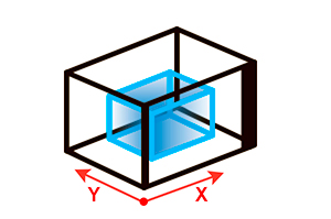
X/Y travel speed (mm/sec)
The X/Y travel speed is the linear speed of print head movements in XY plane without extrusions.
Leave a Reply Cancel reply
You must be logged in to post a comment.

- Opto-Mechanics
- Light Analysis
- Tables & Isolation
- Vacuum Instruments
- Special Offers
- Manual Positioning
- Manual Linear Stages
- Manual Rotation Stages
- Manual Goniometric Stages
- Manual Vertical Positioners
- Manual Tilt Platforms
- Motorized Positioning
- Screw Drive Motorized Linear Stages
- Direct Drive Linear Motor Stages
- Motorized Vertical Stages
- Motorized Rotation Stages
- Motorized Goniometric Stages
- Piezo Linear Stages
- Alignment Stages
- Fiber Alignment Stages
- Device Alignment Stages
- Motorized Fiber Alignment
- Fiber Positioning Mounts
- Fiber Coupling Fixtures
- Adjustors & Actuators
- Adjustment Screws
- Micrometer Heads
- Motorized Actuators
- Piezo Linear Actuators
- Piezo Stack Actuators
- Piezo Rotary Actuators
- Motion Controllers
- XPS Multi-Axis Controllers
- ESP302 3-Axis Controllers
- SMC100 1-Axis Controllers
- Piezo Controllers
- Controller & Stage Kits
- High Precision Hexapods
- High Accuracy Hexapods
- High Load Hexapods
- Vacuum Compatible Hexapods
- Hexapod Motion Controllers
- Industrial Motion
- Custom Motion Solutions
- Vacuum Compatible Motorized Positioners
- Mirror Mounts
- Kinematic Mirror Mounts
- Motorized Mirror Mounts
- Gimbal Mirror Mounts
- Flexure Mirror Mounts
- Fixed Mirror Mounts
- All Optical Mirror Mounts
- Optic Mounts
- Lens Mounts
- Optic Rotation Mounts
- Motorized Rotation Mounts
- Optical Filter Mounts
- Prism Mounts
- All Optical Mounts
- Optical Posts
- 0.31 in. Optical Post Assemblies
- 0.5 in. Optical Post Assemblies
- 0.7 in. Optical Pedestal Assemblies
- 1.0 in. Optical Post Assemblies
- 1.5 in. Optical Post Assemblies
- Optical Post Platforms
- Base & Brackets
- Base Plates
- Base Positioners
- Angle Brackets
- Optical Breadboards
- Solid Aluminum Breadboards
- Honeycomb Core Breadboards
- Composite Core Breadboards
- Breadboards with Microlocks
- Breadboard Accessories
- Optical Rails
- 19 mm Dovetail Rails
- 26 mm Steel 4-Sided Rails
- 48 mm Aluminum 4-Sided Rails
- 76 mm Quick Release Rails
- 95 mm Structural Rails
- 100 mm Dovetail Rails
- Beam Routing
- Optics Cage Plus
- Aegis Qube System
- Lens Tube System
- A-Line Lens Alignment System
- Optical Periscopes
- Lab Supplies
- Custom Component Solutions
- Plano-Convex Lenses
- Plano-Concave Lenses
- Achromatic Lenses
- Aspheric Lenses
- Objective Lenses
- Broadband Dielectric Mirrors
- Broadband Metallic Mirrors
- Laser Line Mirrors
- Ultrafast Mirrors
- Parabolic Mirrors
- All Mirrors
- Optical Filters
- Bandpass Filters
- Longpass Filters
- Shortpass Filters
- Neutral Density Filters
- Dichroic Filters
- All Optical Filters
- Beamsplitters
- Cube Beamsplitters
- Plate Beamsplitters
- Beam Samplers
- Polka Dot Beamsplitters
- Dichroic Beamsplitters
- Linear Polarizers
- Zero Order Waveplates
- Multiple Order Waveplates
- Achromatic Wave Plates
- Variable Wave Plates
- All Polarizers
- Optical Systems
- Laser Beam Expanders
- Faraday Optical Isolators
- Spatial Filters
- Laser Beam Attenuators
- Laser Beam Steering
- All Optical Systems
- Diffraction Gratings
- Plane Ruled Gratings
- Plane Holographic Gratings
- Echelle Gratings
- Transmission Gratings
- Concave Ruled Gratings
- Concave Holographic Gratings
- Optical Windows
- Fiber Optics
- Optic Accessories
- Custom Optics Solutions
- Spectra-Physics Lasers
- New Focus Tunable Lasers
- Laser Diode Modules
- HeNe Lasers
- Fiber-Coupled Laser Sources
- Laser Safety Glasses
- Incoherent Sources
- Solar Simulators
- Arc Lamp Sources
- QTH Light Sources
- Infrared Light Sources
- Tunable Light Sources
- All Incoherent Sources
- Laser Diode Control
- Laser Diode Drivers
- Laser Diode Controllers
- Temperature Controllers
- Modular Laser Diode Controllers
- Laser Diode Mounts
- All Laser Diode Control
- Accessories
- Lab Safety Products
- Flange Mount Accessories
- Light Routing Shields
- Beam Viewers
- All Light Source Accessories
- Solar Cell Test Systems
- Optical Meters
- Benchtop Power & Energy
- Handheld Power & Energy
- Meter & Sensor Kits
- Virtual Power & Energy
- Wavelength Meters
- Radiometers
- Optical Sensors
- Photodiode Power Sensors
- Thermopile Power Sensors
- Integrating Spheres
- Low Light Sensors
- All Optical Sensors
- Optical Receivers
- Fiber-Optic Receivers
- Free Space Receivers
- Balanced Receivers
- Fiber-Optic Detectors
- Free Space Detectors
- Spectroscopy
- Monochromators
- Spectroscopy Accessories
- Beam Characterization
- Beam Position Detectors
- Autocorrelators
- New Optical Sensor Finder
- New Optical Receiver Finder
- Optical Tables
- Active Damped SmartTables
- Passive Damped Optical Tables
- Optical Table Supports
- Optical Table Accessories
- Pneumatic System Components
- Optical Table Systems
- Isolated Integrity VCS Systems
- Rigid Integrity VCS Systems
- Isolated SmartTable Systems
- Rigid SmartTable Systems
- Table System Accessories
- Optical Workstations
- Isolated Vision IsoStations
- Rigid Vision IsoStations
- Workstation Accessories
- Vibration Isolators
- Elastomeric Isolators
- Mechanical Isolators
- Air Isolator Mounts
- Compact Pneumatic Isolators
- Isolation Platforms
- Elastomeric Isolation Platforms
- Mechanical Isolation Platforms
- Microscope Isolation Platforms
- Pneumatic Isolation Platforms
- Custom Vibration Isolation Solutions
- Vacuum Fittings & Flanges
- Granville Phillips Vacuum Gauges
- Mass Flow Controllers
- Pressure Control & Valves
- Mass Spectrometers
- ILX Lightwave®
- Oriel® Instruments
- Richardson Gratings™
- Spectra-Physics®
- MKS Instruments
- Specialty Industrial
- Electronics & Packaging
- Semiconductor
- Life and Health Sciences
- Scientific Research
- PCB Manufacturing
- Flat Panel Display Manufacturing
- LED Manufacturing
- Solar Panel Manufacturing
- Lithium-Ion Battery Manufacturing
- OLED Manufacturing
- Technical Notes
- Application Notes
- Selection Guides
- Technical Articles
- Industry Links
- Technical Support
- Service & Returns
- Trade Shows & Events
- Company Information
- About Newport
- Company Overview
- Press Releases
- Quality Commitments
- Contacts & Locations
- Corporate Headquarters
- Worldwide Sales & Service
- Legal Information
- CA Transparency in Supply Chains
- Terms & Conditions of Sale
- Patent Information
- Terms of Use
- Privacy Policy
- Supplier Information
- Supplier Code of Conduct
- Terms & Conditions of Purchase
Product Comparison
- Shopping cart items Shopping cart items
- Submit search
- Motion Control
- Linear Translation Stages
- One-XY Integrated Linear Motor XY Linear Stages
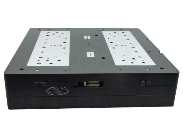
Motorized XY Linear Stage, Linear Motor, 50 mm Travel

Model: ONE-XY60
Add to list.

Product Series Overview
The ONE-XY60 is an integrated XY linear motor stage designed to eliminate the integration of individual X and Y stages and increase system stiffness for dynamic applications. It features a travel range of 50 mm, with precise orthogonality alignment between the X and Y axes. This stage utilizes robust components such as its iron-less motor drive and cross-roller bearings to deliver high performance, making them ideal solutions for precision industrial applications such as semiconductor wafer inspection, microelectronics test and assembly, metrology, laser microprocessing.
For cable management options please contact our applications team.
Micron-level Straightness and Flatness
Because of the ONE-XY's precision grinding and cross-roller bearings, it achieves micron-level straightness and flatness.
Ironless Linear Motor
The high efficiency, ironless linear motor has the advantage of higher speed, acceleration and system responsiveness without wear to motor brushes or drive screws, significantly reducing heat generation. Additionally the non-cogging feature of the Ironless Linear Motor ensures excellent speed stability. Not only does the ironless motor provide these advantages, it also results in high-throughput and high reliability.
Integrated X and Y Axes
The ONE-XY's most distinguishing feature is its 3 plate design, allowing movement in both X and Y direction with a low profile relative to stacked stages. Orthogonality is built into the design, therefore enhancing the XY accuracy.
Specifications
Technical specs.
- Motorized Axes XY
- Travel Range 50 mm
- Maximum Speed 200 mm/s
- Minimum Incremental Motion 50 nm
- Maximum Acceleration 0.3 G
- Continuous Motor Force 10 N
- Peak Motor Force 21 N
- Centered Load Capacity 100 N
- Accuracy, Typical ±0.4 µm
- Accuracy, Guaranteed ±1.5 µm
- Bi-directional Repeatability, Typical ±0.040 µm
- Bi-directional Repeatability, Guaranteed ±0.070 µm
- Flatness, Typical ±0.5 µm
- Straightness, Typical ±0.5 µm
- Orthogonality 96 µrad
- Pitch, Typical ±15 µrad
- Pitch, Guaranteed ±55 µrad
- Yaw, Typical ±15 µrad
- Yaw, Guaranteed ±55 µrad
- Roll, Typical ±29 µrad
- Drive Type Linear Motor
- Origin Repeatability ±0.1 µm
- Cable Length 3 m
- Width 125 mm
- Weight 2.9 kg
- MTBF 20,000 h (25% load, 30% duty cycle)
- Compliance RoHS 3, CE
Resources & Downloads
- Mini Laser Machining Brochure 2016 (1.4 MB, PDF)
- ONE-XY Data Sheet.pdf (1.3 MB, PDF)
- Laser Machining Brochure 2018 (3.4 MB, PDF)
2D / 3D CAD Software
- Download CAD Files
Drawings And Cad
- ONE-XY60 (386.5 kB, PDF)
- ONE-XY - User's Manual (1.4 MB, PDF)
Related Products
Compatible controllers and driver card.
Two driver cards and two encoder adapters are required to run a two-axis ONE-XY stage when used with XPS-D or XPS-RLD controller.
ONE-XY60 - Drawings & CAD
ONE-XY60 - Drawings
Need a new account, password reset, email verification required, cart items updated, remove product, check order status, sign in required, add to cart, also available on newport.com.

Invalid VAT ID
XY tables, commonly referred to as XY positioning tables, XY linear tables, or motorized XY tables, are used in linear positioning applications to position a sample (slides, flow cells, well plates, etc.) being imaged or analyzed under a microscope. With the ability to move in two degrees of freedom, XY tables enable the imaging of the entire sample with high precision and efficiency.
We offer many different travels and approaches to XY motion depending on your specific application.

High Performance XY Tables

Open Frame XY Tables

Monolithic High Load XY Tables

Custom Designed XY Tables

Compact High Performance XY Tables
Compact, high performance XY linear tables utilize stacked individual axes to create XY motion. Crossed roller bearing stages such as the SmartStage XY and MMX offer better stiffness and repeatability but have limited travel. Alternatively, the MMS series linear guide rail and carriage bearing assembly offers longer travels with slightly less repeatability.

SmartStage™ XY
The SmartStage ™ XY linear positioning table offers high precision and includes an embedded controller inside the table.

The MMX™ series miniature linear table delivers excellent mechanical and servo stiffness with a low profile design.

The MMS ™ miniature linear XY table has a low profile, stackable, shuttle style design ideal when longer travel is required.
Open frame XY positioning tables have an open aperture that allows for illuminating a sample from one side with the camera, optics, and objective on the other side of the sample. This arrangement is referred to as non-epifluorescence imaging. A typical microscope would have the illumination source below the sample and the camera/detector above the sample, while an inverted microscope has the opposite arrangement with the camera and objective below the table. Having a clear aperture is helpful as it takes up less space than cantilevering the sample.

The XYMR ™ open frame microscope stage offers exceptional flatness, straightness, and accuracy. Ideal for cell counting and analysis.

The OFL™ series motorized XY microscope table provides increased travel and load bearing capacity in an open frame XY configuration.

The DDM™ series direct drive microscope table provides quiet motion with the best accuracy and repeatability of the open frame series.
Monolithic High Load XY Linear Tables
Monolithic style XY linear tables are used for larger loads and when there is a need to reduce height. The middle plate is both the table of the lower axis as well as the base of the upper axis. By using a monolithic integrated approach, a stiffer overall motion table design is achieved which allows for a lower overall stack height, which helps minimize Abbe errors getting introduced into the accuracy of the motion.

The XYR™ positioning stage is our most popular linear stage and uses a lead screw for motion. The monolithic integrated XY center makes the table stiff and compact.

The XYRB™ series incorporates a ball screw for more precise and repeatable positioning. The encoder option provides high precision.

The XYA™ offers an enclosed table structure with embedded cables, motor, and controller for a cleaner appearance and less external cabling.
Custom Design Capabilities
Dover Motion has more than 25 years of experience working with OEMs to optimize motion for objective focusing, and moving samples on a slides, well plates, or flow cells. Our engineers have developed unique motion control architectures for precision motion specifically tailored to the needs of OEMs developing microscope-based systems and instruments relying on optical imaging as the analytical detection technique. Dover Motion’s novel, patented, SmartStage embedded controls provides key packaging advantages, reduced cabling and cable management requirements, and incredible system value for our clients.

Open Frame (XY) Tables
- Fast Linear Motors
- Built in controller
- High Resolution encoder feedback

XY + Tip Tilt Tables
- Long travel high speed load / unload stage
- Precision stepping axis
- Tip / Tilt to compensate for slide variation

Well Plate XYZ Tables
- Optimized for price/performance
- Linear Motor high speed stepping axis
- Screw based indexing and Z lift axes
- Standard well plate carrier
See How We are Disrupting Motion Control

Additional Resources

About XY Tables
How do xy tables work.
While a number of positioning actuator applications can be addressed with single-axis translation stages, the majority of customer payloads require motion in two axes, for which we use an XY table, also called XY positioning table, XY linear table, or motorized XY table. In its simplest configuration, an XY table can be assembled by simply bolting two single-axis stages together. In that case, care must be taken to ensure that the axes are truly orthogonal.
What is a Monolithic XY Table?
In a monolithic XY table, the orthogonality is precision-machined into its component parts. In this type of table, the top of the lower axis serves as the base for the upper axis in a simple and compact three-piece design. This approach typically reduces the overall height of the XY table resulting in less Abbe error. In addition, most of our actuators can be mounted in an XYZ configuration for vertical applications.
What Type of Mechanical Guideways Are Used in XY Tables?
XY linear tables can be designed with a wide range of guideways, including:
- Ball and pressure plate provide lower cost, but less stiffness
- Crossed roller guideways offer high stiffness and precision straightness across travel
- Recirculating profile rails are best for longer travels
- Air bearings provide the highest precision flatness and straightness
What Type of Mechanical Actuation is Used in the XY Tables?
Dover Motion offers various actuation options, including:
- Rotary stepper motor or rotary servo motor driving a lead screw and friction nut for low cost applications
- Rotary stepper motor or rotary servo motor driving a ball screws for better repeatability
- Rotary motor driven belts and pulleys where speed and cost is more important than precision
- Linear motors for the best reliability (non-contact with no wearing elements) and for high precision repeatability
XY linear stages with air bearings and linear motors provide some of the highest levels of performance available. The only assembly more precise is called a planar gantry design.
Let's talk about your next project.
Thank You For Requesting Access
To view the requested file, please click the button below.
- DOF-5 : 5mm travel
- SmartStage Z-50 : 50 mm travel
- SmartStage Linear : 50-200 mm travel
- MMS Linear Shuttle : 200+ mm travel
- SmartStage XY : 50-200 mm travel
- SmartStage XYM : 50-75 mm travel
- XYR : Screw Driven
- Capabilities
- Motion Solutions
- Custom Stages
- Automated Microscope Concepts for Fluorescence Imaging
- Microscope Calculations Explained: FOV, DOF, NA
- Automated Digital Microscopes & Optics Optimization
- Calculate Digital Microscope Magnification, Field Of View, Image Size, and Resolution
- Next Gen Sequencing (NGS)
- Precision Motion Control
- Automated Liquid Handling
- Microscopy Videos
- Case Studies
- White Papers
- Motion Control Handbook
- Piezo Actuators
- Software & Manuals
- CTO Spotlight: Kevin McCarthy
- History of Innovation
- Certifications
- Request A Quote
- Technical Support
- Repair & Return
- Directions & Accomodations
Dynamic title for modals
Are you sure.
COMMENTS
X/Y Axis Movement Speed Questions. I'm doing 0.1 layer height prints on my Dremel Idea Builder and normally have the base speed at 30mm/s with outlines at 60% for the best quality with reduced ringing, etc. The X/Y rapid movement speed defaults to 120mm/s but I'm wondering if I should try lowering that to around 80mm/s to avoid vibrations and ...
M201 F60 S47. If the X or Y axis wants to change direction again within 1/60th of a second, reduce the speed by up to 53%. Set the max acceleration for one or more axes (in current units-per-second per-second). The acceleration limit for extruder (s) only applies for print moves where at least one other axis is also in motion.
First is the G-code command and in this case that's the G01 which means "move in straight line to a specific position".; We declare the position or the coordinates with the X, Y and Z values.; Lastly, with the F value we set the feed rate, or the speed at which the move will be executed.; To wrap up, the line G01 X247.951560 Y11.817060 Z-1.000000 F400 tells the CNC machine to move in a ...
For your Jerk setting you should try 7mm/s and see how it goes. Jerk X & Y should be at 7. Acceleration for X, Y, Z should be set to 700. You can go directly into your menu on your printer, select the control setting, then 'motion' you should see your acceleration and jerk settings. Vx - 7.
Travel speed and print speed are different, and you probably meant print speed. Flow [mm 3 /s] = line width x layer height x print speed. So your flow currently is 10.4 mm 3 /s, which is about what you can expect from the stock hotend (8-12 mm 3 /s). Yes I meant print speed and realised my mistake, but couldn't edit the title so hoped it would ...
Set the XY travel speed between probe points. [V<0-4>] Set the verbose level [W<bool>] Write a mesh Z offset. Use X,Y or I,J to specify the point. Use Z to specify the new value to set. [X<float>] Specify X when setting a mesh value (PROBE_MANUALLY). [Y<float>] Specify Y when setting a mesh value.
This setting is a ratio. When set to 0%, the flow rate will be adjusted, while at 100%, the print speed is adjusted. Values between 0% and 100% combine the two. If this ratio exceeds 100%, the flow rate is reduced to produce thicker lines but the speed is reduced more to compensate.
I realized, the travel speed is lower than the feed rate. Feed rate was set via Estlcam to 15mm/s. I created a gcode file with Estlcam and ran it from SD-Card via LCD. Loocking in Configuration.h from Marlin I found XY_TRAVEL_SPEED = 8000mm/min (133mm/s) but my travel speed is definitely much lower! I don't yet have endstops and tried the set ...
The L-731, L-738, and L-741 XY stages work with velocities to 90 mm/s. It is possible to use either stepper or DC motor to drive the precision ball screws. The two-phase stepper motors also generate a high torque at lower velocities; the DC motor variants are recommended for applications that require high running smoothness and higher ...
If your 3D printer can handle it, you can also try increasing the XY travel speed on the Speeds tab of your Simplify3D process settings. This allows the printer to make faster movements, which means less time for oozing. For other tips on how to prevent stringing and oozing, please refer to our Print Quality Guide which has an entire section ...
Manufacturer of 1…6-axis Positioning Systems, Motorized 2-DOF XY-Stages (XY-positioning tables) Motorized High Precision XY Linear Stages, X-Y Positioning
Limit max. print/travel speed to 40 mm/s? Although the MK3 is a quiet printer, I need to limit its speed to below 40 mm/s in order to be nighttime compatible. Above 40 mm/s, from one firmware revision on there are some annoying resonances, making it noisy again. So how do I most efficiently limit X/Y speeds (print and travel) to 40 mm/s?
Dover Motion offers a variety of standard XY stages, including translation and linear. ... Linear Stages. SmartStage™ Linear: 50-200 mm travel; MMS Linear Shuttle: 200+ mm travel - View All; XY Stages. SmartStage™ XY: 50-200 mm travel; SmartStage™ XYM: 50-75 mm travel; XYR: Screw ... Long travel high speed load / unload stage; Precision ...
Posted December 22, 2020 · Travel speed limited to 300mm/s. cura 4.8.0. Profile Voron2 350. Travel speed setting > 300mm/s is marked red and slicing is not possible. Allready checked the the printer settings with the extension from the markedplace. max-X/Y = 2997924580mm/s. Printspeed > 200mm/s creaes also a warning.
SmartStage™ XY: 50-200 mm travel; SmartStage™ XYM: 50-75 mm travel; XYR: Screw Driven - View All; Rotary Stages. RTR ... (X, Y, Z, roll, pitch, and yaw) of the payload to only one, producing motion along a straight line. ... Using a linear motor is generally considered to be optimal for high speed motion systems and is the most precise ...
The Z-Speed Factor is used to set the real-time Z-axis travel speed as a percentage of the real-time XY travel speed. This makes it so that the Z-axis motor can move faster when the XY speed is faster, but also slow down when the XY speed gets slower such as around tight corners or small holes. This feature allows the torch to react to sudden ...
X/Y travel speed (mm/sec) December 21, 2018 December 21, 2018 Manfret Settings Review The X/Y travel speed is the linear speed of print head movements in XY plane without extrusions.
There's no reason to limit travel speed. Remember these machines are originally designed to print PLA at 50-60mm/s and 500mm ss with Marlin firmware. The stock 42-34 motors are plenty for that specification. With the quality limitations imposed by mechanical resonance, and extruder over-pressure, going much faster than those figures massively ...
to convert this to plasma code you will need to search for the M3 lines and replace with your touchoff code and then the M3 line again, thus inserting the touchoff code before all the M3 lines. My x and y speeds on my plasma table are not following the gcode. I cut a 60mm diameter circle and it takes 27 seconds.
Product Series Overview. One-XY Integrated Linear Motor XY Linear Stages. The ONE-XY60 is an integrated XY linear motor stage designed to eliminate the integration of individual X and Y stages and increase system stiffness for dynamic applications. It features a travel range of 50 mm, with precise orthogonality alignment between the X and Y axes.
SmartStage™ XY: 50-200 mm travel; SmartStage™ XYM: 50-75 mm travel; XYR: Screw Driven - View All; Rotary Stages. RTR - View All; Motion Control Systems. ... Long travel high speed load / unload stage; Precision stepping axis; Tip / Tilt to compensate for slide variation; Learn More. Well Plate XYZ Tables.