- Switch skin
Home > Protection > Tripping Curves of Circuit Breakers – B, C, D, K and Z Trip Curve

Tripping Curves of Circuit Breakers – B, C, D, K and Z Trip Curve
Types of circuit breaker based on its tripping curve.
A circuit breaker is a protection device employed in every electrical circuit to prevent any potential hazard. There are different types of circuit breakers used all over the world due to their various characteristics & applications. It is necessary to have a circuit breaker that offers adequate protection so that one can work safely around it without having fear of any potential hazards. That is why it is best to know about these kinds of circuit breakers & what kinds of protection do they offer before buying one.
Table of Contents
What is a Circuit Breaker?
A circuit breaker is an electrical device that provides protection against fault current. It breaks the circuit in case of overloading & short circuit. The fault currents generated due to these fault conditions can damage the electrical devices as well as cause fire in a building that can also pose danger to human life.
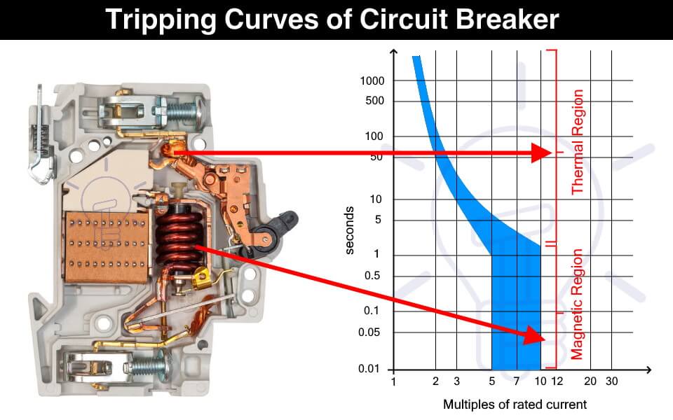
The circuit breaker instantly cut off the power supply to reduce further damage. A circuit breaker has two types of tripping unit i.e. thermal and magnetic tripping unit.
Thermal Tripping Unit: the thermal tripping unit is used for protection against overloading. It uses a bi-metallic contact that bends with a change in temperature. The current flowing through the bimetallic strip heats up contact & trip the circuit breaker.
The rate of bending of the bi-metallic strip depends on the amount of current. Therefore, greater the overloading current, faster the circuit breaker trips.
Magnetic Tripping Unit: The magnetic trip unit is used for protection against short circuit current. it includes a solenoid that produced a strong magnetic field due to high short circuit current to instantly trip the circuit breaker.
Related Posts:
- MCB (Miniature Circuit Breaker) – Construction, Working, Types & Applications
- MCCB (Molded Case Circuit Breaker) – Construction, Types & Working
What is a Trip Curve?
A trip curve also known as a current time graph is a graphical representation of the response of a circuit breaker. It shows the current relationship with the tripping time of a protection device.
Why We Need Different Tripping Curves?
Circuit breakers are used for tripping the power supply as quickly as possible in case of overcurrent. But it should not trip so fast & unnecessary that it becomes a problem.
The overcurrent can happen under normal conditions such as the inrush current of a motor. Inrush current is the huge current draw during the starting of a motor that causes voltage dips in the main line. The circuit breaker should be able to tolerate the inrush current & it should provide some delay before tripping.
Therefore, the circuit breaker selected should not trip so fast that it creates a nuisance & it should not trip so late that it causes any damage. This is where the tripping characteristics of the circuit breakers come into play.
The tripping curve tells how fast a circuit breaker will trip at a specific current. The different tripping curves classify the circuit breakers into categories where each category is used for specific types of loads. It is essential to select a circuit breaker that provides the necessary overcurrent protection.
- Types of Circuit Breakers – Working and Applications
- Air Circuit Breaker (ACB): Construction, Operation, Types and Uses
How to read a Trip Curve?
The following figure shows a chart of a trip curve.
The horizontal X-axis represents the multiples of the current flowing through the circuit breaker. While the Y-axis represents the tripping time of the circuit breaker on a logarithmic scale.

The thermal region shows the response of the bimetallic contact trip unit during overcurrent. The curve shows that the circuit breaker’s tripping time reduces with an increase in the current. The first curve in the graph shows the response of a thermal trip unit.
While the magnetic region shows the response of the solenoid to fault current such as a short circuit current.
As seen from the graph, a circuit breaker does not have a fixed tripping time and we cannot predict an exact tripping point. It is because the tripping is affected by ambient conditions such as temperature. Think of it as a Schrödinger’s Cat area, we do not know when the tripping will occur unless the event happens.
Types of Circuit Breaker Based on Tripping Curves
The circuit breakers are classified into the following five types based on their tripping curves.

Such type of circuit breaker is designed to instantly trip when the operating current is 3 to 5 times its rated current. Their tripping time falls between 0.04 to 13 seconds. They are suitable for domestic applications where surges are very low such as lighting & resistive loads.

They are sensitive and must not be used in places where the normal surges keep on tripping it unnecessarily.
Type C circuit breaker trips instantly at current surges 5 to 10 times its rated current. its tripping time lies between 0.04 to 5 seconds. As they can tolerate higher surge currents, they are used in commercial applications such as the protection of small motors, transformers, etc.

Type D circuit breaker trips instantly when operating current reaches 10 to 20 times its rated current. Its tripping time is 0.04 to 3 seconds. Such circuit breakers can tolerate the high inrush current of large motors. Therefore, they are suitable for running heavy loads in industrial applications.

Such type of circuit breakers trips at 10 to 12 times its rated current with a tripping time of 0.04 to 5 seconds. These circuit breakers are also used for heavy inductive loads in industrial applications.

Type Z circuit breakers are the most sensitive circuit breaker that instantly trips when the operating current reaches 2 to 3 times its rated current. They are used for sensitive equipment that requires very low short circuit trip settings.

- Main Difference between Fuse and Circuit Breaker
- Difference Between MCB, MCCB, ELCB and RCB, RCD or RCCB Circuit Breakers
- How to Read MCB Nameplate Data printed on it?
- How to Find the Proper Size of Circuit Breaker? Breaker Calculator and Examples
- HVDC Circuit Breaker – Types, Working and Applications
- Can We Use AC Circuit Breaker for DC Circuit and Vice Versa?
- Electronic Circuit Breaker – Schematic and Working
- Smart WiFi Circuit Breaker – Construction, Installation and Working
- Why Circuit Breaker Capacity Was Rated in MVA and Now in kA and kV?
- How to Wire 120V and 240V Main Panel? Breaker Box Installation – US – NEC
- How to Wire Single-Phase, 230V Consumer Unit (Breaker Box) with RCD? IEC, UK and EU
This Post has been published by WWW.ELECTRICALTECHNOLOGY.ORG.
Electrical Technology
Related articles.

A Complete Guide About Solar Panel Installation. Step by Step Procedure with Calculation & Diagrams

How to Calculate the Battery Charging Time & Battery Charging Current – Example

Automatic UPS / Inverter Connection Diagram to the Home Panel Board

How to Find the Proper Size of Wire & Cable: Metric & Imperial Systems

Automatic Street Light Control Circuit using LDR & Transistor BC 547

Emergency LED Light Circuit – DP-716 Rechargeable 30 LED’s Lights Schematic
One comment.
Do we have to consider the tripping curves for DIY installation?
Leave a Reply Cancel reply
Your email address will not be published. Required fields are marked *

- Engineering & Technology
- Electrical Engineering
GE Spectra RMS TCC Trip Curves (2010-05)
")
Add this document to collection(s)
You can add this document to your study collection(s)
Add this document to saved
You can add this document to your saved list
Suggest us how to improve StudyLib
(For complaints, use another form )
Input it if you want to receive answer
Power Sponsor
Breaker curves.
Add your listing here
AE1A, AE1B, AL2 BRKR - L
AK175, AK1100 Breaker EC1 SERIES TRIP DEVICE - LS (1BB, 1CC, 2AA, 2BB, 2CC)
AK215, AK225 Breaker - LI
Long-Time Delay, Short-Time Delay, and Instantaneous Time-Current Curves - Type WavePro with Enhanced MicroVersaTrip Plus, MicroVersaTrip PM (Series RMS-9D), or Power+ Digital RMS Trip Units
Ground Fault Time-Current Curves - Type WavePro with Enhanced MicroVersaTrip Plus, MicroVersaTrip PM (Series RMS-9D), or Power+ Digital RMS Trip Units
GROUND FAULT CURVE FOR PROTRIP TRIP UNIT
LONG TIME DELAY, SHORT TIME DELAY AND INSTANTANEOUS CURVES FOR PROTRIP TRIP UNIT
AK15, AK25, AK50, AKT50 BRKR EC1 SERIES TRIP DEVICE - LSI
AK75, AK100 BRKR EC1B SERIES TRIP DEVICE - LI (1BB-3)
AK75, AK100 BREAKER EC1B SERIES TRIP DEVICE - LI (1CC-3)
AK75, AK100 BRKR EC1B SERIES TRIP DEVICE - LSI
AK15, AK25, AK50 BRKR EC2 & EC2A SERIES TRIP DEVICE - LI (IA3)
AK15, AK25, AK50 BRKR EC2 & EC2A SERIES TRIP DEVICE - LI (1B3)
AK15, AK25, AK50 BRKR EC2 & EC2A SERIES TRIP DEVICE - LI (1C3)
AK15, AK25, AK50, AK75, AK100 BRKR POWER SENSOR TRIP DEVICE - LI
AK25, AK50, AK75, AK100 BRKR PS1 & PS1A POWER SENSOR TRIP - LSI
AK25, AK50, AK75, AK100 BRKR PS1A POWER SENSOR TRIP - GROUND
AK75, AK100, AKR30, AKR50, AKRT50 BRKR ECS TRIP DEVICE - LSI
AK75, AK100, AKR30, AKR50, AKR75, AKR100, AKRT50 BRKR ECS TRIP DEVICE - LSI
Page 1 of 6
The basics of trip curves for panel builders
A critical but often confusing characteristic of miniature circuit breakers are trip curves. Knowing the basics of trip curves can ensure selecting the lowest-cost breaker that will provide the needed protection without nuisance tripping.
To the average consumer, circuit breakers are basic on/off devices that trip when they detect incoming current above the rated threshold. Panel builders, however, understand that breakers operate in a far more sophisticated way considering multiple variables: variables that can be represented graphically in a trip curve that shows the range of conditions that will initiate a trip.
Selecting the optimum miniature circuit breaker (MCB) is critical to helping ensure proper protection, with minimal or no nuisance tripping, at the lowest possible cost. Matching a breaker to an application requires an understanding of the basics of trip curves.
Molded-case versus miniature circuit breakers
Almost every electrical-protection device operates based on a simple formula: If THIS, then THAT. Some large, molded-case circuit breakers can be adjusted to adapt the breaker to the application, reacting to THIS variable with the appropriate THAT response.
This adjustability enables panel builders to select a molded-case breaker with the required specifications – plus a “safety factor” to account for application unknowns or future equipment changes – and then “tune” the breaker once it’s in use.
MCBs, on the other hand, operate based on only two parameters that cannot be adjusted: overload and short-circuit. Even with just these two basic parameters, though, breaker buyers have a broad selection of MCBs that could potentially meet their application requirements. Selecting the appropriate breaker includes considering not just features like amperage, voltage, and interrupting rating, but also trip curves.
Trip curve basics
Most protective devices have a defined trip curve, also referred to as a time/current curve, that describes their behavior. The curve is represented in a graph showing how the breaker will respond to changes in current, basically the high- and low-current thresholds, that will cause a trip.
The optimum trip curve balances overcurrent protection and machine operation. A fast-acting trip curve will do an excellent job of protection, but at the cost of frequent and costly nuisance tripping (mostly due to inrush currents of motors and transformers). A breaker with higher trip points will better keep the process up and running.
Trip curves are defined by IEC standards 60898-1 and 60947-2. The curves represent two different trip functions: thermal and electromagnetic. The thermal section (top/red area of the chart) that responds to overloads typically consists of a bi-metallic strip. The thermal trip unit responds relatively slowly and is consistent across all trip curves.
The short-circuit section (bottom/grey) relies on a magnetic coil or solenoid that opens when the overcurrent’s design limit is reached. This section of the breaker responds within milliseconds. This characteristic of the trip curve has no counterpart on the UL side.
The concept of trip curves originated in the IEC world, and the alphabetic code used to categorize MCBs carried over from IEC standards. They define the lower and upper thresholds for tripping (no-trip threshold and trip threshold). The trip-curve graph shows the tolerance band within which manufacturers can set the individual tripping point of their breakers.
The characteristics of the magnetic/short-circuit trip unit and applications of each curve, from most- to least-sensitive are: Z: Trips at 2 to 3 times rated current. Suitable for highly sensitive applications, e.g., semiconductor devices. B: Trips at 3 to 5 times rated current. C: Trips at 5 to 10 times rated current. Suitable for medium inrush currents. K: Trips at 10 to 14 times rated current. Suitable for loads with high inrush currents, mostly for use with motors and transformers. D: Trips at 10 to 20 times rated current. Suitable for high starting currents.
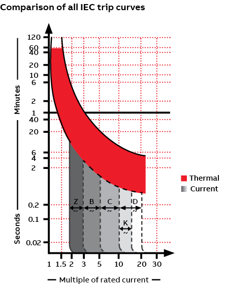
Referring to the graph above, you can see that higher currents trigger more rapid trips.
The ability to tolerate inrush current is an important consideration in trip-curve selection. Certain loads, notably motors and transformers, experience a momentary change in current – the inrush current – at contact closure. Faster protective devices, like a B-trip curve, would see this inrush as a fault and open the circuit. For these types of loads, trip curves with a higher magnetic tripping point, either D or K, can “ride through” the momentary inrush of current, protecting the circuit without nuisance tripping.
Choosing the right trip curve
Experienced panel builders can often identify the appropriate trip curve for various applications but may require some trial and error to arrive at the optimum breaker. For many panel builders, though, the best approach may be to consult with your device manufacturer or distributor. Provide them with the details of your application, and they should be able to recommend the right miniature circuit breakers to meet your needs.
See related blog post “Choose enhanced breaker and controller options to build more-competitive panels” .
Thomas Weinmann
Senior Product Marketing Manager
ABB Electrification Business
Presented by:
This site is created by ABB application engineers and experts as an educational tool to help engineers.

Power Break II

Power Break* II Insulated Case Circuit Breakers are highly compact, heavy-duty breakers that combine ease of use, aesthetics and state-of-art performances in 200 through 4000-Amp frame sizes, rated for up to 200,000 Amps RMS symmetrical for 240Vac, in drawout and stationary versions.
Now available with the new EntelliGuard* TU Trip Unit which provides excellent selectivity and arc flash energy protection.
- NEW: Kits to put a Power Break II into a Stationary Power Break I space, See Instruction Manual DEH-41502
- For Drawout Applications, contact 888-GE4-SERV
Features & Benefits
- Compact, Lightweight design
- Modular, drop-in accessories common to all frame sizes
- Flush-Mounted pump handle
- Manually and electrically operated versions in same compact envelope
- Double Insulated ON/OFF buttons
- 72-point pre-wired , dedicated secondary terminals
- Modular, field-installable motor operator
- EntelliGuard TU Trip Unit featuring Reduced Energy Let-Through (RELT) setting
- Modular auxiliary switches with up to 12 NO/NC set of contacts
- Charge-after-close mechanism
- Manual discharge of springs without closing
- Suitable for reverse feed™
Related Industries

Related Products

Publications
- Application and Technical
- Catalogs and Buyers Guides
- Drawings-Outline and Dimensional
- Installation and Instruction
- Time Current Curves
- Circuit Breakers
- Molded Case Circuit Breakers
Spectra RMS™ Electronic Trip

View Larger
Representative Image

Your browser does not support iframes.
Catalog No. : SKLA36AT1200
Description: SKL 3P 600V 1200A
UPC: 783164211788
Email page to others
- Email Address
Email Address (For your convenience, you can send the page to up to three e-mail addresses at a time. Your e-mail address will be shown in the forwarded message.)
Note: ABB will only use the e-mail addresses you provide to forward this page. ABB will not distribute or use the email addresses to contact your colleagues again.
Message Sent
Your message has been sent successfully.
We're sorry
Your e-mail can not be sent at this time. Please try again later.
Specifications
- Publications
Descriptors
Classifications, sk (1200af); long/tracking short time instantaneous.
Publication No.: K215-178C
Publication Type: Time Current Curves
IMAGES
VIDEO
COMMENTS
www.geindustrial.com BuyLog™Catalog Time Current Curves and Outline Drawings Rev. 11/13 Data subject to change without notice Section 28 ™ ™ ™ ™™ ™ ™ ™ ™ ™ ™ ™
Spectra breakers are now in the Limited life cycle phase. For circuit breakers, see SACE® Tmax® XT MCCBs. For retrofits of existing equipment, see Tmax XT Retrofit Kits for Spectra Panelboards and Switchboards. ABB & GE Industrial's Electronic Trip Circuit Breaker Mold Case Distribution. Get all the power of ABB and GE Industrial electrical ...
Types of Circuit Breaker Based on Tripping Curves. The circuit breakers are classified into the following five types based on their tripping curves. Type B. Such type of circuit breaker is designed to instantly trip when the operating current is 3 to 5 times its rated current. Their tripping time falls between 0.04 to 13 seconds.
Fig. 4.3Typical time-current curve for Spectra RMS circuit breaker. 5 Spectra RMS Mag-Break product line The Spectra RMS Mag-Break motor circuit protector offers the precision and ambient insensitivity of GE's solid-state tripping system in a highly cost-effective motor circuit pro-tective device. The same interchangeable rating plugs are
There are a number of possible causes for these units to blow a fuse or trip a circuit breaker. For example, a shorted heater, timer, loose electrical wires or a failed component may cause this to happen. Unplug the appliance and replace the fuse or reset the breaker. If the fuse blows or breaker trips immediately, the fault is typically with ...
molded case circuit breakers. The trip unit design is based on the EntelliGuard trip unit platform. The microEntelliGuardTM Trip Unit incorporates many of the advanced features and protective functions available on the EntelliGuard Trip Unit and is available in the 600-amp Spectra G and 1200-amp Spectra K frames.
EntelliGuard* TU Trip Units Installation, Operation, and Maintenance Manual GE Industrial Solutions For UL/ANSI trip units used in the following circuit breakers and switches: • EntelliGuard G • WavePro • AK, AKR • Conversion Kits • Power Break* • Power Break* II • HPC* Switch, New Generation
GE Spectra RMS TCC Trip Curves (2010-05) 2-pole—480 Vac max. 3-pole—600 Vac max. Long-time delay; not adjustable. thermal and interrupting derating of the circuit breaker. Refer to Selection and Application manual. second. For additional data refer to lp and l t curves. 2-pole—480 Vac max.
Frame Selection® for Use with MicroVersaTrip PM or Plus Trip Units Circuit Breaker Envelope Size (Amps) 80 0 1600 2000 3000 4000 Circuit Breaker Frame Size (Amps) 800 1600 2000 2500 ... GE Insulated Case Circuit Breakers Features • High-dielectric strength, glass reinforced insulating case for ... rating at lower limit to trip time curve ...
A GE circuit breaker labeled with C16, meaning a C-curve breaker with a 16-ampere rating. Image used courtesy of the author . ... For the lower current curves, like B and Z, the trip time may be a bit longer, up to nearly 10 seconds and 30 seconds at a maximum, respectively. However, they are likely to open much more quickly than this maximum ...
Spectra RMS™ Breakers with MicroVersaTrip Plus™ Trip Units or MicroVersaTrip PM™ Trip Units—pages 4-32 to 4-35 and 4-47 to 4-65. Molded-Case Circuit Breaker and Switch Terminal Configuration Code Order standard Cu/AI lugs by using suffix codes presented. Order lugs separately if special lugs are required. For optional lugs, see page 4-62.
ground fault curve for protrip trip unit. year 1998. file size 74.98 kb. des-007 0 reviews. long time delay, short time delay and instantaneous curves for protrip trip unit. year 1998. file size 68.89 kb. ges-6000a 0 reviews. ak15, ak25, ak50, akt50 brkr ec1 series trip device - lsi. year.
Learn the basics of circuit breaker trip curves by understanding what they are and how we use them.Get the FULL video transcript here: https://www.rspsupply....
https://www.AutomationDirect.com/circuit-protection - (VID-CP-0009) Circuit breaker and fuse trip curves (CB Trip curves) explain how a trip occurs based on ...
A breaker with higher trip points will better keep the process up and running. Trip curves are defined by IEC standards 60898-1 and 60947-2. The curves represent two different trip functions: thermal and electromagnetic. The thermal section (top/red area of the chart) that responds to overloads typically consists of a bi-metallic strip.
Power Break* II Insulated Case Circuit Breakers are highly compact, heavy-duty breakers that combine ease of use, aesthetics and state-of-art performances in 200 through 4000-Amp frame sizes, rated for up to 200,000 Amps RMS symmetrical for 240Vac, in drawout and stationary versions. Now available with the new EntelliGuard* TU Trip Unit which ...
Spectra RMS Molded Case Circuit Breakers (SE150, SF250, SG600 and SK1200) have a digital, solid state, RMS sensing trip system with field installable, front-mounted rating plugs to establish or change the breaker ampere rating. Adjustable instantaneous with tracking short-time is standard on all frames. ... Time Current Curves. SK (1200AF ...