Understanding Fundamentals of Current, Voltage, and Resistance
Created and Edited by Kenneth (Alex) Jenkins - Fall 2023. Edited by Anshu Dendukuri - Spring 2024
The central concept in understanding the fundamentals of current, voltage, and resistance is unraveling the essential principles that govern the flow of electric charge. Current represents the rate of this flow, voltage signifies the driving force behind it, and resistance encapsulates the opposition encountered in the circuit. A grasp of these fundamentals is crucial for navigating the intricacies of electrical systems and technology.
- 1 Ohm's Law
- 4 Resistance
- 5.1 Examples of the Water/Pipe Analogy
- 6 Connectedness to Applications Outside of Physics
- 7 Initial vs Steady State
- 9.1 Further reading
- 10 References
Ohm's Law , a fundamental principle in electrical engineering, establishes a foundational relationship between resistance, voltage, and current in a circuit. Named after the German physicist Georg Ohm , the law states that the current passing through a conductor between two points is directly proportional to the voltage across the two points, given a constant temperature. Mathematically expressed as [math]\displaystyle{ {I = \frac{V}{R}} }[/math] , where I is the current in amperes, V is the voltage in volts, and R is the resistance in ohms, Ohm's Law is instrumental in unraveling the dynamic interplay between these three essential electrical parameters. This law provides a straightforward framework for understanding how changes in voltage or resistance influence the flow of current, and vice versa. Mastery of Ohm's Law is indispensable in analyzing and designing electrical circuits, serving as a cornerstone for engineers and enthusiasts as they navigate the intricate relationships among resistance, voltage, and current in the realm of electronics.

Current, in the realm of electrical circuits, refers to the flow of electric charge through a conductor. It is the rate at which electrons move along a closed path, commonly a wire or circuitry. Measured in amperes (A), current is a fundamental concept in understanding the dynamic behavior of electricity. The flow of electrons is driven by the electric potential difference, or voltage, which propels them from areas of higher potential to lower potential. Visualizing current involves picturing the movement of these charged particles, akin to a river of electrons streaming through the conductive pathways of a circuit. Whether in the context of powering household appliances or enabling complex electronic devices, a clear comprehension of current is pivotal for navigating the principles that underpin the functioning of electrical systems. By convention, current is measured in the opposite direction of which electrons flow. This is likely because when current was first discovered, electrons had not yet been established in the scientific world. Hence, it could seem like positive charges were moving in a certain direction, rather than negative ones in the opposite as we know today. This convention still stands to this day, and in fact most likely makes calculations simpler, due to not having to account for the negative sign (-), which could cause for mistakes in calculations. However, it is certainly possible to solve a circuit problem with the opposite direction current, just with everything negated.
Voltage, within the realm of electrical systems, is a measure of electric potential difference between two points in a circuit. It can be thought of as a change in electric potential, meaning that if there is no change, the voltage must be 0. Voltage does NOT measure anything at a given point, which is why a voltmeter must be connected at two different points in order to display a reading. These points should have some sort of change in current between them to be non-zero, such as the existence of a resistor or a node. It represents the force that propels electric charges, typically electrons, to move through a conductor. Measured in volts (V), voltage serves as the driving factor behind the flow of current. It can be likened to the pressure in a water pipe that dictates the movement of water molecules; similarly, voltage dictates the movement of electric charges. Higher voltage implies a greater force pushing the charges, while lower voltage corresponds to a less forceful push. Understanding voltage is pivotal in comprehending the dynamics of electrical circuits, as it influences the rate and direction of the electric current, forming a foundational concept in the broader study of electrical engineering and technology.
Resistance, in the realm of electrical systems, is the property that hinders the flow of electric current. It is a measure of the opposition encountered by the flow of electrons as they traverse through a conductor. This opposition leads to the conversion of electrical energy into heat. Resistance is quantified in ohms (Ω), and it is a critical factor in determining the behavior of circuits. Materials with high resistance impede the flow of current more strongly than those with low resistance. Resistors, specific components designed to introduce resistance intentionally, are commonly employed in circuits to regulate and control the flow of current, demonstrating the essential role that resistance plays in shaping the characteristics and functionality of electrical systems. This is because, when given the choice (such as a node splitting into two), current will try to flow through the wire with less resistance. This is why voltmeters are made with such high resistance - to avoid affecting the current flow (by having current flow through the voltmeter instead of the circuit), such an example why high resistance might be beneficial. A nuanced understanding of resistance is vital for engineers and enthusiasts alike as they design and optimize circuits for various applications.

Analogy to Water
Circuitry can be conceptually likened to the flow of water through a network of pipes, providing an insightful analogy that simplifies the complex dynamics of electrical systems. In this analogy, electrical circuits serve as the conduits for the flow of electrons, analogous to water molecules coursing through pipes. The fundamental principles governing the behavior of both water and electrical circuits draw intriguing parallels, offering a relatable framework for understanding the intricate world of electronics.
Just as water moves from a source to various destinations through a network of interconnected pipes, electrical circuits facilitate the flow of electric current from a power source to multiple components within a system. The pipes themselves can be equated to conductive materials, such as copper wires, that guide the electrons along a predetermined path. Much like the pressure applied to water influencing its movement through pipes, voltage serves as the driving force behind the flow of electrons in a circuit.
Resistors within an electrical circuit find an analogy in the narrowing of pipes or the introduction of obstacles that impede the smooth passage of water. These resistive elements in a circuit limit the flow of electric current, generating heat in a manner akin to the friction-induced warmth observed in constricted water pipes. Capacitors and inductors, on the other hand, can be compared to the storage tanks and coiled sections in a water system, respectively. Capacitors store electrical energy, analogous to water reservoirs, while inductors store energy in a magnetic field, echoing the potential energy stored in coiled pipes.
The analogy of circuits as conduits for the flow of electrons, similar to water coursing through pipes, serves as a didactic tool, allowing individuals to grasp the intricacies of electrical systems through a familiar and tangible metaphor. Just as plumbing systems distribute water efficiently, electrical circuits enable the controlled movement of electrons, powering a myriad of devices and technologies that have become integral to our modern way of life.
Examples of the Water/Pipe Analogy
For a demonstration, please consider watching this video produced in collaboration with the EATON company.
The electronics retailer Sparkfun also made a video in similar format to EATON's, covering the topics in a much more in depth way.
Connectedness to Applications Outside of Physics
The concepts encapsulated in Ohm's Law transcend the confines of physics, resonating profoundly in the realm of engineering and various practical applications. Engineering disciplines, particularly electrical and electronic engineering, heavily rely on the principles outlined in Ohm's Law to design, analyze, and optimize a myriad of systems and devices. Understanding the interplay between resistance, voltage, and current allows engineers to predict and control the behavior of electrical circuits, ensuring the efficient and safe operation of electronic components.
In the field of electrical engineering, Ohm's Law is a cornerstone for designing circuits with specific performance characteristics. Engineers leverage the law to determine the appropriate resistances needed for components, calculate voltage drops across various elements, and establish the current requirements for optimal functionality. Whether designing intricate integrated circuits or power distribution systems, the principles of Ohm's Law provide a fundamental framework for engineers to achieve desired electrical outcomes.
Beyond traditional engineering disciplines, Ohm's Law finds application in diverse technological domains. For instance, in the burgeoning field of renewable energy, such as solar power systems, understanding the relationship between voltage, current, and resistance is crucial for designing efficient energy conversion and storage systems. Similarly, in telecommunications, where signal integrity is paramount, the principles of Ohm's Law guide the design of communication networks, ensuring reliable transmission of information through cables and electronic components.
In essence, the universality of Ohm's Law extends its influence into a spectrum of engineering applications, shaping the way professionals approach challenges in fields ranging from electronics and telecommunications to renewable energy. Its principles serve as a practical and indispensable tool, providing a systematic approach to understanding and manipulating the behavior of electrical systems in the pursuit of technological innovation.
Initial vs Steady State
A critical difference in steady state vs. initial state circuits is how capacitors behave. Initially they are uncharged, and so charge will flow to them to be stored. At steady state, the capacitor is fully charged and the current there is zero. Therefore, if there is a loop with a capacitor, it can be treated as "open" (essentially as if the wire were not connected there, and loop rules as such would apply.
In the early 19th century, the study of electricity was in its infancy, and it was during this time that German physicist Georg Simon Ohm made groundbreaking contributions, laying the foundation for what would become Ohm's Law. Ohm, born in Erlangen, Bavaria, in 1789, embarked on his scientific journey in an era marked by fervent exploration into the nature of electricity.
Georg Simon Ohm's pioneering work culminated in 1827 when he published his seminal treatise "Die galvanische Kette, mathematisch bearbeitet" ("The Galvanic Circuit Investigated Mathematically"). In this work, Ohm unveiled the relationship between voltage, current, and resistance, providing a mathematical formula that encapsulated the fundamental principles. His revolutionary concept, known today as Ohm's Law, asserted that the current flowing through a conductor is directly proportional to the voltage across it and inversely proportional to the resistance it offers.
Ohm's Law addressed a pressing need in the scientific community at the time, offering a quantitative framework to comprehend and manipulate electrical circuits. It was a watershed moment that transformed electricity from a mysterious force into a quantifiable and predictable phenomenon.
The practical implications of Ohm's Law began to unfold as the fields of physics and engineering evolved. Michael Faraday's groundbreaking work in electromagnetic induction in the early 19th century and James Clerk Maxwell's formulation of Maxwell's Equations in the mid-19th century further enriched the understanding of electricity, providing context to Ohm's Law.
As electrical science progressed, so did the understanding of voltage, current, and resistance. The introduction of the telegraph in the mid-19th century and the subsequent development of electrical power distribution systems in the late 19th century underscored the practical utility of these concepts. Engineers and scientists across the globe, including luminaries like Thomas Edison and Nikola Tesla, applied the principles elucidated by Ohm to propel the electrical revolution, shaping the modern technological landscape.
In summary, Ohm's Law emerged as a cornerstone in the historical tapestry of electrical science, catalyzing a transformative shift in how electricity was understood and harnessed. Its profound impact resonates through centuries, influencing the trajectory of technological progress and laying the groundwork for the sophisticated electrical systems that define our contemporary world.
Further reading
Access to IEEE Xplore (a digital library covering all aspects of Electrical and Computer Engineering) is provided for free through the Georgia Tech Library. The library offers various free ebooks covering topics of Power Systems , and Electricity and Electronics Fundamentals .
- What is Ohm’s Law? (n.d.). Fluke LLC.
Navigation menu
We use cookies to provide you with a better experience. By continuing to browse the site you are agreeing to our use of cookies in accordance with our Cookie Policy .
Target Impedance Limitations and Rogue Wave Assessments on PDN Performance

A common design technique for power distribution networks (PDN) is the determination of the peak distribution bus impedance that will assure that the voltage excursions on the power rail will be maintained within allowable limits, generally referred to as the target impedance. In theory, the allowable target impedance is determined by dividing the tolerable voltage excursion by the maximum change in load current. Measuring in the time domain offers a large signal measurement solution, however, this test method is much more difficult to perform because the ability to control very high speed current steps is challenging, and may not even be possible. The time domain measurement result can also be easily misinterpreted. This article focuses on the fundamental flaw of using target impedance as an assessment method. Using simple, lumped element models and both frequency domain and time domain simulations key issues are highlighted. A high performance optimization simulator (ADS) is used to determine the best- and worst-case voltage excursions for a given tolerance.
Introduction
In a typical high speed application a voltage regulator module (VRM) is connected to the load device (often a field programmable gate array (FPGA) or central processor unit (CPU)) through printed circuit board planes and a multitude of decoupling capacitors. The load device itself presents its own parasitic elements, such as the pin and bond inductance and die capacitance. The result of this distribution network is a series of transmission lines, including the printed circuit board parasitic resistance, inductance, and capacitance. In addition, there are multiple decoupling capacitors, which also present parasitic resistance and inductance elements. It is well known that the lowest noise is the result of a flat impedance response over a very broad frequency range. A typical distribution network is shown in Fig. 1.
The target impedance at the load is generally defined by the relationship between the allowable noise voltage and the maximum variation in the current demand. A major emphasis is placed on the noise due to this load demand in CPU and FPGA applications because this is generally the largest and most significant noise source.

The typical PDN impedance plot is not necessarily as flat as desired. Even in the lower frequency range, many VRMs and point-of-load regulators (POLs) exhibit multiple resonances and anti-resonances rather than the desired flat response (see Fig. 2).
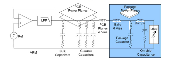
Fig. 1. A schematic diagram of a typical Power Distribution Network (PDN).
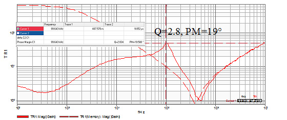
Fig. 2. This low frequency PDN impedance measurement shows that not all PDN impedance profiles are flat.
The mathematical evaluation of the voltage noise induced by a change in current can be easily accessed for a 2nd order distribution network using Laplace and/or Fourier techniques. This simple assessment quickly shows that there are a multitude of possible solutions depending on the nature of the current signal definition and whether the damping of the distribution network anti-resonance is critical, over-damped, or under-damped.
Relating Voltage and Current
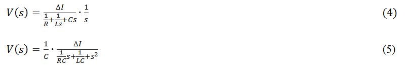
The Laplace solution of the parallel RLC circuit is easily evaluated as a function of the current through each of the R, L, and C elements.

Which can be rearranged to solve for the noise voltage, V:

In the case that the current signal is a unit step of magnitude ΔI, then the Laplace of the current signal is ΔI/s and the voltage can be written as:
In the under-damped case this results in the solution:
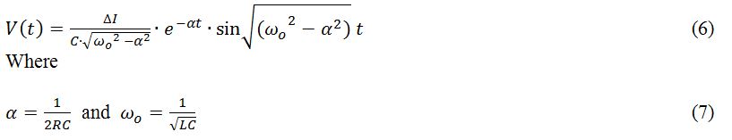
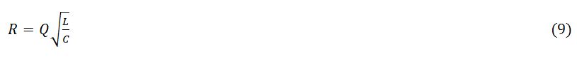
The Q of the parallel RLC circuit is defined as:

Solving for R results in:
Solving for α as a function of Q by substitution:

And finally, we can show that the exponential decay is related to the circuit Q:

Driving the circuit with a square wave rather than a sine wave results in an amplitude multiplication due to the Fourier coefficient 4/(nπ), causing a 27% larger fundamental amplitude than a sine wave. We have clearly shown that for the under-damped case of a single LCR circuit there are at least three solutions for a constant amplitude envelope, dependent on whether the current signal is a step, sine wave, or square. And so we have now shown that a single current step can result in three different voltages for a given impedance.
A SIMPLE LUMPED ELEMENT EXAMPLE
Using a second-order LCR network simulation model allows a visualization and comparison of the resulting solutions of these three cases. The circuit values are held constant in all three simulation cases. Constraining the current signal to a 0 to 2 Amp envelope allows a direct comparison of the step, sine, and square wave responses. The model schematic is shown in Fig. 3 and the resulting impedance and Q are shown in Fig. 4.
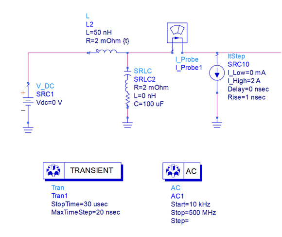
Fig. 3. A simple 2nd order LCR network constructed in Agilent ADS 2011.
The circuit Q can be calculated from the inductance, capacitance and series resistance as:

Fig. 4. The peak AC impedance simulation result of the 2nd order LCR network.
The Q can also be determined from the impedance -3dB and center frequencies. The AC simulation result shown in Fig. 4 indicates that the circuit peak impedance is 126 milliOhms with a Q of 5.56 as expected.
This circuit is then simulated using a 2A step, a 2App sine wave, and a 2App square wave current signal source for corroboration of the three expected voltage responses (see Figs. 5, 6, and 7, respectively). In each case, the plot shows both the excitation current and the resulting voltage signal. The sine wave is a pure source; therefore, we expect the time domain response to be equal to the peak impedance if the sine wave is at the exact frequency of the anti-resonance. At frequencies above or below the anti-resonant frequency, the resulting voltage will be smaller, though it will still be a direct reflection of the frequency-dependent network impedance.
Fig. 5 displays the results of applying the 2A step function, which results in a voltage excursion of 43mVpk. As expected, the voltage response is exponentially decaying due to the under-damped solution. This natural response is the smallest excursion of the three solutions.
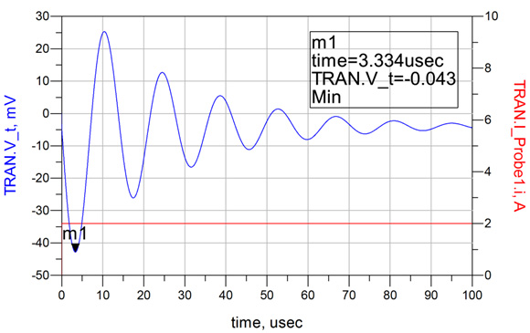
Fig 5. The response to a 0 to 2 Amp step results in a 43mVpk excursion and a damped ringing response as expected for this under-damped case, represented by a Q of 5.56.
In the second simulation the current signal is replaced with a sine wave at the anti-resonant frequency of 71.18 kHz, while maintaining the same envelope limits of 0 to 2A (see Fig. 6). This simulation results in a peak voltage excursion of 124mV, which is very close to what we expected based on a 1A peak excursion and a 126 milliOhm impedance. It is also noted that, as expected, the voltage response exhibits an exponential growth at a rate related to the circuit damping. The circuit requires approximately 6 cycles to reach the maximum steady state amplitude as a result of the resonant Q.
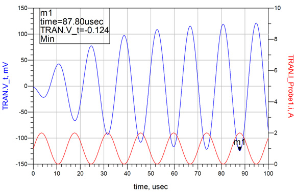
Fig. 6. The response to a 0 to 2Amp sine wave at the anti-resonant frequency results in a 124mVpk excursion and an exponential growth response as expected for this under-damped case, represented by a Q of 5.56. The steady state response for this condition is approximately a factor of 3 greater than the natural response case.
In the third simulation, the sine wave is replaced with a square wave of the same amplitude (see Fig. 7). The result is increased by a factor of 4/(nπ) as represented by the 158mV excursion for the same current envelope of 0 to 2A. The exponential growth is essentially the same as for the sine wave case, requiring 6 cycles to reach the steady state solution.
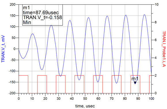
Fig. 7. The response to a 0 to 2Amp square wave at the anti-resonant frequency results in a 158mVpk excursion and an exponential growth response consistent with the sine wave case. The excursion is approximately 27% greater than the sine wave case, consistent with the 4/(nπ) Fourier coefficient multiplier.
To this point we shown mathematically, and confirmed through simulation, that there are three possible solutions for a given current amplitude. In this example, the signal ranges from 43mVpk to 158mVpk, for the same target impedance and depending only on the shape of the current signal. This is clearly a significant limitation of the target impedance assessment method.
Multiple Resonances Can Yield a Rogue Wave
Despite the goal of maintaining a flat impedance profile, a typical distribution network can have many resonances. Some are beyond control, while others are due to non-idealities of decoupling capacitor selection and placement, as well as PCB design tradeoffs.
A few additional elements are added to our simulation model in order to define two additional anti-resonances (see Figs. 8 and 9). These values are not selected based on any particular criteria, but are just spaced over a wide frequency range and adjusted to maintain an under-damped circuit and complying with a 125 milliOhm target impedance.
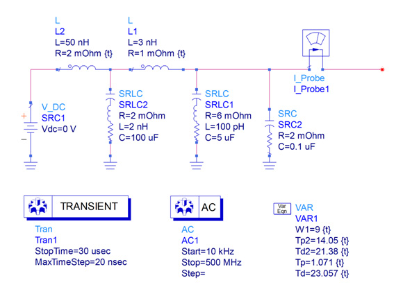
Fig. 8. The simple example circuit is modified to include two additional anti resonances.
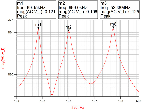
Fig. 9. An AC simulation of the modified example circuit confirms that each of the three anti-resonances is maintained at the desired target impedance of approximately 125 milliOhms.
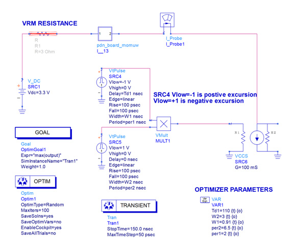
A load circuit is also constructed in order to allow versatility in the definition of the current signal, which is still maintained within an envelope of 0 to 2 Amps (see Fig. 10). The load circuit contains square current signals at each of the anti-resonant frequencies while also allowing adjustments of the time delays between each current signal application. SRC16 is used to provide the AC current for the impedance measurement. SRC12 is the lowest frequency, while SRC10, SRC11, CRC13, and SCR14 provide the burst for the second frequency and SRC14 provides the third and highest frequency.
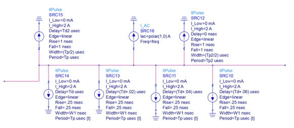
Fig. 10. A time domain load circuit allows application of current signals at any or all of the three anti-resonant frequencies as well as the adjustment of timing associated with the various current signals
The first current signal applied is from SRC12 at the first anti-resonant frequency of 69.15 kHz. The resulting voltage signal shows evidence of the two higher frequencies at the leading edge. At 21.38 uS, the second current signal is applied and the amplitude exponentially increases in accordance with the anti-resonant Q at the second frequency. At 23.057 uS, the third current signal is applied at the third anti-resonant frequency and the voltage excursion associated with this frequency also increases exponentially in accordance with the anti-resonant Q associated with this third frequency. These various signal characteristics are shown in the “zoom” windows in the following simulation plot. The timing for the application of the second and third signal applications is critical and there are three governing criteria.
- The current signals must be maintained within an envelope of 0 to 2 Amps.
- Each signal requires a minimum of cycles to reach steady-state amplitudes.
- The time shift between frequencies is critical, as each of the signal peaks must coincide in time despite the fact that these signals are not correlated or harmonically related.
Each of the three signal source amplitudes are defined as a square wave from 0 to 2 Amps and the timing is manually adjusted to assure that no two independent signals are positive at the same time; In order to keep the current excitation constant only one signal source can be positive at any instant in time.
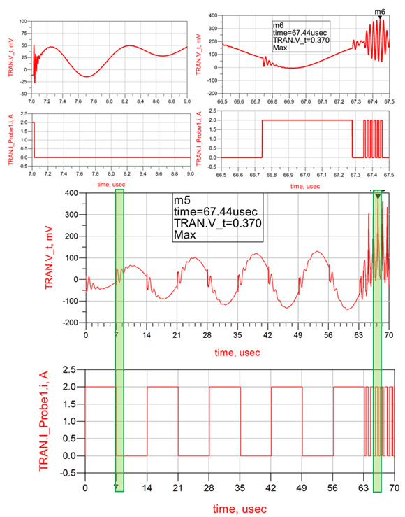
Fig. 11. The nominal simulation results showing the application of the first frequency, as well as, the addition of the other two frequencies. Two zoom views highlight the leading edge ring at the beginning of the simulation and a detailed look at the two additional frequencies.
Based on the simulator results and observations, the approximate PDN noise induced is not limited to the product of the change in current amplitude and the target impedance magnitude, but the product of the summation of the independent impedance peaks and current change products:

where 0 denotes the DC term.
USING THE ADS OPTIMIZER TO DETERMINE A SOLUTION
The Agilent ADS simulator includes many different performance optimizer algorithms and a “cockpit” from which the optimizers can be easily controlled. Each optimizer uses a different combination of error-function (EF) formulation and search methods to achieve a desired goal. In this study, the goal was defined as the maximum (or minimum) excursion resulting from the current signal. The optimizer is an ideal solution as there are many interrelated parameters and it would be very difficult to determine the correct result manually as there are many interdependent parameters.
The steps performed by the optimizer are:
- Perform a simulation using the nominal values for each parameter.
- Compare results with the goal (is it the maximum result) using the combination of error functions associated with the chosen optimizer.
- Modify the circuit parameters within the specified limits to obtain results that are likely to be closer to the goal. Each optimizer uses a different algorithm to find the best solution.
- Perform a new simulation with the modified circuit parameters. This process is repeated up to the maximum allowable number of iterations. If the optimizer does not improve the result for a number of simulations it will return the result without running the maximum number of iterations.
Before using the optimizer at least one goal component needs to be included in the schematic. The goal component establishes the measurement value for optimization and the desired final value for the measurement. The schematic must also include optimization limits for each parameter that can be adjusted and the limits within which that parameter may be adjusted. These limits can be set as absolute limits, percentage limits, or unrestrained limits. An optimizer type must be selected. The Random optimizer is selected and set to allow a maximum of 100 iterations, adjusting each element within the allowed range to achieve a maximum transient voltage excursion. The random optimizer works well when there are many interdependent parameters. The ADS simulation schematic showing the Optimizer functions is shown in Fig. 11.
While the Optimizer runs the simulator continually varies parameters in accordance with the chosen algorithm (random in this case). Graphic information, shown in Fig. 12 provides insight into which parameters have the most significant impact and how the output goal (voltage excursion in this case) is changing as parameters are being varied. This particular simulation was performed in less than 1 minute.
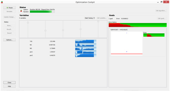
Fig. 12. The graphic Optimizer display, showing the optimizer progress and individual sensitivities. Note in this display the Optimizer variables are no longer changing, indicating that the optimum solution has been identified.
The results of the Optimizer are simulated and the voltage excursion is shown in Fig. 13. It is noted that due to the high Q of the first resonance it takes many cycles to reach maximum amplitude. Once the first resonance as reached maximum amplitude, at approximately 140ns the second current profile is introduced. The excursion from the second current profile is now stacked on top of the first resonance. In this case the resulting excursion is not the sum of the two individual excursions. This is due to the limitation imposed by the number of cycles at the second resonant frequency that can be included in the off time of the first resonance. If the two resonant frequencies were further separated, additional cycles could be included further increasing the voltage excursion. The current profile created by the Optimizer is shown in Fig. 14.
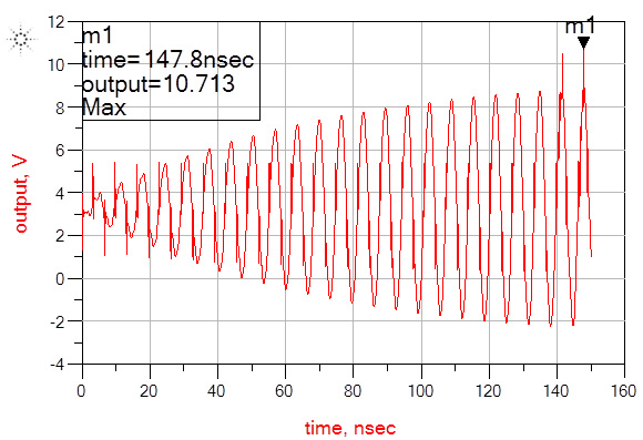
Fig. 13. The voltage excursion resulting from the current profile created by the Optimizer. Note that the second current profile is introduced at approximately 140ns.
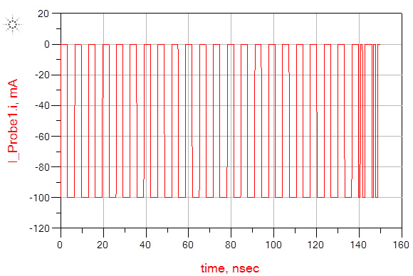
Fig. 14. The current profile created by the optimizer. The second profile is delayed approximately 140ns to allow the first resonance to reach maximum amplitude. The final result is limited by the maximum current step and by the limited number of cycles that fit in the off time of the first resonance.
While many publications calculate a maximum acceptable target impedance as the maximum allowable voltage excursion divided by the maximum expected current step, it is shown here that the target impedance assessment has a very weak relationship with the voltage excursion, even for a fixed current step. Several recent publications have introduced the concept of switching patterns and the impact that the switching pattern has on the result. This paper has shown that it is possible for the excursion to reach a maximum level that can be defined as an infinite summation of current impedance products for all harmonics including zero. A mathematical solution to the number of cycles required at each anti-resonance has also been determined in relation to the Q of the anti-resonance.
The optimal assessment method is still impedance; however, the assessment must carefully consider the conditions in which the anti-resonances become additive, as well as the general tendency for the majority of the noise signal to naturally gravitate to the higher frequencies due to the cumulative effect. It has also been shown that the effect of parameter tolerances can significantly impact the noise level and, again, the tolerances tend to skew the noise towards the higher frequencies, also due to the cumulative effect.
This paper was presented at DesignCon 2015.
Author Biography
Steve Sandler has been involved with power system engineering for more than 37 years. Steve is the founder of AEi Systems, a well-established leader in worst case circuit analysis and troubleshooting of satellite and other high reliability systems. He is also the founder of PICOTEST.com , a company specializing in accessories for high performance power system and distributed system testing. He frequently lectures and leads workshops internationally on the topics of power, PDN and distributed systems. Steve Sandler frequently writes articles and books related to power supply and PDN performance.
- Om P. Mandhana , “Modeling, analysis and design of resonant free power distribution network for modern microprocessor systems,” IEEE Trans. Advanced Packaging , vol. 27, no. 1, pp. 107-120, Feb. 2004.
- L. Besser and R. Gilmore, Practical Rf circuit design for modern wireless systems: Volume 1 passive circuits and systems , Norwood, MA: Artech Print on Demand, 2003.
- W. Cheng, A. Sarkar, S. Lin, and Z. Zheng, “Worst case switching pattern for core noise analysis,” DesignCon, 2009.
- S. Sun, L. D. Smith, and P. Boyle, “On-chip PDN noise characterization and modeling,” DesignCon, 2010.
- L. D. Smith, S. Sun, P. Boyle, and B. Krsnik, "System power distribution network theory and performance with various noise current stimuli including impacts on chip level timing,” in Proc. Custom Integrated Circuits Conference , San Jose, CA, 2009.
- I. Novak, “Comparison of power distribution network design methods: Bypass capacitor selection based on time domain and frequency domain performances”. Manuscript for TF-MP3 “Comparison of Power Distribution Network Design Methods” at DesignCon 2006, February 6-9, 2006, Santa Clara, CA
- C. K. Cheng “Power Distribution Network Simulation and Analysis” UCSD March, 4, 2010
- Hu, Xiang, Peng Du, and Chung-Kuan Cheng. "Exploring the rogue wave phenomenon in 3D power distribution networks." Electrical Performance of Electronic Packaging and Systems (EPEPS), 2010 IEEE 19th Conference on. IEEE, 2010.
Related Articles
Target impedance is not enough, measuring sub-milliohm pdn impedance, calibrating the 2-port probe for low impedance pdn measurements, report abusive comment.

- school Campus Bookshelves
- menu_book Bookshelves
- perm_media Learning Objects
- login Login
- how_to_reg Request Instructor Account
- hub Instructor Commons
- Download Page (PDF)
- Download Full Book (PDF)
- Periodic Table
- Physics Constants
- Scientific Calculator
- Reference & Cite
- Tools expand_more
- Readability
selected template will load here
This action is not available.
1.6: Voltage and Current in a Practical Circuit
- Last updated
- Save as PDF
- Page ID 681

- Tony R. Kuphaldt
- Schweitzer Engineering Laboratories via All About Circuits
Because it takes energy to force electrons to flow against the opposition of a resistance, there will be voltage manifested (or “dropped”) between any points in a circuit with resistance between them. It is important to note that although the amount of current (the quantity of electrons moving past a given point every second) is uniform in a simple circuit, the amount of voltage (potential energy per unit charge) between different sets of points in a single circuit may vary considerably:

Take this circuit as an example. If we label four points in this circuit with the numbers 1, 2, 3, and 4, we will find that the amount of current conducted through the wire between points 1 and 2 is exactly the same as the amount of current conducted through the lamp (between points 2 and 3). This same quantity of current passes through the wire between points 3 and 4, and through the battery (between points 1 and 4).
However, we will find the voltage appearing between any two of these points to be directly proportional to the resistance within the conductive path between those two points, given that the amount of current along any part of the circuit’s path is the same (which, for this simple circuit, it is). In a normal lamp circuit, the resistance of a lamp will be much greater than the resistance of the connecting wires, so we should expect to see a substantial amount of voltage between points 2 and 3, with very little between points 1 and 2, or between 3 and 4. The voltage between points 1 and 4, of course, will be the full amount of “force” offered by the battery, which will be only slightly greater than the voltage across the lamp (between points 2 and 3).
This, again, is analogous to the water reservoir system:

Between points 2 and 3, where the falling water is releasing energy at the water-wheel, there is a difference of pressure between the two points, reflecting the opposition to the flow of water through the water-wheel. From point 1 to point 2, or from point 3 to point 4, where water is flowing freely through reservoirs with little opposition, there is little or no difference of pressure (no potential energy). However, the rate of water flow in this continuous system is the same everywhere (assuming the water levels in both pond and reservoir are unchanging): through the pump, through the water-wheel, and through all the pipes. So it is with simple electric circuits: the rate of electron flow is the same at every point in the circuit, although voltages may differ between different sets of points.
- More from M-W
- To save this word, you'll need to log in. Log In
Definition of excursion
Did you know.
In Latin, the prefix ex- means "out of" and the verb currere means "to run." When the two are put together, they form the verb excurrere , literally "to run out" or "to extend." Excurrere gave rise not only to excursion but also to excurrent (an adjective for things having channels or currents that run outward) and excursus (meaning "an appendix or digression that contains further exposition of some point or topic"). Other words deriving from currere include corridor , curriculum , and among newer words, parkour .
Examples of excursion in a Sentence
These examples are programmatically compiled from various online sources to illustrate current usage of the word 'excursion.' Any opinions expressed in the examples do not represent those of Merriam-Webster or its editors. Send us feedback about these examples.
Word History
Latin excursion-, excursio , from excurrere
circa 1587, in the meaning defined at sense 1a
Theme music by Joshua Stamper ©2006 New Jerusalem Music/ASCAP
Get Word of the Day delivered to your inbox!
Dictionary Entries Near excursion
excursional
Cite this Entry
“Excursion.” Merriam-Webster.com Dictionary , Merriam-Webster, https://www.merriam-webster.com/dictionary/excursion. Accessed 21 Apr. 2024.
Kids Definition
Kids definition of excursion.
from Latin excursio, excursion- "a going out," from excurrere "to run out, make an excursion, extend," from ex- "out, forth" and currere "to run" — related to current
Medical Definition
Medical definition of excursion, more from merriam-webster on excursion.
Nglish: Translation of excursion for Spanish Speakers
Britannica English: Translation of excursion for Arabic Speakers
Subscribe to America's largest dictionary and get thousands more definitions and advanced search—ad free!

Can you solve 4 words at once?
Word of the day, noblesse oblige.
See Definitions and Examples »
Get Word of the Day daily email!
Popular in Grammar & Usage
Your vs. you're: how to use them correctly, every letter is silent, sometimes: a-z list of examples, more commonly mispronounced words, how to use em dashes (—), en dashes (–) , and hyphens (-), absent letters that are heard anyway, popular in wordplay, the words of the week - apr. 19, 10 words from taylor swift songs (merriam's version), a great big list of bread words, 10 scrabble words without any vowels, 12 more bird names that sound like insults (and sometimes are), games & quizzes.

Frequency excursions in complex power systems — A modular approach
Ieee account.
- Change Username/Password
- Update Address
Purchase Details
- Payment Options
- Order History
- View Purchased Documents
Profile Information
- Communications Preferences
- Profession and Education
- Technical Interests
- US & Canada: +1 800 678 4333
- Worldwide: +1 732 981 0060
- Contact & Support
- About IEEE Xplore
- Accessibility
- Terms of Use
- Nondiscrimination Policy
- Privacy & Opting Out of Cookies
A not-for-profit organization, IEEE is the world's largest technical professional organization dedicated to advancing technology for the benefit of humanity. © Copyright 2024 IEEE - All rights reserved. Use of this web site signifies your agreement to the terms and conditions.
- LiveWire Homepage
- NERC Training LMS

- Active Standards
- BAL-001-2 – Real Power Balancing Control Performance
- BAL-001-TRE-1: Primary Frequency Response in the ERCOT Region
- BAL-001-TRE-2 – Primary Frequency Response in the ERCOT Region
- BAL-002-3: Disturbance Control Standard – Contingency Reserve for Recovery from a Balancing Contingency Even
- BAL-002-WECC-2a — Contingency Reserve
- BAL-003-1.1 – Frequency Response and Frequency Bias Setting
- BAL-003-2 – Frequency Response and Frequency Bias Setting
- BAL-004-WECC-3: Automatic Time Error Correction
- BAL-005-1: Balancing Authority Control
- BAL-502-RF-03: Planning Resource Adequacy Analysis, Assessment and Documentation
- CIP-002-5.1a – Cyber Security – BES Cyber System Categorization
- CIP-003-6 – Cyber Security – Security Management Controls
- CIP-003-8 – Cyber Security — Security Management Controls
- CIP-004-6 – Cyber Security – Personnel & Training
- CIP-005-5 – Cyber Security — Electronic Security Perimeter(s)
- CIP-005-6 — Cyber Security – Electronic Security Perimeter(s)
- CIP-006-6 – Cyber Security – Physical Security of BES Cyber Systems
- CIP-007-6 – Cyber Security – System Security Management
- CIP-008-5 – Cyber Security – Incident Reporting and Response Planning
- CIP-008-6 — Cyber Security — Incident Reporting and Response Planning
- COM-001-3 – Communications
- COM-002-4 – Operating Personnel Communications Protocols
- EOP-004-4 – Event Reporting
- EOP-005-3: System Restoration from Blackstart Resources
- EOP-006-3: System Restoration Coordination
- EOP-008-2: Loss of Control Center Functionality
- EOP-010-1 – Geomagnetic Disturbance Operations
- EOP-011-1 – Emergency Operations
- FAC-001-3 – Facility Interconnection Requirements
- FAC-002-2 – Facility Interconnection Studies
- FAC-002-3 – Facility Interconnection Studies
- FAC-002-3 — Facility Interconnection Studies
- FAC-003-4 – Transmission Vegetation Management
- FAC-008-3: Facility Ratings
- FAC-010-3 – System Operating Limits Methodology for the Planning Horizon
- FAC-011-3 – System Operating Limits Methodology for the Operations Horizon
- FAC-013-2: Assessment of Transfer Capability for the Near-term Transmission Planning Horizon
- FAC-014-2: Establish and Communicate System Operating Limits
- INT-001-3: Interchange Information
- INT-003-3: Interchange Transaction Implementation
- INT-004-2: Dynamic Interchange Transaction Modifications
- INT-004-3.1: Dynamic Transfers
- INT-005-3: Interchange Authority Distributes Arranged Interchange
- INT-006-3: Response to Interchange Authority
- INT-006-4: Evaluation of Interchange Transactions
- INT-006-5 – Evaluation of Interchange Transactions
- INT-007-1: Interchange Confirmation
- IRO-001-4: Reliability Coordination – Responsibilities
- IRO-002-6 – Reliability Coordination – Monitoring and Analysis
- IRO-006-5: Reliability Coordination — Transmission Loading Relief
- IRO-006-EAST-2: Transmission Loading Relief Procedure for the Eastern Interconnection
- IRO-006-WECC-2: Qualified Transfer Path Unscheduled Flow (USF) Relief
- IRO-006-WECC-3: Qualified Path Unscheduled Flow (USF) Relief
- IRO-008-2 – Reliability Coordinator Operational Analyses and Real-time Assessments
- IRO-009-2 – Reliability Coordinator Actions to Operate Within IROLs
- IRO-010-2 – Reliability Coordinator Data Specification and Collection
- IRO-010-3 — Reliability Coordinator Data Specification and Collection
- MOD-001-1a: Available Transmission System Capability
- MOD-004-1: Capacity Benefit Margin
- MOD-008-1: TRM Calculation Methodology
- MOD-020-0: Providing Interruptible Demands and DCLM Data
- MOD-025-2: Verification and Data Reporting of Generator Real and Reactive Power Capability and Synchronous Condenser Reactive Power Capability
- MOD-026-1: Verification of Models and Data for Generator Excitation Control System or Plant Volt/Var Control Functions
- MOD-027-1: Verification of Models and Data for Turbine/Governor and Load Control or Active Power/Frequency Control Functions
- MOD-028-2: Area Interchange Methodology
- MOD-029-2a: Rated System Path Methodology
- MOD-030-3: Flowgate Methodology
- NUC-001-3 – Nuclear Plant Interface Coordination
- NUC-001-4— Nuclear Plant Interface Coordination
- PER-003-2: Operating Personnel Credentials
- PER-005-2: Operations Personnel Training
- PER-006-1 – Specific Training for Personnel
- PRC-001-1.1 (ii): System Protection Coordination
- PRC-002-2: Disturbance Monitoring and Reporting Requirements
- PRC-004-5(i): Protection System Misoperation Identification and Correction
- PRC-004-WECC-2: Protection System and Remedial Action Scheme Misoperation
- PRC-005-1.1b: Transmission and Generation Protection System Maintenance and Testing
- PRC-005-6: Protection System, Automatic Reclosing, and Sudden Pressure Relaying Maintenance
- PRC-006-3: Automatic Underfrequency Load Shedding
- PRC-006-5 — Automatic Underfrequency Load Shedding
- PRC-006-NPCC-1: Automatic Underfrequency Load Shedding
- PRC-006-NPCC-2 – Automatic Underfrequency Load Shedding
- TOP-001-4: Transmission Operations
- TOP-002-4: Operations Planning
- TOP-003-3: Operational Reliability Data
- TOP-003-4 — Operational Reliability Data
- TOP-010-1(i): Real-time Reliability Monitoring and Analysis Capabilities
- TOP‐001‐5 ‐ Transmission Operations
- TPL-001-4: Transmission System Planning Performance Requirements
- TPL-007-4 – Transmission System Planned Performance for Geomagnetic Disturbance Events
- VAR-001-5: Voltage and Reactive Control
- VAR-002-4.1: Generator Operation for Maintaining Network Voltage Schedules
- VAR-501-WECC-3.1: Power System Stabilizer (PSS)
PRC-010-2: Undervoltage Load Shedding
To establish an integrated and coordinated approach to the design, evaluation, and reliable operation of Undervoltage Load Shedding Programs (UVLS Programs).
Applicability
4.1. Functional Entities
4.1.1 Planning Coordinator .
4.1.2 Transmission Planner .
4.1.3 Undervoltage load shedding (UVLS) entities – Distribution Providers and Transmission Owners responsible for the ownership, operation, or control of UVLS equipment as required by the UVLS Program established by the Transmission Planner or Planning Coordinator
Effective Date
See Project 2008-02.2 Implementation Plan.
Requirements and Measures
R1. Each Planning Coordinator or Transmission Planner that is developing a UVLS Program shall evaluate its effectiveness and subsequently provide the UVLS Program ’s specifications and implementation schedule to the UVLS entities responsible for implementing the UVLS Program . The evaluation shall include, but is not limited to, studies and analyses that show: [Violation Risk Factor: High] [Time Horizon: Long-term Planning]
1.1. The implementation of the UVLS Program resolves the identified undervoltage issues that led to its development and design.
1.2. The UVLS Program is integrated through coordination with generator voltage ride-through capabilities and other protection and control systems, including, but not limited to, transmission line protection, autoreclosing, Remedial Action Schemes, and other undervoltage-based load shedding programs.
M1. Acceptable evidence may include, but is not limited to, date-stamped studies and analyses, reports, or other documentation detailing the effectiveness of the UVLS Program , and date-stamped communications showing that the UVLS Program specifications and implementation schedule were provided to UVLS entities.
R2. Each UVLS entity shall adhere to the UVLS Program specifications and implementation schedule determined by its Planning Coordinator or Transmission Planner associated with UVLS Program development per Requirement R1 or with any Corrective Action Plans per Requirement R5. [Violation Risk Factor: High] [Time Horizon: Long-term Planning]
M2. Acceptable evidence must include date-stamped documentation on the completion of actions and may include, but is not limited to, identifying the equipment armed with UVLS relays, the UVLS relay settings, associated Load summaries, work management program records, work orders, and maintenance records.
R3. Each Planning Coordinator or Transmission Planner shall perform a comprehensive assessment to evaluate the effectiveness of each of its UVLS Programs at least once every 60 calendar months. Each assessment shall include, but is not limited to, studies and analyses that evaluate whether: [Violation Risk Factor: Medium] [Time Horizon: Long-term Planning]
3.1. The UVLS Program resolves the identified undervoltage issues for which the UVLS Program is designed
3.2. The UVLS Program is integrated through coordination with generator voltage ride-through capabilities and other protection and control systems, including, but not limited to, transmission line protection, autoreclosing, Remedial Action Schemes, and other undervoltage-based load shedding programs.
M3 . Acceptable evidence may include, but is not limited to, date-stamped reports or other documentation detailing the assessment of the UVLS Program .
R4 . Each Planning Coordinator or Transmission Planner shall, within 12 calendar months of an event that resulted in a voltage excursion for which its UVLS Program was designed to operate, perform an assessment to evaluate: [Violation Risk Factor: Medium] [Time Horizon: Operations Planning]
4.1. Whether its UVLS Program resolved the undervoltage issues associated with the event, and
4.2. The performance (i.e., operation and non-operation) of the UVLS Program equipment.
M4. Acceptable evidence may include, but is not limited to, date-stamped event data, event analysis reports, or other documentation detailing the assessment of the UVLS Program and associated equipment.
R5. Each Planning Coordinator or Transmission Planner that identifies deficiencies during an assessment performed in either Requirement R3 or R4 shall develop a Corrective Action Plan to address the deficiencies and subsequently provide the Corrective Action Plan , including an implementation schedule, to UVLS entities within three calendar months of completing the assessment. [Violation Risk Factor: Medium] [Time Horizon: Operations Planning]
M5. Acceptable evidence must include a date-stamped Corrective Action Plan that addresses identified deficiencies and may also include date-stamped reports or other documentation supporting the Corrective Action Plan . Evidence should also include date-stamped communications showing that the Corrective Action Plan and an associated implementation schedule were provided to UVLS entities.
R6. Each Planning Coordinator that has a UVLS Program in its area shall update a database containing data necessary to model the UVLS Program (s) in its area for use in event analyses and assessments of the UVLS Program at least once each calendar year. [Violation Risk Factor: Lower] [Time Horizon: Operations Planning]
M6. Acceptable evidence may include, but is not limited to, date-stamped spreadsheets, database reports, or other documentation demonstrating a UVLS Program database was updated.
R7 . Each UVLS entity shall provide data to its Planning Coordinator according to the format and schedule specified by the Planning Coordinator to support maintenance of a UVLS Program database. [Violation Risk Factor: Lower] [Time Horizon: Operations Planning]
M7. Acceptable evidence may include, but is not limited to, date-stamped emails, letters, or other documentation demonstrating data was provided to the Planning Coordinator as specified.
R8. Each Planning Coordinator that has a UVLS Program in its area shall provide its UVLS Program database to other Planning Coordinators and Transmission Planners within its Interconnection , and other functional entities with a reliability need, within 30 calendar days of a written request. [Violation Risk Factor: Lower] [Time Horizon: Operations Planning]
M8. Acceptable evidence may include, but is not limited to, date-stamped emails, letters, or other documentation demonstrating that the UVLS Program database was provided within 30 calendar days of receipt of a written request.
1. Compliance Monitoring Process
1.1. Compliance Enforcement Authority
As defined in the NERC Rules of Procedure, “Compliance Enforcement Authority” means NERC or the Regional Entity in their respective roles of monitoring and enforcing compliance with the NERC Reliability Standards.
1.2. Evidence Retention
The following evidence retention periods identify the period of time an entity is required to retain specific evidence to demonstrate compliance. For instances where the evidence retention period specified below is shorter than the time since the last audit, the Compliance Enforcement Authority may ask an entity to provide other evidence to show that it was compliant for the full-time period since the last audit.
The Planning Coordinator , Transmission Planner , Distribution Provider , and Transmission Owner shall keep data or evidence to show compliance as identified below unless directed by its Compliance Enforcement Authority to retain specific evidence for a longer period of time as part of an investigation.
The applicable entity shall retain documentation as evidence for six calendar years.
If an applicable entity is found non-compliant, it shall keep information related to the non-compliance until mitigation is complete and approved, or for the time specified above, whichever is longer.
The Compliance Enforcement Authority shall keep the last audit records and all requested and submitted subsequent audit records.
1.3. Compliance Monitoring and Assessment Processes
“Compliance Monitoring and Assessment Processes” refers to the identification of the processes that will be used to evaluate data or information for the purpose of assessing performance or outcomes with the associated reliability standard.
1.4. Additional Compliance Information
Guidelines and Technical Basis
Introduction.
The standard drafting team provides the following discussion to support the approach to the standard. The information is meant to enhance the understanding of the reliability needs and deliverable expectations of each requirement, supported as necessary by technical principles and industry experience.
Guidelines for UVLS Program Definition
The definition for the term, “ Undervoltage Load Shedding Program ” or “ UVLS Program ” includes automatic load shedding programs that utilize only voltage inputs at locations where action is taken to shed load. As such, the failure of a single component is unlikely to affect the reliable operation of the program.
The UVLS Program definition excludes centrally controlled undervoltage-based load shedding, which utilizes inputs from multiple locations and may also utilize inputs other than voltages (such as generator reactive reserves, facility loadings, equipment statuses, etc.). The design and characteristics of a centrally controlled undervoltage-based load shedding system are the same as that of a Remedial Action Scheme ( RAS ), wherein load shedding is the remedial action. Therefore, just like for a RAS , the failure of a single component can compromise the reliable operation of centrally controlled undervoltage-based load shedding.
To ensure that the applicability of the standard includes only those undervoltage-based load shedding systems whose performance has an impact on system reliability, a UVLS Program must mitigate risk of one or more of the following: voltage instability, voltage collapse, or Cascading impacting the Bulk Electric System ( BES ). An example of a program that would not fall under this category is undervoltage-based load shedding installed to mitigate damage to equipment or local loads that are directly affected by the low voltage event.
Figure 1 below is an example of a BES subsystem for which a UVLS system could be used as a solution to mitigate various issues following the loss of the 345 kV double circuit line between buses A and B. If the consequence of this Contingency does not impact the BES by leading to voltage instability, voltage collapse, or Cascading , a UVLS system (installed at either, or both, bus B and D) used to mitigate this Contingency would not fall under the definition of a UVLS Program . However, if this same UVLS system is used to mitigate an Adverse Reliability Impact outside this contained area, it would be classified as a wide-area undervoltage problem and would fall under the definition of UVLS Program .
Guidelines for Requirements
Table 1 provides a high-level overview of the requirements contained in the standard.

Guidelines for Requirement R1
A UVLS Program may be developed and implemented to either serve as a safety net system protection measure against unforeseen extreme Contingencies or to achieve specific system performance for known transmission Contingencies for which dropping of load is allowed under Transmission Planning (TPL) Reliability Standards. Regardless of the purpose, it is important that the UVLS Program being implemented is effective in terms that it mitigates undervoltage conditions impacting the Bulk Electric System ( BES ), leading to voltage instability, voltage collapse, or Cascading . Consideration should be given to voltage set points and time delays, rate of voltage decay or recovery, power flow levels, etc. when designing a UVLS Program .
For the UVLS Program to be effective in achieving its goal, it is also necessary that the UVLS Program is coordinated with generator voltage ride-through capabilities and other protection and control systems that may have an impact on the performance of the UVLS Program . Some of these protection and control systems may include, but are not limited to, transmission line protection, RAS , other undervoltage-based load shedding programs, autoreclosing, and controls of shunt capacitors, reactors, and static voltampere-reactive systems (SVSs).
For example, if the purpose of a UVLS Program is to mitigate fault-induced delayed voltage recovery (FIDVR) events in a large load center that also includes local generation, it is important that such a UVLS Program is coordinated with local generators’ voltage ride-through capabilities. Generators in the vicinity of a load center are critical to providing dynamic voltage support to the system during FIDVR events. To maximize the benefit of on-line generation, the best practice may be to shed load prior to generation trip. However, occasionally, it may be best to let generation trip prior to load shed. Therefore, the impact of generation tripping should be considered while designing a UVLS Program .
Another example that can be highlighted is the coordination of a UVLS Program with automatic shunt reactor tripping devices if there are any on the system. Most likely, any shunt reactors on the system will trip off automatically after some time delay during low voltage conditions. In such cases, shunt reactors should be tripped before the load is shed to preserve the system. This may require coordination of time delays associated with the UVLS Program with shunt reactor tripping devices.
The examples given above demonstrate that, for a UVLS Program to be effective, proper consideration should be given to coordination of a UVLS Program with generator ride-through capabilities and other protection and control systems.
Guidelines for Requirement R2
Once a Planning Coordinator ( PC ) or Transmission Planner (TP) has identified a need for a UVLS Program , the Planning Coordinator or Transmission Planner will develop a program that includes specifications and an implementation schedule, which are then provided to UVLS entities per Requirement R1. Specifications may include voltage set points, time delays, amount of load to be shed, and the location at which load needs to be shed. If UVLS entities do not implement the UVLS Program according to the specifications and schedule provided, the UVLS Program may not be effective and may not achieve its intended goal. The UVLS entity must document that all necessary actions were completed to implement the UVLS Program .
Similarly, when a Corrective Action Plan (CAP) to address UVLS Program deficiencies is developed by the Planning Coordinator or Transmission Planner and provided to UVLS entities per Requirement R5, UVLS entities must comply with the CAP and its associated implementation schedule to ensure that the UVLS Program is effective. The UVLS entity is required to complete the actions specified in the CAP, document the plan implementation, and retain the appropriate evidence to demonstrate implementation and completion.
Deferrals or other relevant changes to the UVLS Program specifications or CAP need to be documented so that the record includes not only what was planned, but what was implemented. Depending on the planning and documentation format used by the responsible entity, evidence of a successful execution could consist of signed-off work orders, printouts from work management systems, spreadsheets of planned versus completed work, timesheets, work inspection reports, paid invoices, photographs, walk-through reports, or other evidence.
For example, documentation of a CAP provides an auditable progress and completion confirmation for the identified UVLS Program deficiency:
CAP Example 1 – Corrective actions for a quick triggering problem; preemptive actions for similar installations:
The PC or TP obtains fault records from a UVLS entity that participates in its UVLS Program that indicate a group of UVLS relays triggered at the appropriate undervoltage level but with shorter delays than expected. The PC or TP directed the UVLS entity to schedule onsite inspections within three weeks. The results of the inspection confirmed that the delay-time programmed on the relays was 60 cycles instead of 90 cycles. The PC or TP then directed the UVLS entity to correct to a 90-cycle time delay setting of the UVLS relays identified to have shorter time delay settings within eight weeks.
Applicability to other UVLS relays: The PC or TP then developed a schedule with the UVLS entity to verify and adjust all remaining UVLS relays time delay settings within a one-year period.
The PC or TP verified completion of verification and adjustment of the time delay settings for all of the UVLS entity’s equipment that participates in the PC or TP UVLS Program
CAP Example 2 – Corrective actions for a firmware problem; preemptive actions for similar installations:
The PC or TP obtains fault records on 6/4/2014 from a UVLS entity that participates in its UVLS Program . The UVLS entity also provided the fault records to the manufacturer, who responded on 6/11/2014 that the Misoperation 1 of the UVLS relay was caused by a bug in version 2 firmware, and recommended installing version 3 firmware. The PC or TP approved the UVLS entity’s plan to schedule Version 3 firmware installation on 6/12/2014.
Applicability to other UVLS relays: The PC or TP then developed a schedule with the UVLS entity to install firmware version 3 at all of the UVLS entity’s UVLS relays that are determined to be programmed with version 2 firmware. The completion date was scheduled no-later-than 12/31/2014.
The firmware replacements were completed on 12/4/2014.
Guidelines for Requirement R3
In addition to the initial studies required to develop a UVLS Program , periodic comprehensive assessments (detailed analyses) are required to ensure its continued effectiveness. This assessment is required to be completed at least once every 60 calendar months to capture the accumulated effects of minor changes to the system that have occurred since the last assessment was completed. However, at any point in time, a Planning Coordinator or Transmission Planner may also determine that a material change 2 to system topology or operating conditions affects the performance of the UVLS Program and therefore necessitates the same comprehensive assessment. Regardless of the trigger, each assessment should include an evaluation of each UVLS Program to ensure the continued integration through coordination.
This comprehensive assessment complements the TPL-001-4 annual assessment requirement to evaluate the impact of protection systems. The 60-month period is the same time frame used in TPL-001-4 and in PRC-006-1.
As specified in Requirement R3, a comprehensive assessment must be performed at least once every 60 calendar months. If a Planning Coordinator or Transmission Planner conducts a comprehensive assessment sooner for the reasons discussed above, the 60-month time period would restart upon completion of this assessment.
Guidelines for Requirement R4
After a voltage excursion event, the goal of the assessment required in Requirement R4 is to evaluate: (1) whether the UVLS Program resolved the undervoltage issues, and (2) the performance of the UVLS Program equipment. The assessment should include event data analysis, such as the relevant sequence of events leading to the undervoltage conditions (e.g., Contingencies, operation of protection systems, and RAS ) and field measurements useful to analyzing the behavior of the system. A comprehensive description of the UVLS Program operation should be presented, including conditions of the trigger (e.g., voltage levels, time delays) and amount of load shed for each affected substation. Assessment of the event is performed to evaluate the level of performance of the program for the event of interest and to identify deficiencies to be included in a CAP per Requirement R5. Misoperation of UVLS equipment is addressed as a deficiency. Reporting of UVLS equipment Misoperations are addressed by the NERC Request for Data and Information, Protection System Misoperation Data Collection . 3
The studies and analyses showing the effectiveness of the UVLS Program can be similar to what is required in Requirements R1 and R3, but should include a clear link between the evaluation of effectiveness (in studies using simulations) and the analysis of the event (with measurements and event data) that actually occurred. For example, differences between the expected and actual system behavior for the event of interest should be discussed and modeling assumptions should be evaluated. Important discrepancies between the simulations and the actual event should be investigated.
Considering the importance of an event that involves the operation of a UVLS Program , the 12- calendar-month period provides adequate time to analyze the event and perform an assessment while identifying deficiencies within a reasonable time. This time period is also required in PRC- 006-1.
Guidelines for Requirement R5
Requirement R5 promotes the prudent correction of an identified problem during the assessment of a UVLS Program . Per Requirements R3 and R4, an assessment of an active UVLS Program is triggered:
- Within 12 calendar months of an event that resulted in a voltage excursion for whichthe program was designed to operate
- At least once every 60 calendar months. The default time frame of 60 calendar monthsor less between assessments has the intention to assure that the cumulative changes tothe network and operating condition affecting the UVLS Program are evaluated
Since every UVLS is unique, if material changes are made to system topology or operating conditions, the Planning Coordinator or Transmission Planner will decide the degree to which the change in topology or operating condition becomes a material change sufficient to trigger an assessment of the existing UVLS Program .
A CAP is a list of actions and an associated timetable for implementation to remedy a specific problem. It is a proven tool for resolving operational problems. Per Requirement R5, the Planning Coordinator or Transmission Planner is required to develop a CAP and provide it to UVLS entities to accomplish the purpose of this requirement, which is to prevent future deficiencies in the UVLS Program , thereby minimizing risk to the system. Determining the cause of the deficiency is essential in developing an effective CAP to avoid future re-occurrence of the same problem. A CAP can be revised if additional causes are found.
Based on industry experience and operational coordination timeframes, three calendar months from the date an assessment is completed is a reasonable time frame for development of a CAP, including time to consider alternative solutions and coordination of resources. The “within three calendar months” time frame is solely to develop a CAP, including its implementation schedule, and provide it to UVLS entities. It does not include the time needed for its implementation by UVLS entities. This implementation time frame is dictated within the CAP’s associated timetable for implementation, and the execution of the CAP according to its schedule is required in Requirement R2.
Guidelines for Requirements R6–R8
An accurate UVLS Program database is necessary for the Planning Coordinator or Transmission Planner to perform system reliability assessment studies and event analysis studies. Without accurate data, there is a possibility that annual reliability assessment studies that are performed by the Planning Coordinator or Transmission Planner can lead to erroneous results and therefore impact reliability. Also, without the accurate data, it is very difficult for the Planning Coordinator or Transmission Planner to duplicate a UVLS event and determine the root cause of the problem.
To support a UVLS Program database, it is necessary for each UVLS entity to provide accurate data to its Planning Coordinator . Each UVLS entity will provide the data according to the specified format and schedule provided by the Planning Coordinator . This is required in order for the Planning Coordinator to maintain and support a comprehensive UVLS Program database. By having a comprehensive database, the Planning Coordinator can embark on a reliability assessment or event analysis/benchmarking studies, identify the issues with the UVLS Program , and develop Corrective Action Plans.
The UVLS Program database may include, but is not limited to the following:
- Owner and operator of the UVLS Program
- Size and location of customer load, or percent of connected load, to be interrupted
- Corresponding voltage set points and clearing times
- Time delay from initiation to trip signal
- Breaker operating times
- Any other schemes that are part of or impact the UVLS Programs, such as related generation protection, islanding schemes, automatic load restoration schemes, underfrequency load shedding (UFLS), and RAS
Additionally, the UVLS Program database is required to be updated annually (once every calendar year) by the Planning Coordinator . The intent here is for UVLS entities to review the data annually and provide changes to the Planning Coordinators so that Planning Coordinators can keep the databases current and accurate for performing event analysis and other assessments.
Finally, a Planning Coordinator is required to provide information to other Planning Coordinators and Transmission Planners within its Interconnection , and other functional entities with a reliability need, within 30 calendar days of receipt of a written request. Thirty calendar days was selected as the time frame as it is considered to be reasonable and well- accepted by the industry. Also, this requirement of sharing the database with applicable functional entities supports the directive provided by FERC that requires an integrated and coordinated approach to UVLS programs (Paragraph 1509 of FERC Order No. 693).
Frequently Asked Questions
To succinctly address common comment themes that require drafting team response on Project 2008-02 UVLS (proposed PRC-010-1), the drafting team provides the following discussion in the construct of an FAQ format.
This Frequently Asked Questions (FAQ) document was created during the development of PRC010-1 (Undervoltage Load Shedding) 4 , 5 to succinctly address common comment themes with respect to the approach and intent of the Project 2008-02 Undervoltage Load Shedding (UVLS) 6 standard drafting team (“drafting team”). This FAQ document is the outcome of comments received during comment periods and multiple outreach sessions with industry. All comments submitted by industry during comment periods may be reviewed on the project page.
Subsequent to the adoption of PRC-010-1, the UVLS drafting team made minor revisions to the standard address the UVLS Misoperation identification and correction. 7 This FAQ document was amended to reflect up the approach and intent of the drafting team during the development of PRC-010-2 concerning Misoperation of UVLS equipment.
Purpose of Standard Revision
1) What is the basis for a revision of the existing UVLS standards?
The initial input into a revision of the existing UVLS standards is FERC Order No. 693, 8 Paragraph 1509, which directed the ERO to develop a modification of PRC-010-0 that “requires that an integrated and coordinated approach be included in all protection systems on the Bulk-Power System , including generators and transmission lines, generators’ low voltage ride through capabilities, and UFLS and UVLS programs.” In addition, The Final Report on the August 14, 2003 Blackout in the United States and Canada: Causes and Recommendations 9 (“August 14 Blackout Report”) showed that proper coordination would have mitigated effects if UVLS was used as a tool.
Additional inputs included 1) recommendations from the NERC System Protection and Control Subcommittee (SPCS) in its December 2010 Technical Review of UVLS-Related Standards 10 to combine the four existing UVLS standards, revise the applicability to entities responsible for UVLS program design, implementation, and coordination, specifically include a requirement for assessment of coordination between UVLS programs and all other protection systems, and differentiate post-event validation of UVLS program design from verifying correct operation of UVLS equipment; 2) the existing UVLS standards were not in the current results-based format; 3) the preceding revision of the underfrequency load shedding (UFLS) standards had similar types of requirements and had been completed under the construct of a consolidation; and 4) the Independent Expert Review Panel recommendations, which included an evaluation of the existing standards’ applicability and level of specificity. 10
The drafting team agrees that a lack of coordination among protection systems is a key risk to reliability. As part of the revision to address this, the drafting team also agreed that an evaluation and consolidation of the existing UVLS standards was necessary to meet current Reliability Standard development initiatives and to provide clear, comprehensive requirements to address the application and coordination of UVLS.
2) UVLS programs are not mandatory—is compliance for an optional tool necessary?
The drafting team asserts that a key takeaway from the August 14 Blackout Report is that coordination of UVLS with other protection systems could have mitigated the effects if UVLS was used as a tool. Although the use of UVLS is not mandatory, if it is determined that this system preservation measure is necessary to support reliability and a UVLS program is installed, the program needs to be properly coordinated, implemented, and assessed due to the inherent associated reliability risks. As such, there needs to be a level of performance required to properly protect system reliability. Of note, PRC-010-1 and PRC-010-2 apply to the defined term “ UVLS Program ,” which limits the standard’s applicability to only those undervoltage-based load shedding programs whose performance has an impact on system reliability. 11
Coordination with Project 2009-03 Emergency Operations
3) EOP-003-2 has potential redundant requirements with proposed PRC-010-1—how is this being addressed?
As part of its five-year review, Project 2009-03 – Emergency Operations (EOP) identified EOP003-2 ( Load Shedding Plans), 12 Requirements R2, R4, and R7 as being more properly covered by Project 2008-02 – UVLS. Both projects were strategically coordinated to move in lockstep from a timing perspective to address these requirements. Project 2009-03 – EOP proposed to revise and consolidate EOP-001-2.1b ( Emergency Operations Planning ), 13 EOP-002-3 (Capacity and Energy Emergencies), 14 and EOP-003-2 to create EOP-011-1, will retire the noted EOP-003-2 requirements (among other revisions), and the Project 2008-02 – UVLS Mapping Document will show how PRC-010-1 encompasses the retired content accordingly. Slated to have aligning effective dates, both EOP-011-1 (Emergency Operations) 15 and PRC-010-1 will be posted and balloted separately but concurrently, so that industry stakeholders will be able to clearly evaluate the transition. Please see the posted Project 2008-02 UVLS Project Coordination Plan for more information.
“UVLS Program” Definition
4) Why is the introduction of the new defined term “ UVLS Program ” necessary?
The drafting team found it necessary to introduce the term “ UVLS Program ” for inclusion in the Glossary of Terms Used in NERC Reliability Standards 16 (“NERC Glossary”) because different types of UVLS systems need to be treated appropriately with respect to reliability requirements. Therefore, the term establishes which UVLS systems PRC-010-1 will apply to an: “automatic load shedding program consisting of distributed relays and controls used to mitigate undervoltage conditions impacting the Bulk Electric System ( BES ), leading to voltage instability, voltage collapse, or Cascading . Centrally controlled undervoltage-based load shedding is not included.”
The definition excludes locally-applied relays that are designed to protect a contained area or, in other words, are not designed to mitigate wide-area voltage collapse. This exclusion is not explicit in these terms in the enforceable language of the definition since the meaning and measurement of “local” or “wide-area” varies greatly on a continent-wide basis and could potentially be interpreted differently by auditors and the applicable functional entities. Therefore, the definition as written is meant to provide flexibility for the Planning Coordinator or Transmission Planner to determine if a UVLS system falls under the defined term with respect to its impact on the reliability of the BES (voltage instability, voltage collapse, or Cascading ). To further support the intended exclusion, further discussion and an example are provided on in the PRC-010-1 and PRC-010-2 Guidelines and Technical Basis section under the heading “Guidelines for UVLS Program Definition.”
The definition does explicitly note that the term excludes centrally controlled undervoltagebased load shedding. This type of load shedding is excluded because the drafting team asserts that the design and characteristics of centrally controlled undervoltage-based load shedding are commensurate with those of a Special Protection System ( SPS ) or Remedial Action Scheme ( RAS ) and should therefore be subject to SPS or RAS -related Reliability Standards. See PRC-010-1 and PRC-010-2 Guidelines and Technical Basis section under the heading “Guidelines for UVLS Program Definition” for further discussion.
5) If the definition excludes certain types of UVLS, does this preclude an “integrated” approach (FERC Order No. 693, Paragraph 1509)?
The defined term “ UVLS Program ” clarifies which UVLS systems are subject to the requirements in PRC-010-1 and PRC-010-2. The resulting exclusions from these versions of the standard do not preclude an “integrated” approach because the standard requires that an entity coordinate with all other protection and control systems as necessary, which may include other types of UVLS (i.e., locally-applied UVLS relays and centrally controlled undervoltage-based load shedding).
6) Where will centrally controlled undervoltage-based load shedding be covered?
As explained immediately above, the Requirements of PRC-010-1 and PRC-010-2 are applicable to the proposed NERC Glossary term “ UVLS Program ,” which excludes centrally controlled undervoltage-based load shedding because its design and characteristics are commensurate with those of an SPS or RAS . However, the NERC Glossary during the development of PRC-010-1 definition of “Special Protection System ” excluded UVLS. Therefore, the work under Project 2010-05.2 – Special Protection Systems (Phase 2 of Protection Systems) combined the NERC Glossary definition of “Special Protection System ” into the single term “ Remedial Action Scheme .” 17 The definition revisions specifically excluded UVLS Programs, therefore including centrally controlled undervoltage-based shedding.
Consequently, the introduction of the term “ UVLS Program ” and the conforming revision to the term “ Remedial Action Scheme ” explicitly clarifies that RAS -related standards are applicable to centrally controlled undervoltage-based load shedding. The implementation plan for the revised definition of “ Remedial Action Scheme ” will address entities that will have newly identified RAS resulting from the application of the defined term.
Similar to the coordination effort with Project 2009-03 – EOP explained above, Project 2008-02 – UVLS and Project 2010-05.2 – SPS were coordinated to ensure that the effective dates of the adopted definitions of “ Remedial Action Scheme ” and “ UVLS Program ,” the PRC-010-1 and PRC010-1 Reliability Standards, and all associated retirements align.
7) Is the term “UVLS Program” inclusive of a collection of independent UVLS relays?
No; multiple independent relays do not constitute a program. While the definition stipulates that a UVLS Program consists of distributed relays and controls, the definition specifies that it must be “[a]n automatic load shedding program, consisting of distributed relays and controls, used to mitigate undervoltage conditions impacting the Bulk Electric System ( BES ), leading to voltage instability, voltage collapse, or Cascading . Centrally controlled undervoltage-based load shedding is not included.”
8) What is meant by the phrase “Planning Coordinator or Transmission Planner”?
The PRC-010-1 and PRC-010-2 Reliability Standards are applicable to both the Planning Coordinator and Transmission Planner because either may be responsible for designing and coordinating the program based on agreements, memorandums of understanding, or tariffs. The phrase “ Planning Coordinator or Transmission Planner ” provides the flexibility for applicability to the entity that will perform the action. The expectation is not that both parties will perform the action, but rather that the Planning Coordinator and Transmission Planner will engage in discussion to determine the appropriate responsible entity. In addition, the requirements containing this phrase have specific language to qualify the responsible entity. For example, Requirement R1 states: “Each Planning Coordinator or Transmission Planner that is developing a UVLS Program shall . . .” This language provides clarity that the applicable entity would be the one that is developing the program.
9) Why is the Transmission Operator not included?
While the Transmission Operator may be involved with UVLS Program activities, the drafting team did not identify any required performance for the Transmission Operator that was necessary to capture within PRC-010-1 and PRC-010-2, since the Transmission Operator does not have the resources necessary to implement program specifications. If responsibilities are delegated to the Transmission Operator by the Transmission Owner , the Transmission Owner is still the accountable party.
To the extent that the Transmission Operator is required to have knowledge of system relays and protection systems, the drafting team notes that this requirement is covered under PRC-001-1.1 ( System Protection Coordination), 18 Requirement R1. It is also noted that manual load shedding, for which the Transmission Operator is responsible, is not in the purview of PRC-010-1 and PRC010-2, as it is covered under current EOP-003-2 and will subsequently be covered by proposed EOP-011-1 (see Project 2009-03 – Emergency Operations).
10) What about UVLS schemes owned by Transmission Owners, Distribution Providers, or Transmission Operators that are not required by the planner?
The PRC-010-1 and PRC-010-2 Reliability Standards are applicable to the term “ UVLS Program .” The drafting team notes that, by its defining attributes, a UVLS Program would be required and developed by a Planning Coordinator or Transmission Planner . The nature of a UVLS scheme developed or required by a Distribution Provider , Transmission Operator , or Transmission Owner would not meet the attributes of the defined term and would therefore not have the design and characteristics necessary to be subject to the requirements of PRC-010-1 and PRC-010-2.
Requirements R1, R3, R4, and R5
11) what is required to evaluate the coordination referenced in requirement r1, part1.2.
Requirement R1 requires each Planning Coordinator or Transmission Planner that develops a UVLS Program to evaluate the program’s viability and effectiveness prior to implementation. This evaluation should include studies and analyses used when developing the program that show implementation of the program resolves the identified undervoltage issues that led to its design. These studies and analyses should also show that the UVLS Program is integrated through coordination with generator voltage ride-through capabilities and other protection and control systems. As such, the requirement is meant to provide flexibility for an entity to make the proper determinations, including the considerations for coordination, with respect to program effectiveness based on system characteristics. For further guidance on and examples of coordination considerations, please see the portion of the Guidelines and Technical Basis section under the Requirement R1 heading.
12) Requirements R1, R3, and R4 seem to all require evaluations of program effectiveness—how are they different?
Requirements R1, R3, and R4 do require evaluations of program effectiveness, but they are each at distinct points in time.
Requirement R1 requires evaluation of program effectiveness (by way of the qualifying parts) at the onset of program development, or during the initial planning stage, prior to implementation. Requirement R3 requires the same objectives of an evaluation of effectiveness, but at the point of a mandatory periodic review (at least once every 60 calendar months). Requirement R4 addresses the performance of a UVLS Program after an event (for applicable voltage excursion) to evaluate whether the UVLS Program resolved the undervoltage issues associated with the event.
It is noted that, because of the separate activities of each requirement, UVLS Program deficiencies found as a result of the assessments performed in Requirement R3 or R4 would not be violations of Requirement R1.
13) Requirement R4 would require the Planning Coordinator or Transmission Planner to review all voltage excursions—isn’t this unduly burdensome?
While Requirement R4 essentially requires the Planning Coordinator or Transmission Planner to review all voltage excursions to see if they fall below the initializing set points of the UVLS Program , the drafting team contends that it will be clearly evident if voltage falls below the UVLS threshold because either a) UVLS devices will operate; or b) the system will experience the adverse conditions the UVLS Program was installed to mitigate.
In addition, the drafting team acknowledges that the Planning Coordinator or Transmission Planner may not have the ability to know when voltage excursions are occurring since they are not operating entities. However, a process for the Transmission Operator , Transmission Owner , or Distribution Provider to notify the Transmission Planner or Planning Coordinator of such voltage excursion events is consistent with standard utility practice.
14) PRC-022-1 required the analysis of UVLS Misoperations. How is this addressed in PRC-010-1?
One of the recommendations in the SPCS report was to clearly differentiate between the postevent process of validating the effectiveness of the UVLS program design, its coordination with other protection and control systems, and the potential need to modify the program design (activities addressed in PRC-010-1) and the process of verifying correct operation of UVLS equipment. Because PRC-010-1 was not specific concerning the Misoperation of UVLS equipment, the drafting team made a subsequent revision creating PRC-010-2. Version two (PRC010-2) now requires that the assessment according to Requirement R4 include the performance (i.e., operation or non-operation) of the UVLS Program equipment.
Relative to the assessment, Requirement R5 requires that a Corrective Action Plan be developed to address any identified deficiencies. This structure ensures that UVLS Program equipment is assessed to identify any Misoperation which could affect BES reliability. Although, the UVLS drafting team maintained during development of PRC-010-1 that verifying correct operation of UVLS equipment should be addressed in PRC-004, the drafting team included UVLS that is intended to trip one or more BES Elements in the proposed PRC-004-5.
Requirements R6, R7, and R8
15) do requirements r6, r7, and r8 overlap with the requirements of mod-032-1.
While both MOD-032-1 (Data for Power System Modeling and Analysis) 19 and Requirements R6, R7, and R8 of PRC-010-1 and PRC-010-2 address data requirements, MOD-032-1 establishes overarching modeling data requirements with respect to consistency in format and reporting procedures, whereas the PRC-010-1 and PRC-010-2 requirements address the need to maintain and share data and databases for the purposes of studies for use in event analyses for UVLS Programs specifically. While Reliability Standards in general may have overlap in this manner, the activities in these requirements remain distinctly different.
16) Requirements R6, R7, and R8 appear to be administrative — doesn’t this conflict with Paragraph 81 criteria? 20
Proper maintenance and timely sharing of UVLS Program data as required by Requirements R6, R7, and R8 is necessary to inform the Planning Coordinator or Transmission Planner ’s studies and analyses. While administrative tasks are required, the tasks have a core reliability-based need.
In addition, Requirements R6, R7, and R8 were written to emulate FERC-approved PRC-006-2 (Automatic Underfrequency Load Shedding) 21 , 22 data requirements. While some of these analogous requirements in PRC-006-2 are listed as candidates for Phase 2 of the Paragraph 81 project, they are not yet approved as meeting the criteria; furthermore, the Independent Expert Review Panel has recommended that these Paragraph 81 candidates not be included for deletion, citing that “there should be a clear expectation for Planning Coordinators to share data necessary to determine their UFLS program parameters.”
During development of this standard, text boxes were embedded within the standard to explain the rationale for various parts of the standard. Upon BOT approval, the text from the rationale text boxes was moved to this section.
Rationale for Applicability
This standard is applicable to Planning Coordinators and Transmission Planners that have or are developing a UVLS Program , and to Distribution Providers and Transmission Owners responsible for the ownership, operation, or control of UVLS equipment as required by the UVLS Program established by the Transmission Planner or Planning Coordinator . These Distribution Providers and Transmission Owners are referred to as UVLS entities for the purpose of this standard.
The applicability includes both the Planning Coordinator and Transmission Planner because either may be responsible for designing and coordinating the program based on agreements, memorandums of understanding, or tariffs.
The phrase “ Planning Coordinator or Transmission Planner ” provides the latitude for applicability to the entity that will perform the action. The expectation is not that both parties will perform the action, but rather that the Planning Coordinator and Transmission Planner will engage in discussion to determine the appropriate responsible entity.
Rationale for R1
In Paragraph 1509 from Order No. 693, FERC directed NERC to require an integrated and coordinated approach to all protection systems. The drafting team agrees that a lack of coordination among protection systems is a key risk to reliability, and that each Planning Coordinator or Transmission Planner that develops a UVLS Program should evaluate the program’s viability and effectiveness prior to implementation. This evaluation should include studies and analyses used when developing the program that show implementation of the program resolves the identified undervoltage conditions that led to its design. These studies and analyses should also show that the UVLS Program is integrated through coordination with generator voltage ride-through capabilities and other protection and control systems. Though presented as separate items, the drafting team recognizes that the studies that show coordination considerations and that the program addresses undervoltage issues may be interrelated and presented as one comprehensive analysis.
In addition, Requirement R1 also requires the Planning Coordinator or Transmission Planner to provide the UVLS Program ’s specifications and implementation schedule to applicable UVLS entities to implement the program. It is noted that studies to evaluate the effectiveness of the program should be completed prior to providing the specifications and schedule.
Rationale for R2
UVLS entities must implement a UVLS Program or address any necessary corrective actions for a UVLS Program according to the specifications and schedule provided by the Planning Coordinator or Transmission Planner . If UVLS entities do not implement the UVLS Program according to the specifications and schedule provided, the UVLS Program may not be effective and may not achieve its intended goal.
Rationale for R3
A periodic comprehensive assessment (detailed analysis) should be conducted to identify and catalogue the accumulated effects of minor changes to the system that have occurred since the last assessment was completed, and should include an evaluation of each UVLS Program to ensure the continued integration through coordination. This comprehensive assessment supplements the NERC Reliability Standard TPL-001-4 annual assessment requirement to evaluate the impact of protection systems.
Based on the drafting team’s knowledge and experience, and in keeping with time frames contained in similar requirements from other PRC Reliability Standards, 60 calendar months was determined to be the maximum amount of time allowable between assessments. Assessments will be performed sooner than the end of the 60-calendar month period if the Planning Coordinator or Transmission Planner determines that there are material changes to system topology or operating conditions that affect the performance of a UVLS Program . Note that the 60-calendar-month time frame would reset after each assessment.
Rationale for R4
A UVLS Program not functioning as expected during a voltage excursion event for which the UVLS Program was designed to operate presents a critical risk to system reliability. Therefore, a timely assessment to evaluate (1) whether the UVLS Program resolved the undervoltage issues and (2) the performance of the UVLS Program equipment associated with the applicable event is essential. The 12 calendar months (from the date of the event) provides adequate time to coordinate with other Planning Coordinators, Transmission Planners, Transmission Operators, and UVLS entities, simulate pre- and post-event conditions, and complete the performance assessment.
Rationale for R5
If program deficiencies are identified during an assessment performed in either Requirement R3 or R4, the Planning Coordinator or Transmission Planner must develop a Corrective Action Plan (CAP) to address the deficiencies. Based on the drafting team’s knowledge and experience with UVLS studies, three calendar months was determined to provide a judicious balance between the reliability need to address deficiencies expeditiously and the time needed to consider potential solutions, coordinate resources, develop a CAP and implementation schedule, and provide the CAP and schedule to UVLS entities.
It is noted that the three-month time frame is only to develop the CAP and provide it to UVLS entities and does not encompass the time UVLS entities have to implement the CAP. Requirement R2 requires UVLS entities to execute the CAP according to the schedule provided by the Planning Coordinator or Transmission Planner .
Rationale for R6
Having accurate and current data is required for the Planning Coordinator to perform undervoltage studies and for use in event analyses. Requirement R6 supports this reliability need by requiring the Planning Coordinator to update its UVLS Program database at least once each calendar year.
Rationale for R7
Having accurate and current data is required for the Planning Coordinator to perform undervoltage studies and for use in event analyses. Requirement R7 supports this reliability need by requiring the UVLS entity to provide UVLS Program data in accordance with specified parameters.
Rationale for R8
Requirement R8 supports the integrated and coordinated approach to UVLS programs directed by Paragraph 1509 of Order No. 693 by requiring that UVLS Program data be shared with neighboring Planning Coordinators and Transmission Planners within a reasonable time period. Requests for the database should also be fulfilled for those functional entities that have a reliability need for the data (such as the Transmission Operators that develop System Operating Limits and Reliability Coordinators that develop Interconnection Reliability Operating Limits).
- Misoperation of Protection Systems reporting was initiated by the NERC Board of Trustees adopted NERC Rules of Procedure, Section 1600, Request for Data or Information. Refer to: Request for Data of Information, Protection System Misoperation Data Collection, August 14, 2014. http://www.nerc.com/pa/RAPA/ProctectionSystem Misoperations/PRC-004-3%20Section%201600%20Data%20Request_20140729.pdf. ↩
- It is understood that the term material change is not transportable on a continent-wide basis. This determination must be made by the Planning Coordinator or Transmission Planner and should be accompanied by documentation to support the technical rationale for determining material changes. ↩
- Id. ↩
- (http://www.nerc.com/_layouts/PrintStandard.aspx?standardnumber=PRC-010-1&title=Undervoltage%20Load%20Shedding). ↩
- Adopted by the NERC Board of Trustees on November 14, 2014. ↩
- (http://www.nerc.com/pa/Stand/Pages/Project-2008-02-Undervoltage- Load -Shedding.aspx). ↩
- Refer to Project 2010-05.1, which developed PRC-004-3 ( Protection System Misoperation Identification and Correction) concurrently with the development of PRC-010-1. (http://www.nerc.com/pa/Stand/Pages/Project2010-05_Protection_ System _ Misoperations.aspx). ↩
- (http://www.nerc.com/docs/docs/ferc/order_693.pdf). ↩
- (http://energy.gov/sites/prod/files/oeprod/DocumentsandMedia/BlackoutFinal-Web.pdf). ↩
- (http://www.nerc.com/docs/pc/spctf/PRC-010_022%20Report_Approved_20101208.pdf). ↩
- The term “ UVLS Program ” used herein was adopted by the NERC Board of Trustees on November 14, 2014. ↩
- http://www.nerc.com/_layouts/PrintStandard.aspx?standardnumber=EOP-003-2&title= Load %20Shedding%20Plans. ↩
- http://www.nerc.com/_layouts/PrintStandard.aspx?standardnumber=EOP-001-2.1b&title=Emergency%20Operations%20Planning ↩
- http://www.nerc.com/_layouts/PrintStandard.aspx?standardnumber=EOP-002-3&title=Capacity%20and%20Energy%20 Emergencies). ↩
- (http://www.nerc.com/_layouts/PrintStandard.aspx?standardnumber=EOP-011-1&title=Emergency%20Operations). ↩
- http://www.nerc.com/pa/Stand/Glossary%20of%20Terms/Glossary_of_Terms.pdf. ↩
- http://www.nerc.com/_layouts/PrintStandard.aspx?standardnumber=PRC-001-1.1&title= System %20Protection%20 Coordination. ↩
- (http://www.nerc.com/_layouts/PrintStandard.aspx?standardnumber=MOD-032-1&title=Data%20for%20Power%20System %20Modeling%20and%20Analysis). ↩
- Refer to Standards Independent Expert Review Project (IERP). (http://www.nerc.com/pa/Stand/Standard%20 Development%20Plan/Standards_Independent_Experts_Review_Project_Report-SOTC_and_Board.pdf). ↩
- (http://www.nerc.com/_layouts/PrintStandard.aspx?standardnumber=PRC-006-2&title=Automatic%20Underfrequency %20Load%20Shedding). ↩
- Term: Undervoltage Load Shedding Program
- Term: Corrective Action Plan
- Term: Distribution Provider
- Term: Remedial Action Scheme
- Term: Bulk Electric System
- Term: Adverse Reliability Impact
- Term: Transmission Operator
- Term: Planning Coordinator
- Term: Transmission Planner
- Term: Interconnection
- Term: Transmission Owner
- Term: Protection System
- Term: Bulk-Power System
- Term: Reliability Standard
- Term: Transmission
- Term: Cascading
- Term: Contingency
- Term: Misoperation
- Term: System
- Term: Special Protection System (Remedial Action Scheme)
- Uncategorized
- © 2020 LiveWire Compliance LLC
- Cambridge Dictionary +Plus
Meaning of excursion in English
Your browser doesn't support HTML5 audio
- break-journey
- circumnavigation
excursion | American Dictionary
Examples of excursion, translations of excursion.
Get a quick, free translation!

Word of the Day
the act of an animal running around, sometimes in circles, in a very energetic way

Binding, nailing, and gluing: talking about fastening things together

Learn more with +Plus
- Recent and Recommended {{#preferredDictionaries}} {{name}} {{/preferredDictionaries}}
- Definitions Clear explanations of natural written and spoken English English Learner’s Dictionary Essential British English Essential American English
- Grammar and thesaurus Usage explanations of natural written and spoken English Grammar Thesaurus
- Pronunciation British and American pronunciations with audio English Pronunciation
- English–Chinese (Simplified) Chinese (Simplified)–English
- English–Chinese (Traditional) Chinese (Traditional)–English
- English–Dutch Dutch–English
- English–French French–English
- English–German German–English
- English–Indonesian Indonesian–English
- English–Italian Italian–English
- English–Japanese Japanese–English
- English–Norwegian Norwegian–English
- English–Polish Polish–English
- English–Portuguese Portuguese–English
- English–Spanish Spanish–English
- English–Swedish Swedish–English
- Dictionary +Plus Word Lists
- excursion into something
- American Noun
- Translations
- All translations
Add excursion to one of your lists below, or create a new one.
{{message}}
Something went wrong.
There was a problem sending your report.
IMAGES
VIDEO
COMMENTS
1. Bring the WECC Low Voltage Ride-Through (LVRT) Standard (see Attachment 3) in-line with FERC Order No. 661-A (see Attachment 4), specifically, zero volts for 9 cycles. 2. Define a boundary for the "voltage recovery" excursion that occurs between the time a transmission fault is cleared and the time the transmission voltage returns to 90%
CC.6.1.7 (a) states that voltage excursions other than steps may be allowed up to a level of 3%. This requirement applies regardless of the impact of an excursion, either in duration, frequency or repetitiveness of occurrence. Excursions of greater than 3% have been observed coincident with the energisation of transmission user transformers.
for the "voltage recovery" excursion that occurs between the time a transmission fault is cleared and the time the transmission voltage returns to 90% (0.90 pu) of the nominal voltage, in which new generating plants are required to remain on-line. 3. Define a boundary for the high voltage excursion that occurs between the time a
For any given converter, Vout(t), is fixed. During a power conversion cycle, Vconv(t) varies between close to 0 Volts and some maximum value. Neglecting incidental converter losses, this maximum value is defined as: Cmax. N. in. The above is for a typical PWM topology where V is the source voltage and N. in.
Ohm's Law. Ohm's Law, a fundamental principle in electrical engineering, establishes a foundational relationship between resistance, voltage, and current in a circuit.Named after the German physicist Georg Ohm, the law states that the current passing through a conductor between two points is directly proportional to the voltage across the two points, given a constant temperature.
Define range of voltage and frequency criteria for IBR to enter service and ramping behavior Restore Output After Voltage Ride-Through 7.2.2.6 Define fast active power recovery following a disturbance Voltage Phase Angle Jump Ride-Through 7.3.2.4 Define specific voltage phase angle ridethrough minimums Dynamic Responses and Reliability Services
Abstract: This paper proposes a strategy to control a group of thermostatically controlled loads (TCLs) such that the variability in their aggregate load is reduced. This strategy could be deployed in areas of a distribution network that experience voltage excursions due to net load fluctuations, such as areas with high penetrations of photovoltaic (PV) generation and/or electric vehicles (EVs ...
The aggravating circumstance is that both voltage and frequency excursion can be transient and long-lasting and consequently can occur simultaneously. The algorithm proposed in this paper integrates voltage support (nominal voltage restoration) and inertia emulation features with the comprehensive current references management scheme, thus ...
voltage excursion. from inspiring English sources. "voltage excursion" is a correct and usable phrase in written English. It is often used to refer to a sudden change in voltage level, or any abnormality in the voltage level. For example, "Frequent voltage excursions were causing the electronic equipment to malfunction.".
Abstract A common design technique for Power Distribution Networks (PDN) is the determination of the peak distribution bus impedance that will assure that the voltage excursions on the power rail will be maintained within allowable limits, generally referred to as the target impedance. In theory, the allowable target impedance is determined by dividing the tolerable voltage excursion by the ...
Disturbances in power systems, such as a generator trip, affect the frequency and voltage of the power grid. A framework that enables anticipating potentially dangerous frequency excursions (as signs of the disturbance start to reach sensors) is crucial to allow the operator more time to maintain or improve the electrical system's reliability. We propose statistical models for anticipating ...
Voltage Excursions During 2019-20 there were no reportable Voltage Excursions within the National Electricity Transmission System. The chart below summarises the reportable Voltage Excursions that have occurred on the National Electricity Transmission System. Quality of service is measured with reference to system Voltage and Frequency.
voltage. (voltages plural )The voltage of an electrical current is its force measured in volts. n-var The systems are getting smaller and using lower voltages., ...high-voltage power lines. Translation English Cobuild Collins Dictionary. See also:
Schweitzer Engineering Laboratories via All About Circuits. Because it takes energy to force electrons to flow against the opposition of a resistance, there will be voltage manifested (or "dropped") between any points in a circuit with resistance between them. It is important to note that although the amount of current (the quantity of ...
EXCURSION meaning: 1. a short journey usually made for pleasure, often by a group of people: 2. a short involvement…. Learn more.
excursion: [noun] a going out or forth : expedition. a usually brief pleasure trip. a trip at special reduced rates.
We report a new - modular - approach for modeling frequency excursions in complex power systems having generators with widely differing inertias. The approach is based on the concept of module - a subsystem - consisting of one generator and the rest of the power network without other generators. The modules are inherently decoupled by virtue of independence of prime mover turbines and it is ...
The definition for the term, ... After a voltage excursion event, the goal of the assessment required in Requirement R4 is to evaluate: (1) whether the UVLS Program resolved the undervoltage issues, and (2) the performance of the UVLS Program equipment.
EXCURSION definition: a short journey made by a group of people for pleasure: . Learn more.
EXCURSION definition: 1. a short journey usually made for pleasure, often by a group of people: 2. a short involvement…. Learn more.
voltage excursion translation in English - English Reverso dictionary, see also 'voltage, voltage divider, Volta, volte', examples, definition, conjugation
Many translated example sentences containing "voltage excursion" - German-English dictionary and search engine for German translations.