

Overcurrent Protection Devices and their Time Current Curves
- Overcurrent Coordination

Overcurrent Protection Devices
Disadvantages, thermal-magnetic trip device, electro-mechanical or solid-state trip device, instantaneous overcurrent relays (50), definite time-overcurrent relay, inverse definite minimum time (idmt) overcurrent relay, ansi standard curves, iec standard curves.
Understanding overcurrent protection device characteristics is very important in a protection coordination study. To start our discussion on common overcurrent protection devices, let us review the basic considerations of a coordination study. In our previous discussion on overcurrent protection and coordination study , the following considerations were presented:
- Short Circuit Currents
- Load Flow Currents
- Minimum Operating Criteria
- Delta-Wye Transformers
Overcurrent protection devices can be categorized into three main types:
Switching Devices
Fuses are essentially made up of a metal wire or strip that melts when excessive currents flow through. Being such, fuses operate on a continuous-ampere rating. Low-voltage power fuses can withstand 110% of their rating under controlled conditions. while medium- and high-voltage power fuses can withstand currents below 200% of their nominal rating. Low-level overcurrent takes a long time interval to melt the fuse while large overcurrent levels tend to melt fuses very quickly. A typical fuse time-current curve is shown below.

Fuses operate in a time-current band, between
- minimum melting time – the time when the metal strip starts to melt, and
- maximum clearing time – when the strip completely breaks and the arc fully extinguished.
- The difference between these is referred to as the arcing time .
Overcurrent coordination with fuses is a little tricky, especially for a remote backup fuse. The primary device which can be another fuse should clear the fault before the minimum melting time of the remote backup fuse. In other words, for fuse-to-fuse coordination, the maximum clearing time of the primary fuse (also referred to as the downstream fuse or the protecting fuse ) should be lesser than the minimum melting time of the remote backup fuse (also referred to as the upstream fuse or the protected fuse ). In most applications, the rating of the upstream fuse is approximately twice that of the downstream fuse.

The following are some of the advantages and disadvantages of fuses:
- Limits fault energy
- Little or no maintenance
- Difficult coordination
- Limited sensitivity to earth faults
- Single phasing
- Fixed characteristic
- Need replacing following fault clearance

Transformer Tertiary Winding Basic Application
Learn More Transformer Tertiary Winding Basic Application

How Do Reclosers Work? Settings and Operation
Learn More How Do Reclosers Work? Settings and Operation
Switching devices are another basic category for overcurrent protection devices. Miniature Circuit Breakers (MCBs), Molded Case Circuit Breakers (MCCB), Air Circuit Breakers (ACB) fall into this category and are usually used in low voltage applications.

Like fuses, switching devices detects and clears fault but do not need replacement after every fault clearance. The fault interruption is done using an integrated trip device. The trip action may be done mechanically using spring charge or compressed air to separate the contacts, or using the energy of the fault current to separate the contacts through thermal expansion or magnetic field.
Trip Device
The trip devices for low voltage circuit breakers are the following:
- Thermal Magnetic
- Electro-mechanical or Solid-State
Low voltage circuit breakers with a thermal-magnetic trip device allow for the discrimination between an overload from a fault. The thermal element acts as protection from overloading while the magnetic element is for protection from faults. This allows slow operation on overload and fast on fault. A typical time-current curve is shown in figure 6. Thermal Magnetic trip devices may be fixed or adjustable based on the ampere rating.

Electro-mechanical or Solid-State trip devices are more complex than Thermal Magnetic trip devices in that their trip characteristics can be divided into three sections. These are
- Long-Time Element – allows for protection on overloads.
- Short-Time Element – the intermediate protection between overloading and faults
- Instantaneous Element – allows for protection for faults.

Relays detect and isolate faults indirectly. Unlike fuses and switching devices, relays require CT and PT input to detect the fault, and a circuit breaker in order to isolate it. Relays have different functions and use currents, voltages, or their combination (impedance) to identify a fault. Basic overcurrent functions such an instantaneous overcurrent (50) and time-overcurrent (51) are usually common.
These relays operate instantaneously when the current exceeds the pick-up value and reset with no intentional time delay. Most instantaneous overcurrent relays operate on minimum operating time.

These relays operate when the current exceeds the pick-up value after a set time delay. The time delay settings are adjustable and set following an overcurrent coordination study.
These relays operate when the current exceeds the pick-up value and with an operating time that varies inversely the magnitude of the current. This means that the operating time decreases with increasing current magnitude. However, like instantaneous overcurrent relays, IDMT overcurrent relays have a definite minimum operating time . Hence the name Inverse Definite Minimum Time.

IEC 60909 Short-circuit: Meshed vs Non-meshed
Learn More IEC 60909 Short-circuit: Meshed vs Non-meshed

IEC 60909: ‘Far from’ Generator Short-Circuit
Learn More IEC 60909: ‘Far from’ Generator Short-Circuit
ANSI and IEC Standard Curves
There are different characteristic curves available for Inverse Definite Minimum Time (IDMT) overcurrent relays.
ANSI standard curves are described by the following general equation

Tt is the tripping time
TM is the time multiplier
I is the fault current
Ip is the pick-up current
A, B, p are constants
ANSI standard curves are provided with a disk emulating reset timer described by the following general equation

Rt is the reset time
D is a constant
Imin is the minimum operating current
The ANSI standard curve constants are defined in the table below.
IEC standard curves are described by the following general equation

A, p are constants defined in the table below

IEEE Std 242-2001 [The Buff Book]: IEEE Recommended Practice for Protection and Coordination of Industrial and Commercial Power Systems.(2001). S.I.: IEEE.
ETAP Enterprise Solution for Electrical Power Systems Online Help
Blackburn, J. (2014). Protective Relaying Principles and Application, 4th ed. Boca Raton, FL: CRC Press.
G. Pradeep Kumar (2006), Power System Protection, notes on Power System Protection Training, Visayan Electric Company, Cebu City, Philippines.
Share this:
Related articles, etap star coordination on focus | detailed example.

Development of IDMT Relay Curves
3 thoughts on “ overcurrent protection devices and their time current curves ”.
- Pingback: Detailed Example | ETAP Star Coordination On Focus – PAC Basics
- Pingback: Development Of IDMT Relay Curves – PAC Basics
- Pingback: Understanding Time Current Curves – PAC Basics
Tell us what you think Cancel reply
Overcurrent Relay- Working Principle, Types, and Applications
An overcurrent relay is a protective device that is used to trip or open a circuit when the current flowing through it exceeds the threshold limit set by the relay. These relays are known for their speedy operation during a fault and are hence used widely in high-voltage applications. Let’s know in detail about the working of an overcurrent relay.
Types of Overcurrent Relays based on their Application
Overcurrent relays are widely used in different applications. Each application requires protection against overcurrent in different ways. Here’s a list of different types of overcurrent relays and their application
Classification of Overcurrent Relays based on Time of Operation
Overcurrent relays can be broadly classified into the following categories based on their respective time of operation
- Instantaneous overcurrent relay
- Definite time overcurrent relay
- Inverse time overcurrent relay
Instantaneous Overcurrent relay

The above-given picture is a representation of the working of an instantaneous overcurrent relay. As the name suggests, an instantaneous overcurrent relay trips off the circuit as soon as a current higher than the set threshold is sensed by it.
This relay has a relay coil that carries current from the current transformer which is connected to the main circuit or bus bar. The current transformer reduces the amount of current through the line which can be safely handled by the relay.
Under normal working conditions, the current through the CT which goes into the relay coil is such that the magnetic field produced by the coil isn’t enough to attract the handle which goes through the relay coil. The handle is restrained by a control spring whose force is higher than the attraction force of the relay coil electromagnet.
As soon as the current in the main bus bar rises beyond the set threshold, the current transformer sends a higher current to the relay coil. This current causes the relay coil to energize highly enough to attract the handle. As it is clear from the image above, the handle causes the circuit of the trip coil to complete which is connected to a battery. The trip coil thus breaks the circuit and avoids any overcurrent situation.
The threshold limit of current can be set by the Plug Setting Multiplier (PSM) of the relay which is a multiplier of the full-load current of the circuit. These relays work instantly without any intentional delay (except the physical limitations) and hence these are called instantaneous relays.

Definite Time Overcurrent Relay
A definite time overcurrent relay comes into action after an intentional time delay. Unlike the instantaneous overcurrent relay which causes the circuit to trip-open immediately in case of an overcurrent situation, a definite-time overcurrent relay allows the overcurrent or the overload to sustain for a certain period of threshold time.
This threshold time delay can be set using Time Multiplier Setting (TMS). After this time delay, if the current flowing through the circuit is higher than the one set by Plug Setting Multiplier(PSM), the relay causes the circuit to trip open and avoid the fault to spread across the power system.

The intentional delay that the definite-time overcurrent relay introduces, allows the circuit to operate under overcurrent for a certain duration of time. This is required when the line is expected to carry overcurrent for a certain amount of time which may not be because of fault but due to a change in load over time.
An instantaneous relay will trip open the circuit immediately, disallowing any overload while a definite-time overcurrent relay takes the amount of time into account along with the amount of the overcurrent to decide whether it is a sustained overload or not.
Inverse Time Overcurrent relay
These types of relays are widely used in high-voltage operations. The time of operation of such relays is inversely proportional to the amount of overcurrent. It means that the higher the value of input current, the smaller the amount of time that the relay takes to come into action and hence ensures speedy protection of sensitive and costly power system devices.
An Inverse time overcurrent relay is an induction-type rotating relay. The current passing to the system is made to pass through the relay. The relay coils cause an induction disc to rotate due to the electromagnetic forces generated by the current passing through the relay.
Under normal situations, the disc remains at a standstill position. But when an overcurrent is sensed by the relay, the disc starts rotating. The speed of rotation of the induction disc is directly proportional to the amount of current passing through the relay.
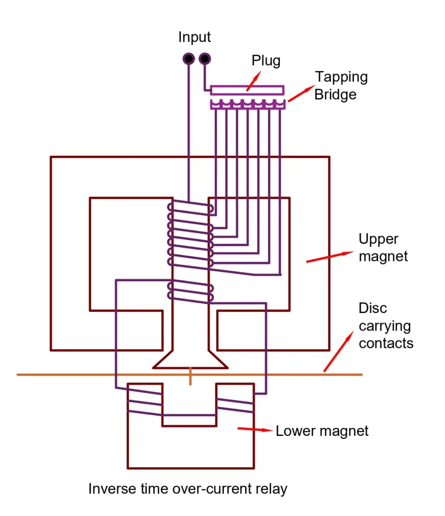
The induction disc carries a contact point. During an overcurrent situation, the disc rotates and closes the contacts of the circuit breaker. As a result, the circuit breaker immediately trips open the circuit and protects the system from the overcurrent fault.
If the delay time is set to zero, a definite-time relay works like that of an instantaneous relay.
The advantage of such relays is that they are reliable in places where speedy operation is sought to protect the system from surges. The inverse-time characteristic ensures protection at a higher speed when the current passing through the system is higher. It has a higher speed than that of a definite-time relay. These relays are present in both electromechanical types as well as microprocessor-based types.

There are the following types of inverse-time relays based on their time of operation.
- Normal Inverse time overcurrent relay
- Very Inverse time overcurrent relays
- Extremely inverse time overcurrent relay
- Long Time Inverse overcurrent relay
Inverse Definite Minimum Time (IDMT) Relays

Normal Inverse Relay
These relays have smaller operating times with a change in the current magnitude changes. These relays are used in utility systems.
Very Inverse Relay
The overcurrent relay with the very inverse characteristic curve is used in the feeder and on long transmission lines. The fault current falls at a rapid rate in the transmission line and therefore this relay curve is suitable for the protection of the transmission line.
Extremely Inverse Relay
The extremely inverse relay has an extremely large characteristic time as compared to IDMT and the very inverse relay. The relay trips faster when the pickup value exceeds the relay setting time. The relay is used for the protection of cables and transformers. This relay is used for protecting the cable, transformer, etc.
Long Time Inverse Overcurrent Relay
The relay has an extremely long operating time. These relays are used for those installations where there is a low risk of faults because these relays are not as sensitive as other types of overcurrent relays. It can take up to 60 seconds for clearing the fault.
A purely inverse-time relay is an ideal relay where the speed of operation increases commensurate with the amount of the overcurrent. In a practical scenario, however, an inverse-time relay has its own limitations.
As the current input to the system rises, the current transformer output rises causing the induction disc to rotate at a rapid speed and cause the circuit to break. But if the fault current is severely high, the core of the current transformer saturates.
Thus, the current output from the secondary of the Current Transformer stops rising proportionally even though the primary current rises because further magnetization of the CT stops. As a result, the induction disc of the relay can’t operate at a higher speed than that at the point of saturation of the current transformer.
Hence, the speed of the induction disc at the point of saturation is known as its maximum speed of operation. This is the minimum possible time for the relay to operate and it can’t be reduced further hence the name “ minimum time ”. The relay from this point onwards operates like a definite-time relay irrespective of the amount of rise in the current.

Applications of Overcurrent Relays
The really is used for protection of the following equipment.
- Feeder line protection
- Transformer Protection
- Motor Protection
- Capacitor bank protection
- Transformer Faults and Transformer Protection Schemes
- ANSI Device Numbers
- Classification of Relays | Different Types of Relays
- Difference Between Relay and Circuit Breaker
- Thermal Overload Relay- Working Principle, Types
Leave a Comment Cancel reply
Save my name, email, and website in this browser for the next time I comment.
EE Power School
Learn all about Electrical Power Engineering
Overcurrent Relay: Theoretical Concepts & Design In Simulink
Last Updated on September 8, 2018 by Muhammad Sarwar 8 Comments
Overcurrent relay are deployed extensively in the electric power system . They provide protection to important power system equipment including power transformers, generators, transmission lines, loads, motors, busbars etc. They are employed as primary protection as well as backup protection.
is is tutorial provides a theoretical foundation on instantaneous and definite time overcurrent relays. Overcurrent relay characteristics for both types of relays are discussed. A step-by-step guide on designing and testing Instantaneous and definite time overcurrent relays (DTOC) in Matlab/Simulink is also provided.
Table of Contents
Introduction:
Overcurrent Relays are frequently used in power network systems because in most of the faulty conditions current generally increases beyond its design limits. So, in most of the common faults, overcurrent relays play their role and provide the signal to the circuit breaker to isolate the faulty line from the remaining system. In this tutorial, the theoretical foundation of overcurrent relay is formulated and it will be designed in MATLAB/Simulink.
Overcurrent time protection is a selective type of overload and short-circuit protection used mainly in radial networks with single-ended feed as found in medium-voltage systems. A radial network is shown in the figure below.

Most protective devices of this kind also serve as a backup measure for differential and distance protection in the case of transformers, machines and transmission lines. The protective device is energized (excited) by a short circuit current I K or an overcurrent I > which significantly exceeds the operating current I N . To obtain an adequate measurement variable for the protective device, the current is coupled out via a current transformer and measured. If the current exceeds the set threshold, this is considered as the start command for the relay’s preset time delay. If the excitation is still present after the time delay, the protective device performs the desired action: The output relay is actuated, thereby triggering the circuit breaker. Otherwise, the action is cancelled.
Simple overcurrent protection is non-directional, i.e. its decision criteria only comprise the measured amperage and length of the Simulink phase. For overcurrent to result in energization, the threshold value must lie below the minimum short-circuit current occurring in the system. The reset value at which the protective relay returns to its initial position must be higher than the operating current. the results in a hysteresis defined by the reset ratio R (ratio of release and response values). In modern protective relays, this ratio is approximately R = 0.95 for overcurrent energisation. A reset ratio of R = 1 would pose a risk of chatter, i.e. uncontrolled engagement and release by the protective device.
Overcurrent Relay Characteristics
Overcurrent time protection can have a directional or non-directional trip characteristic. The single-stage trip characteristic of non-directional, maximum-overcurrent time protection is shown in Figure 2 and functions as described above.

A disadvantage of the simple trip characteristic is that the delay time is always the same, regardless of the fault current’s amperage. An excessively long delay time in the event of a fault can result in considerable damage to components. For this reason, most protective devices provide a choice of two or more tripping ranges. Figure 3 shows a distinction between the “overload” and “short circuit” ranges. If the excitation level lies the I > and I >> , tripping takes place at instant t > (overload stage). At very high amperages beyond I >> , such as those occurring during short circuits, tripping takes place sooner at instant t >> (short-circuit stage).

If several protective devices are connected in series across the network, this leads to a graded curve (Figure 4), the nearest protective relay being tripped in the event of a fault. If a protective relay fails, the previous one acts as a backup with a longer tripping time.

Fig. 4: Network map with non-directional, maximum-overcurrent time protection relay
The disadvantage here is that a fault in the vicinity of the feed point, where the tripping time t > is longest, results in the highest current. Consequently, additional protective measures are needed here.
Application of Overcurrent Relay in Power System
The overhead transmission line receives a three-phase power supply and is loaded symmetrically at its end. Located before the transmission line is a circuit breaker (power-switch module) for disconnecting the line from the power supply in the event of a fault. The time overcurrent relay measures the current in each phase via a current transformer.
Set up the experiment as shown in the circuit diagram and layout plan below.

Circuit diagram of an overcurrent relay
Activity 1: Design of Instantaneous Overcurrent Relay
Follow the instructions given below
- Open MATLAB.
- Open SIMULINK Library or write Simulink in command prompt and press ENTER.
- Select new model or press Ctrl+N.
- By using commonly used blocks, Simulink->Sources and Simscap -> SimPowerSystems, draw the following diagram.

Overcurrent relay has the in MATLAB. It is not present in SIMULINK library so follow the steps given below
- Take the subsystem block from ‘commonly used blocks’.
- Double click the block. A new window will open.
- Draw the following circuit diagram in the newly opened window.

For three phase source and load, use the typical values.
For fault timer settings, use the following figure.

Run the simulation for 5secs and use ode23s as the solver.
- Observe the current output waveform and make some comments on it.
- Reset the relay at 1.7secs and 3.7secs and observe the current output. Is it the expected required output? Make some comments on it.
- Make necessary changes in overcurrent relay circuit so that if it is being reset at 1.7secs it should allow the normal current to flow until fault occurs again at 3secs and reset is applied again at 3.7secs and normal current again starts to follow.
Activity 2: Design of Definite Time Overcurrent Relay
In an inter-connected power network system, it generally happens that load increases for a short period of time or any surge comes in the system. This is not a very serious condition because the time for this disturbance is very small and it is not an intelligent step to shut down the whole system. The shut of the whole system and its restart is a costly process so we need a relay which could sense the fault in a more intelligent way as compared to the over-current relay. For this purpose, definite time overcurrent relay is used. This relay has two features. 1st the current should be higher than the preset value and secondly, the fault should persist for the minimum time which has been set in the relay. If any one condition of the above two is not true then the relay will not operate and the system will operate normally.
Design a definite time overcurrent relay based on the knowledge gained in the previous activity. Use the same circuit diagram as was used in the design of instantaneous overcurrent relay. Your overall circuit diagram should look like the following figure.

We hope this article helped you learn the basics of overcurrent relay. You may also want to read our articles on the implementation of protection schemes in ETAP and Load flow analysis of a power system .
If you liked this article, then please subscribe to our YouTube Channel for video tutorials and project descriptions. You can also find us on Facebook . Give us your feedback in the comments section.
About Muhammad Sarwar
Muhammad Sarwar is an Electrical Engineer by profession and a blogger by passion. He loves to teach and share knowledge. He reads books, play games, blogs and program in his spare time.
Isaac Kofi Mensah says
March 10, 2022 at 7:11 PM
Hello Mohammad,
Please can I have personal email.
Thank you Isaac.
March 10, 2022 at 7:08 PM
Hello Mohammad
Trust you are doing well. Please teach me how to input the Discrete RMS Value Simulink Block parameters for DTOC relay design.
Best regards, Isaac.
December 25, 2021 at 8:47 PM
Dear Mohammad,
Please thanks for the knowledge you share. Is been a great help and education.Please I have designed a definite time relay but when simulation one of the parameters records error. Kindly assist.
Many thanks. Isaac
rakesh says
January 11, 2021 at 12:08 AM
send me the model files all of them
November 13, 2020 at 9:16 AM
hello i really like the work is there any way i can get simulink model for test definite over current relay?
Arshad Rasheed says
November 12, 2018 at 12:58 PM
Dear Muhammad Sarwar
I am Arshad Rasheed Lab engr in Rippah Uni Fsd and I need simulation of Definite Time Over Current Relay Simulation. Could you please send me.
October 17, 2018 at 10:04 PM
Do have any information on how to design a differential relay in Simulink?
Mohsin Shafi says
November 4, 2019 at 12:15 AM
Check youtube videos dear
Leave a Reply Cancel reply
Your email address will not be published. Required fields are marked *
About EE Power School
EE Power School is an online platform that offers educational resources, tutorials, and training courses for electrical engineering students, professionals, and enthusiasts. The website provides a wide range of content related to power electronics, renewable energy, and control systems, among others, to help learners enhance their knowledge and skills in the field.
Never Miss a Post
Receive latest articles in your Inbox!
Inverse Time Overcurrent Relays and Curves Explained

Overcurrent relaying is one of the simplest and most economical types of protection employed for power system feeders, transformers, generators, and motors. From the era of basic electromechanical elements to the contemporary use of advanced microprocessor applications in modern relays, overcurrent protection has been at the core of power systems for centuries.
The characteristics of overcurrent relays are based on operating times typically governed by a time vs. current curve. There are three main types of overcurrent relay: (1) Instantaneous, (2) Time-Dependent (Definite time or inverse), and (3) Mixed (Definite time and Inverse).
1. Instantaneous relays have operating times usually less than 3 cycles. These relays operate without an intentional time delay, hence they are referred to as instantaneous units. The pickup current is adjustable, and the application engineer can choose various settings from a wide range.
2. Time-dependent relays, as the name implies, operate with an intentional time delay. The pick-up current (minimum current at which the relay operates) and the time before trip are both adjustable.
There are a total of five types of time dependent relay, broken into two categories: Definite-Time and Inverse-Time.
A. Definite-time relays operate with an intentional time delay that is adjustable along with the current pick-up level. Although these relays are adjustable, their time delays are not necessarily dependent on the current value.
B. Inverse-time relays have an operating time depending on the magnitude of the current, generally with an inverse characteristic (the operation time of the relay is smaller as the current gets larger). These relays also have two settings: the pick-up current and the curve type.
In electromechanical relays, the curve is set by means of a dial, which is why the setting is referred to as the “time dial setting” or TDS. In some relays, a Time Dial Multiplier is used instead of the Time Dial setting, but their functions are similar.
TOC & IDMT
Inverse Time Over Current is also referred to as Time Over Current (TOC) or Inverse Definite Minimum Time (IDMT), indicating that the trip time of the relay is inversely proportional to the applied fault current.

The trip time of an inverse curve is calculated from the following parameters:
- Trip curve: Selected from the standard set of IEC and IEEE curves.
- Relay pickup current (A): The electrical current pickup set point Is in the relay.
- Fault current (A): The expected short circuit fault current I.
- TMS or TD setting: IEC time multiplier setting (TMS). IEEE time dial (TD).
Degrees of Overcurrent Inverse Curves
The time it takes for the relay to trip will vary depending on the curve slope. These curves can be used by engineers to coordinate with other protective devices upstream for selectivity and backup.
Their time-current characteristic curves are:
- Definite minimum (CO-6)
- Moderately inverse (CO-7)
- Inverse (CO-8)
- Very inverse (CO-9)
- Extremely inverse (CO-11)

When plotted on a chart, the different characteristics between each curve become apparent. The more inverse the curve shape, the greater difference in trip times.
Electromechanical overcurrent relays are often constructed to a specific curve shape, such as the ABB CO-6, CO-7, CO-8, etc. Changing the electromechanical curve shape means replacing the entire unit, which can be very expensive and results in surplus equipment.
Modern digital relays are programmable, allowing curve shapes to be easily changed without the need for replacement.
How Inverse Time Curves are Calculated
Each standardized relay protection curve will have its trip time calculated from either IEEE C37.112 or IEC 60255 equations.
IEEE C37.112-1996 Equation for Trip Time

- A = Time factor for over-current trip
- I = Actual Current
- I s = Relay Pickup Setting
- p = Exponent for inverse-time
- B = Timer coefficient for over-current trip
Note: IEEE C37.112-1996 does not specify coefficients in its standard curve equation, and therefore, each manufacturer’s curve is similar. A TDM (Time Dial Multiplier) is sometimes used instead of TD (Time Dial). The relationship is: TDM = TD / 7.
IEC 60255 Equation for Trip Time

- Is is the current setting.
- I is the actual current.
- k and α are the curve type constants.
A. Calculate the tripping time for a relay set at 1000A pickup current and TMS setting of 1 (IEEE Very Inverse) with 10kA of fault current.
- 10000 / 1000 = 10
- 19.61 / 99 = 0.198
- 0.491 + 0.198 = 0.689
0.689 Seconds
B. Calculate the tripping time for a relay set at 1000A pickup current and TMS setting of 1 (IEC Very Inverse) with 10kA of fault current.
- 13.5 / 9 = 1.5
1.5 Seconds
Mixed Curves (Definite time and Inverse) Overcurrent Relays
Thanks to the advent of the digital relay, its possible to have all of the advantages that come with the different types of relay elements packed into a single programmable unit.
Nearly any combination of instantaneous, definite-time, and inverse-time elements may be used. The most common type of mixed relay is the inverse definite with minimum time lag relay (IDMT) which combines inverse characteristic plus definite time characteristics.
Related: Protective Relay Testing and Maintenance Overview

- Power System Protection: Overcurrent Protective Relays (Archived)
- ABB CO Relay Manual
- IEEE C37.112-2018 - IEEE Standard for Inverse-Time Characteristics Equations for Overcurrent Relays

- Popular Topics
- Latest Topics
- Forum Archive
- News and Announcements
- Articles & Guides
- Electrical Testing Talk
- Productivity Tools
- Webinar Agenda
- Industry Links
- Terms Library
Certification Training
- Practice Exams
- ETT Study Guide
- QEMW Study Guide
- CET Study Guide
- Recommended Reading
- Certification Archive
- Start Your Career
- Connect & Discuss
Help and Support
- How to Sign Up
- User Guidelines
- Privacy Policy
- Terms of Service
- All Help Topics
Popular Topic Tags
This website is not affiliated with, maintained, authorized, endorsed or sponsored by the International Electrical Testing Association (NETA) or any of its affiliates. The information presented on this website should not be used to replace any kind of classroom or group study led by a certified instructor. The use of all copyrighted material on this website is provided for the purposes of teaching, scholarship, and research, and is therefore considered to be covered as "fair use" as specified in 17 USC § 107 - Limitations on exclusive rights: Fair use. If you are the owner of copyrighted material on this website and feel that our use of such material is not covered under 17 USC § 107, please contact us. TestGuy.net is a participant in the Amazon Services LLC Associates Program, an affiliate advertising program designed to provide a means for sites to earn advertising fees by advertising and linking to amazon.com. Copyright © 2024 TestGuy.net. All rights reserved.

What Is Overcurrent? (Causes, Effects, and Protection)
Overcurrent is a destructive fault that can damage small, as well as, large motors, electric devices, and home appliances.
In this article, I will discuss the current increase (overcurrent) and answer the most important questions about it. let’s get started.
Table of Contents
what is overcurrent?
Overcurrent refers to an electrical condition in a circuit where the current flowing through the conductors exceeds the rated or designed current-carrying capacity of the components, such as wires, fuses, circuit breakers, and other protective devices.
Overcurrent can occur due to various factors and can have different consequences, including overheating, component damage, fires, or circuit malfunction.
Overcurrent example
A clear overcurrent example is, when a motor with a rated current of 35A, you can find rated current on the motor nameplate, draws 55A for any reason, it can be a mechanical loading as I discussed in the article Motor Overcurrent , this motor is an overcurrent situation.
Another example is if a current of 167A passes through a cable with a current ampacity of 135A, this cable is over the current situation.
In general, any electrical equipment has a rated current, whenever the current exceeds this value, it’s an overcurrent situation.
Overcurrent effects

Uncontrolled electric overcurrent leads to excessive heat generation and can damage or burn equipment.
A circuit wiring overheats when an overcurrent occurs. There is a possibility that the insulation could melt, and fire can break out as a result.
Circuit overload causes the breaker to trip, opening up and shutting off the power supply. The overload could cause the wiring to overheat and melt, causing a short circuit and leading to a house fire.
In addition to the heat loss from increasing current, the rising current can also:
- Damage the circuit
- Burn resistors and electronic components
- Damage to electric equipment and home appliances
- And even cause fire to break out around the circuit.
What causes overcurrent in a circuit?
Overcurrent in electrical circuits can occur for various reasons, and it is important to identify and address the underlying causes to maintain the safety and proper functioning of electrical systems. Here are some common causes of overcurrent:
Excessive Load : One of the most common causes of overcurrent is simply overloading a circuit. This happens when the total electrical load connected to a circuit exceeds its designed capacity. Examples include plugging too many appliances into a single outlet or running too many devices on a circuit.
Short Circuits : A short circuit occurs when there is a low-resistance path between two conductors, causing a rapid and excessive flow of current. This can result from damaged insulation, exposed wires, or loose connections. Short circuits are particularly dangerous and can lead to electrical fires.
Ground Faults : Ground faults occur when an unintended electrical connection is established between a live conductor and the ground (earth). This can happen due to damaged insulation or faulty equipment. Ground faults can lead to overcurrent situations and pose safety hazards.
Equipment Malfunctions : Malfunctions within electrical equipment, such as motors, transformers, and appliances, can cause overcurrent. This can be due to internal faults, mechanical issues, or electrical problems within the equipment itself.
Power Surges : Sudden and temporary increases in voltage, known as power surges or voltage spikes, can cause overcurrent in circuits. These surges can result from lightning strikes, utility grid fluctuations, or switching events.
Inrush Current : Some devices, particularly motors and transformers, experience high inrush currents when they are initially energized. Inrush current can temporarily exceed the normal operating current and may trip protective devices if not accounted for in the design.
Circuit Imbalances : In three-phase electrical systems, imbalances in current between the phases can lead to overcurrent in one or more phases. This can occur due to unequal loads or issues with the supply system.
Faulty Wiring and Connections : Poorly installed or deteriorated wiring and connections can increase electrical resistance, leading to overheating and overcurrent. This can be a result of corrosion, loose connections, or inadequate wire size.
Environmental Factors : Environmental factors, such as extreme temperatures, humidity, or exposure to corrosive substances, can degrade wiring and insulation over time, potentially causing overcurrent issues.
Circuit Design Flaws : Errors or flaws in the initial design of electrical circuits, including the selection of protective devices and wire sizes, can lead to overcurrent problems if the circuit is not properly matched to its intended use.
To prevent overcurrent and its associated risks, electrical systems are designed with protective measures, including circuit breakers, fuses, and ground fault circuit interrupters (GFCIs).
These devices are selected based on the expected load and potential risks associated with the circuit.
Regular maintenance and inspections are also essential to identify and address any issues that may lead to overcurrent.
How can you prevent over-current?
Electrical circuits have circuit breakers , surge protectors, and electrical fuses to prevent potential disasters.
The concept of preventing a power outage due to an overcurrent is quite straightforward: you should avoid overloading a circuit in the first place.
There are typically separate circuits for each room of the house, with heavy-duty appliances like an electric dryer or oven requiring a separate dedicated line.
In order to prevent your circuits from overcurrent, let us take a look at how you can do it.
Your circuit load should be calculated
For the workplace, never run any power tool or electrical equipment before you check its power rating, and verify the power source is suitable for it.
Only authorized persons are allowed to add new loads to any power source.
All authorized departments should participate when choosing new equipment. For example, when choosing a new pump, electrical and mechanical engineers should cooperate to make sure the pump and the motor ratings are the same, to prevent motor overloading.
For home circuits, the majority of circuits are rated for 15 to 20 amps, and if you understand how much current your lights and appliances use, you can roughly estimate how much current is safe to put in.
It may be necessary to move the light strand to another room if your load is approaching 80% before plugging in the next strand to avoid overcurrent.
- Never use extension cords without asking an authorized electrician.
- Never overload the outlet with a lot of appliances.
- Ask for advice before connecting any new appliance.
- If you buy a new house, hire an authorized electrician to check its circuits and wiring.
Use large appliances with caution
When searching for a location to plug your lights in, it’s a good idea to stay away from spaces that already include a lot of equipment, such as the kitchen.
To make more current available for those priceless decorations, you may disconnect any equipment or devices you don’t intend to use to avoid overcurrent.
Make LED lighting a priority
Investing in LED lights is one method to make your current setup considerably more festive.
LED lights consume significantly less power than conventional bulbs, saving you money on your electricity bill and easing the pressure on your wiring to avoid overcurrent.
Use Protection devices
The built-in defense against overcurrent in your home is the circuit breaker. They are housed in your electrical panels and turn off electricity to particular areas of the structure if they detect erratic electrical currents.
You may protect yourself against short circuits, when necessary, by doing routine circuit breaker maintenance to make sure it is operating correctly.
Why does the current increase when the load increases?
Each load requires its own current, the more connected loads, the higher the current they draw. To explain it to you, suppose the electrical circuit is a pipeline, the loads are faucets, and the more faucets you open the more water you draw.
In the case of electrical Motors
In case we have a motor (the load), this motor requires electric current depending on its power rating.
If the motor starts with no load, it draws a no-load current, it’s smaller than the full-load current.
By increasing the mechanical load, the motor needs to provide more torque to overcome this load, and of course, it will draw more current .
In case of home loads
In case of connecting more loads on home or a building outlet. Electrical loads are typically connected in parallel.
If you have a load raised, it means the added load is connected in parallel with the existing load.
Parallel connections always decrease the equivalent impedance. Therefore, the current increases.
When loads are connected in parallel, each load draws its own currency from the circuit according to the requirements of that load. Therefore, the current increases when the load is increased.
How can I tell if my electrical panel is overloaded?
If your panel main circuit breaker trips , and when you turn it on again it works for a while and then trips again, it’s a clear sign of a possible overloaded panel.
But, keep in mind that there are other reasons for circuit breaker tripping, you can hire an electrician to measure the currents of the panel, check the man circuit breaker rating, and make sure it’s overloaded.
If you know how to use a current clamp, you can measure the current by it, check the circuit breaker rating, and make sure the CB rating is greater than the measured one.
Make sure to switch on all loads during the measuring process, this is the only way to have a clear idea about the panel load.
One more thing, an electrical engineer can calculate the panel loads, check the circuit breaker’s ratings, and make sure it’s not overloaded.
It’s crucial to watch out for clues that your electrical panel could be generating an excessively high level of electricity when you start putting in more and more appliances for any reason.
To assist you in recognizing when this could be happening, we’ve listed a few telling indications.
Panel Overheating, the overheating that might result from excessive current flowing through your breakers or cables is also a sign of an overloaded panel.
In my workplace, we use thermal imaging to check that panels are not overloaded.
What happens when an electric current increases?
When the electric current increases, the following points can happen:
In the case of electric motors
The higher the current, the higher it temperature rise. This temperature increase can cause the motor insulation to fail, and lead to an internal short circuit between windings and complete damage if the protection device fails to trip the circuit.
In the case of home wiring
Excessive current trips the circuit breaker of your home panel. Of course, it will increase the temperature of the wiring, the panel, and the circuit breaker.
If the increased current is caused by an appliance, the appliance will get damaged if the CB fails to trip.
Ready to dive in? Check out my comprehensive article Avoiding Overcurrent Situations: Tips to Keep Your Circuits and Devices Safe now
In the case of electric cables
Cable temperature rise can cause the insulation to get damaged. When the insulation gets damaged, the live phase and the neutral or another phase will get in touch and a short circuit happens.
In the case of an electric generator

The generator will heat up, its winding insulation will melt and a short circuit occur between its phases. Yep, it’s complete damage.
We can say, that an overcurrent could cause the circuit wiring, as well as the electrical equipment to overheat. This could lead to, equipment damage or melting of the insulation and a possible fire.
The heat loss from increasing current can cause damage to the circuit, burn resistors, damage electrical equipment and home appliances, or even cause fire to the surroundings.
Circuits are designed to work with a particular voltage and resistance . If the excessive current flows in a conductor , the results will be very bad if the protection device fails to trip the circuit.
Why does the current increase in temperature?
From a physics point of view.
Electric current is the flow of electrons in a conductor. As the current increases, the electron flow will increase.
Due to the increased flow of electrons, the collision of electrons will intensify generating heat energy and power losses. This is why the electric current increases the temperature.
From an electricity point of view,
any conductor has a resistance, when current flows through the conductor it faces its resistance.
From the power equation we have, Power = I 2 *R, which means that increasing ‘I’ and the ‘R’ increases the power loss in the shape of heat and raises the temperature.
The temperature rise beyond the allowed limits on any device is directly linked to the fact that you have exceeded power consumption higher than the rated value.
Any equipment is designed to meet a specific power consumption, if the limit is exceeded its power, gets heated.
ِAny electric current value causes produce temperature, the more current the higher the temperature rise.
Starting from the equipment-rated current to the overcurrent and ending at the short circuit current. All these currents produce heat, and the value of the temperature rise differs from one currency to another.
Read also my article about Electric transformer temperature rise . and the other one , Motor temperature rise causes and limits.
Why does an increase in current increase power losses?
Power loss is a result of the conductor resistance that the current faces while passing through the conductor.
As you can see, from the below power loss equation, the power is proportional to the square of the current. So, if the current increases, the power losses will increase much faster.
As we know, Power = I 2 × R, This means, the higher the current the higher energy loss in the conductor in the form of heat . As I mentioned above.
The increase of power loss in the conductor increases the conductor’s temperature. We don’t have an ideal conductor with zero resistance, if we do its power loss will be zero.
What is Overcurrent Protection?
Overcurrent protection is a fundamental aspect of electrical safety that involves the use of devices and measures to detect and limit excessive electrical current in a circuit.
The primary purpose of overcurrent protection is to prevent electrical circuits and equipment from being subjected to current levels that exceed their designed capacity, which can lead to overheating, damage, fires, and safety hazards.
Overcurrent protection is achieved through various protective devices and strategies, including:
Fuses : Fuses are passive overcurrent protection devices that consist of a wire or element that melts or breaks when subjected to excessive current. When a circuit experiences an overcurrent condition, the fuse element melts, opening the circuit and disconnecting power. Fuses are available in various ratings to match the current-carrying capacity of the protected circuit.
Circuit Breakers : Circuit breakers are automatic overcurrent protection devices that can be reset after they trip. They consist of a switch-like mechanism that opens the circuit when an overcurrent condition is detected. Circuit breakers are available in different types, including thermal-magnetic and electronic, and they can be designed to provide protection against short circuits, overloads, or both.
Ground Fault Circuit Interrupters (GFCIs) : GFCIs are specialized overcurrent protection devices used to prevent electrical shock hazards. They detect imbalances in current flow between the hot and neutral conductors and trip the circuit if a ground fault is detected. GFCIs are commonly used in locations where electrical devices may come into contact with water, such as bathrooms and kitchens.
Arc Fault Circuit Interrupters (AFCIs) : AFCIs are designed to detect and interrupt arcing faults, which can lead to electrical fires. They monitor the circuit for abnormal arcing conditions and trip the circuit if such conditions are detected, reducing the risk of fire.
Motor Overload Relays : These are used to protect electric motors from overcurrent conditions that can occur during motor startup or due to mechanical problems. Overload relays monitor the motor’s current and trip the circuit if the current exceeds a specified threshold for an extended period.
Current Limiting Devices : These devices are designed to limit the magnitude of fault currents in a circuit, reducing the potential damage caused by short circuits and overcurrent events.
Selective Coordination : In complex electrical systems, selective coordination is a strategy that involves coordinating the settings of protective devices (e.g., circuit breakers and fuses) to ensure that only the device closest to the fault opens, minimizing downtime and disruptions in the event of an overcurrent condition.
Proper Circuit Design : Ensuring that circuits are appropriately designed with proper wire sizes, protection devices, and load considerations is essential for overcurrent protection. Designing circuits to match the expected loads and operating conditions helps prevent overcurrent situations.
Overcurrent protection devices and strategies are critical for electrical safety, as they help prevent electrical fires, equipment damage, and electrical hazards.
The selection and installation of the appropriate protective devices depend on the specific requirements and characteristics of the electrical circuits and equipment being protected.
Over-current protection importance
In order to keep yourself and others safe from many risky situations, overcurrent protection is important.
Every electric circuit must have circuit overcurrent protection. If the current levels of an electric circuit exceed the safe limits for which they were built, the circuit may be harmed or even destroyed.
Circuit wires may become too hot if there is an overcurrent. In turn, fire and insulation melting might result due to this situation.
There may be serious consequences if a circuit is not equipped with overcurrent protection. An electrical shock, fire, or electrocution can result from overcurrent, which can destroy unprotected electronic devices and cause human injury and fatality.
The purpose of an overcurrent protection device is to protect against dangerously high temperatures in conductors or their insulation . It is crucial to match the conductor size and current rating of the protection device.
We can say, that overcurrent protection is essential because it protects humans and equipment as well against destructive and fatal accidents.
Is current protection and surge protection the same?
No, it’s different; overcurrent protection protects the excessive current flow in the circuit, and surge protection protects against excessive voltage or spikes of voltage to the circuit.
Overcurrent protection is the protection against excessive currents beyond the acceptable current rating of the equipment. It generally operates instantly.
Magnetic circuit breakers, fuses , and overcurrent relays commonly provide overcurrent protection.
High and low-voltage power distribution systems, as well as control systems, frequently incorporate overcurrent protectors.
On the other hand, Surge protection protects equipment against power surges and voltage spikes while blocking voltage over a safe threshold.
When a threshold is an overrated voltage, a surge protector shorts to ground voltage or blocks the voltage.
Low-voltage power distribution systems frequently utilize SPD, sometimes referred to as surge protector, lightning protector, and lightning arrester, as a lightning protection device.
It is often linked to the line in parallel or series to discharge the wave.
Difference Between Overcurrent and Overload Protection
Overloading equipment causes it to draw an overcurrent. We, electrical engineers, usually use the word overload in case the equipment gets more load, electrical or mechanical, than it’s designed to handle.
For example, a motor is overloaded means its mechanical load is greater than the motor-rated power so, it draws an overcurrent.
Another example is when a cable is overloaded, it means the cable load, electrical load, draws current greater than the cable current carrying capacity, so the cable has over current passing through it.
Overcurrent protection is the protection against excessive currents beyond the acceptable designed current rating of equipment or an electric device . Short circuits, arc faults,s, and earth faults are overcurrent types.
On the other hand, overload protection is protection against overloading equipment that causes it to face an overcurrent situation, and would cause the equipment to overheat.
A well-designed circuit and periodical inspection of loads can help prevent overload
Hence, an overload is also some kind of overcurrent. Slow-acting fuses and overload relays are commonly used for overload protection devices.
A thermal-magnetic CB as well as the dual element fuse has both thermal and magnetic elements which means that it could provide both overcurrent and overload protection.
How does overcurrent protection work?
According to the circuit current rating of equipment or circuit, overcurrent protection devices have a current rating.
In case of any fault, when the circuit current exceeds the rating current of protection devices, it cuts the circuit’s supply, by the thermal or magnetic effect of the overcurrent. As you know, current has both thermal effects, and if the current passes through a coil it will produce a magnetic effect.
The thermal effect can melt a fuse to protect the circuit and can trigger the mechanical mechanism of a circuit breaker to trip the circuit.
The magnetic effect also can trigger the circuit breaker faster than the thermal effect. By using this working principle, overcurrent protection devices protect equipment or circuits.
The thermal effect is used for overload protection, lower values of overcurrent, while the magnetic effect, the faster, is used for protection against the short circuit over currents.
Fuse and circuit breakers are overcurrent protection devices that contain time/current characteristics (TCC) that specify how long it takes to clear the fault for a specific value of fault current. The higher the overcurrent value, the faster the tripping time of the circuit breaker.
The fuse’s metal strip or wire melts when too much current flows across it, cutting off the current flow. Fuses are sacrificial components, which means an overcurrent destroys them.
On the other hand, circuit breakers turn off when they face any fault or a short circuit, unlike fuses, which melt to break the circuit. Circuit breakers can therefore be reused.
Can overcurrent damage an overcurrent protection device?
Yes, overcurrent can potentially damage an overcurrent protection device, such as a fuse or a circuit breaker, if the device is subjected to current levels exceeding its rated capacity for an extended period.
While these protection devices are designed to withstand short-term overcurrent conditions and perform their protective function, they are not invulnerable and can be damaged under certain circumstances:
- Sustained Overloads : If a circuit experiences a sustained overload, where the current exceeds the device’s rated capacity for an extended period, it can cause overheating of the protection device. Prolonged overheating may damage the device, affecting its ability to function properly in the future. For example, a fuse may blow or a circuit breaker may trip due to overheating.
- Fault Currents : In the case of a short circuit or a severe fault current event, the magnitude of the current can be extremely high. While protection devices are designed to handle these situations and quickly interrupt the fault current, the stress from such high current levels can potentially damage the internal components of the device.
- Inadequate Device Rating : Using a protection device with an inadequate current rating for the circuit it is intended to protect can result in the device being damaged during an overcurrent event. For instance, if a lower-rated fuse or circuit breaker is used in a circuit with a consistently high current load, it may trip or blow repeatedly, leading to damage.
- Device Wear and Tear : Like any mechanical or electrical component, overcurrent protection devices can experience wear and tear over time. Frequent tripping, exposure to adverse environmental conditions, or improper handling can contribute to device degradation and reduce their effectiveness.
It’s essential to select protection devices with appropriate current ratings for the circuits they are intended to protect.
Regular maintenance and inspection of protection devices are also important to ensure their continued reliability and performance.
Damaged or malfunctioning protection devices should be replaced promptly to maintain electrical safety and prevent potential hazards.
Can over-current damage a circuit breaker?
Yes, overcurrent can potentially damage a circuit breaker, but circuit breakers are designed to withstand and interrupt overcurrent conditions within their specified ratings.
However, there are limits to their capacity, and extreme overcurrent events or sustained overloads can lead to damage or failure.
Here are some considerations regarding overcurrent and circuit breaker damage:
To prevent damage to circuit breakers and ensure their reliable operation, it’s important to adhere to the following practices:
- Select circuit breakers with appropriate current ratings for the circuits they protect.
- Avoid overloading circuits beyond their designed capacity.
- Properly maintain and inspect circuit breakers to identify signs of wear or damage.
- Replace damaged or malfunctioning circuit breakers promptly.
- Ensure that circuit breakers are operated within their specified voltage and current ranges.
While circuit breakers are designed to provide overcurrent protection and are more robust than fuses, they are not immune to damage under extreme or improper operating conditions.
Regular maintenance and adherence to electrical safety standards are essential to maintain the integrity and reliability of circuit breakers in electrical systems.
For more information about Why circuit breakers go bad, read my article.
What happens if an over-current protection device is oversized?
If an over-current protection device (such as a fuse or circuit breaker) is oversized for the circuit it is meant to protect , it can lead to several potential issues and compromises in electrical safety and equipment protection. Here are some consequences of using an over-sized protection device:
- Reduced Protection : The primary purpose of an over-current protection device is to safeguard the circuit and connected equipment from excessive current levels, which can cause overheating, fires, and equipment damage. When an oversized device is used, it may not trip or open the circuit as intended when overcurrent conditions occur. This means that the circuit and equipment may not be adequately protected from short circuits, overloads, or faults.
- Increased Fault Energy : An oversized protection device can allow excessive fault currents to flow without tripping or interrupting the circuit. This can result in higher fault energy levels in the event of a short circuit, increasing the potential for electrical arc flash incidents and equipment damage.
- Equipment Damage : Oversizing protection devices can lead to damage to downstream equipment. For example, if a circuit breaker with a much higher current rating than the circuit’s load capacity is used, the equipment connected to the circuit may not be adequately protected from overcurrents. This can lead to overheating and damage to the equipment, including motors, transformers, and wires.
- Inefficiency : Oversized protection devices can be less efficient in terms of energy consumption. They may allow unnecessarily high currents to flow for longer periods before tripping, leading to increased energy losses and potentially higher operating costs.
- Violation of Electrical Codes and Standards : Oversizing protection devices can lead to non-compliance with electrical codes and standards. Electrical codes specify the correct sizing and selection of protection devices based on the characteristics of the circuit and equipment being protected. Using an over-sized device may result in non-compliance and regulatory violations.
- Misleading Fault Analysis : Oversized protection devices can make it challenging to identify and analyze faults or overcurrent events within a circuit. Since the device does not operate as expected under fault conditions, troubleshooting and diagnosing electrical issues can become more complex.
To ensure proper electrical safety and equipment protection, it is crucial to select and install protection devices with current ratings that match the circuit’s load and characteristics.
The selection of protection devices should be in accordance with electrical codes and standards. Additionally, regular maintenance and testing of protection devices are essential to verify their proper operation and compliance with safety requirements.
Oversized protection devices should be replaced with appropriately sized ones to maintain electrical safety and equipment protection.
What if an overcurrent protective device opens slower than expected?
If an overcurrent protective device, such as a circuit breaker or a fuse, opens slower than expected, it can have several implications and potential consequences, depending on the specific circumstances and the nature of the overcurrent condition:
- Equipment Damage : Slower tripping of the protective device can allow excessive current to flow through the circuit for a longer duration. This prolonged overcurrent can result in overheating of wiring, equipment, and components, potentially causing damage or degradation.
- Fire Hazard : Overcurrents can generate heat, and if the protective device does not trip promptly, the prolonged overcurrent can increase the risk of electrical fires. Electrical components and insulation may become damaged due to excessive heat.
- Safety Hazards : Slower tripping of protective devices can pose safety hazards to individuals in the vicinity. For example, if a fault condition occurs and the circuit breaker does not trip quickly, it may expose people to electrical shock hazards.
- Compromised Protection : The primary purpose of overcurrent protection is to prevent electrical circuits and equipment from being subjected to current levels that exceed their designed capacity. When a protective device opens slower than expected, it compromises the protection provided by that device.
To address the situation when an overcurrent protective device is not operating as expected, here are some steps to consider:
- Investigation : Identify the cause of the slow operation. It could be due to a malfunctioning protective device, loose connections, or other issues within the electrical circuit.
- Immediate Shutdown : If there is an ongoing overcurrent condition and the protective device is not responding as expected, it is essential to de-energize the circuit immediately to prevent further damage or hazards. Disconnect power at the main switch or circuit breaker panel if necessary.
- Professional Inspection : Seek the assistance of a qualified electrician or technician to inspect the protective device, the circuit, and any associated equipment. They can diagnose the issue and recommend appropriate corrective actions, such as repairing or replacing the protective device.
- Maintenance and Testing : Regularly maintain and test protective devices to ensure they operate within their specified response times. Periodic testing and maintenance can help identify potential issues before they become critical.
- Replacement : If the protective device is found to be faulty or not operating correctly, it should be replaced promptly with a properly rated and functioning device to restore adequate protection.
Ensuring that overcurrent protective devices operate correctly and promptly is crucial for electrical safety and equipment protection.
Any signs of malfunction or unexpected behavior should be addressed promptly to prevent potential hazards and equipment damage.
Install my Free Android App on Google Play :
Electrical Cables Most Common Tables “Electrical Cables Tables”
And, my Electrical Calculations App “ Fast Electrical Calculator ”
Discover more great content by subscribing to My channel
Looking to stay ahead of the game in the world of electrical engineering? Subscribe to my YouTube channel and gain access to exclusive content you won’t find anywhere else!
The staff I recommend
(Amazon Affiliate Links to products I believe are high quality):
- Economy 120 Volt/60Hz AC Power Source – Step-Down Voltage & Frequency Converters 1800W
- UNI-T Digital Multimeter Tester UT139C
- 50-Amp Extension Cord for RV “100ft”
- Voltage Stabilizer 110/220v
- Hair Dryer “best selling “
- TOSHIBA EM131A5C-BS Countertop Microwave Ovens
Disclaimer : This contains affiliate links to Amazon products. I may earn a commission for purchases made through these links.
You Might Also Like

Current Transformer: 19 Useful Answers For Beginners
Prevent electrical fires with gfcis: here’s how they work.

What is Capacitor? What You Should Know!
What is electrical short circuit & why is it dangerous, what are current transformer types.


- _Transformer
- _DC Generator
- _Induction Motor
- _Synchronous Motor
- _Alternator
- _Special Motors
- Measurements
- _Measuring Instruments
- _Potentiometer
- _Measurement of Power
- _Measurement of Energy
- _Measurement of Resistance
- _AC Bridges
- _Transducers
- Power Systems
- _Transmission
- _HVDC Transmission
- _Switchgear
- _Protection
Types of Overcurrent Relay - Definite Time, Inverse Time & IDMT Relays
A protective relay that operates when the current flowing in the circuit reaches a predetermined value is called Overcurrent Relay. The predetermined value of the current at which the relay starts operating by initiating a trip signal is known as its pick-up value.
It is essential to protect each and every electrical equipment from overcurrents, hence overcurrent relay is the most widely used protective relay in a power system.
The applications of overcurrent relay include protection of distribution lines, industrial systems, large motors, power equipment, etc. Most of the overcurrent relays used for overcurrent protection are of electromagnetic type. But due to the rapid evolution of technology, numerical overcurrent relays based on microprocessors or microcontrollers are used nowadays for overcurrent protection.
Types of Overcurrent Relays :
Based on the relay operating time-characteristics, overcurrent relay can be classified into the following types, definite time overcurrent relay instantaneous overcurrent relay inverse time overcurrent relay inverse definite minimum time (idmt) overcurrent relay very inverse time overcurrent relay extremely inverse time overcurrent relay., definite time overcurrent relays :.
These relays operate after a predetermined time when the current exceeds its pick-up value. Here, the operating time of the relay does not depend on the magnitude of the current above the pick-up value. A time delay mechanism is provided to get desired operating time.
They are used in applications where impedance Z S between the source and relay is small compared with the impedance Z L of the section to be protected. They are also used to serve as a check against short-time asymmetrical currents.
Instantaneous Overcurrent Relays :
They operate immediately when the current exceeds its pick-up value without intentional time delay. it is given as, i 2 t = k (constant) where i is the current in the relay coil and t is relay time., they are used for fast relaying operations having an operating time of less than 0.1 seconds. used for differential protection of transformers inrush currents. back-up protection for differential and distance types of relays. they are used when the impedance between source and relay is less with respect to the impedance of the system to be protected., inverse time overcurrent relays :.
In these, the operating time of the relay reduces as the fault quantity increases in magnitude. Normal practice is such that they are more inverse when nearer to pick-up value and become less inverse as it increases. Inverse time relays are used where the source impedance is much smaller than the line impedance.
Inverse Definite Minimum Time (IDMT) Overcurrent Relays :
These relays have the combined characteristics of definite time and inverse time relays. The IDMT relays operate as inverse time relay i.e., there exists an inverse relationship between time and current for lower values of fault current. While for higher values of fault current the relay acts as the definite time relay where the operating time is independent of fault current.
The relay exhibits an inverse relation between operating time and fault current near pick-up value and becomes almost constant just above the pick-up value. IDMT relays are widely used for the protection of distribution lines or distribution feeders.
Very Inverse Time Overcurrent Relays :
These relays exhibit more inverse characteristics between time and current than that of an inverse time or IDMT relay. This type of relay saturation occurs at the later stages. The time-current characteristic lies between IDMT characteristic and extremely inverse characteristic.
These relays give better selectivity than IDMT. They are used in cases where source impedance is much smaller than line impedance. They are more suitable for earth fault protection because of their steep characteristics.
Extremely Inverse Time Overcurrent Relays :
The time-current characteristics for these relays are steeper than that of very inverse overcurrent characteristics. They are required for fuse coordination and thermal protection of transformers, induction motors, alternators, expensive cables, etc. These relays are used for reclosing distribution circuits after a long outage. Also used for load restoration purposes.
Time-Current Characteristics :
The time-current characteristics of different types of overcurrent relays are shown in the below figure.

The general expression for time-current characteristic is given by, t = K / (I n - 1) The following are the time-current characteristic of various overcurrent relays, For IDMT relays, t = 0.14 / (I 0.02 - 1) For very inverse time overcurrent relays, t = 13.5 / (I - 1) [n = 1] For extremely inverse time overcurrent relay, t = 80 / (I 2 - 1) [n = 2]
Do not enter any spam links and messages
Contact Form
- Online Training
- Access Your Courses
- Group Registration
- The Complete Relay Testing Handbook Series
- Book Extras
- Your Digital Downloads
- Hands-On Training Class Information
- Download Our Relay Training Brochure
- TechTalk (Our Blog)
- Add Your Post to TechTalk
- We Need Your Help!
- Why Choose Valence?
- About Chris Werstiuk
- Testimonials
- Contact Valence
- Subscribe to our Mailing List
- Your Shopping Cart
- The Relay Testing Handbook
- Your Account Info
No products in the cart.
Finding the Direction in Directional Overcurrent Relays
A reader recently asked a question about the forward and reverse directions described in the Directional Overcurrent Relay section of The Relay Testing Handbook series. I used electro-mechanical directional relays as an example, which may have been a mistake. Let’s take another look at the Directional Overcurrent (67) element from a system perspective.
We will start with a simple transmission line with the source on the left and a load on the right. The current flows into the polarity mark of the CT on Breaker 3, and into the Directional Overcurrent (67) Relay using the same direction. Any current flowing into the polarity mark is considered to be the forward direction.

The phasor diagram for this situation might look like the following. Every load is a combination of resistance and inductance, so the normal operating range for this line is the green shaded region when the current flows into Circuit Breaker 3.

Let’s look at what the Directional Overcurrent (67) relay connected to Circuit Breaker 4 sees under the same conditions. This relay is designed to protect the same transmission line from the other direction. The current enters the non-polarity mark of the CT, and the relay determines that current is leaving the transmission line; or the reverse direction.

The phasor diagram of a meter test on the Directional Overcurrent (67) relay connected to Circuit Breaker 4 would look like the following. The current is flowing in the reverse direction and the orange/red shaded area displays the normal region when the current flows into a load behind the relay.

If we reversed the source and load, you could swap the phasor diagrams above for each relay. Let’s shake things up by closing Circuit Breaker 8 and applying a Phase A-to-Ground fault 50% down the line. This is a fault, so:
- The faulted voltage should drop in proportion to the severity of the fault
- The fault current should be significantly larger than the normal load current.
- The fault current should lag the voltage by 40-89.9 degrees depending on the line characteristics, voltage, and severity of the fault.
- The non-faulted phases should stay relatively the same.
Both fault currents flow into the transmission line, so the directional overcurrent relays connected to Circuit Breakers 3 and 4 will see the current in the forward direction because the current flows into both CT polarity marks.

If we pretend that the fault is exactly 50% down the line, both sources are identical, and the impedance between the sources and the fault are also identical, we can use the same phasor diagram for both relays. Obviously this won’t be true in the real world and the current magnitudes would be different. The typical region for a fault in the forward direction occurs in the green shaded area for both relays.

Now let’s look at a fault that is not on the transmission line.

The fault current flows into the polarity mark of the CT connected to Circuit Breaker 3, so the Directional Overcurrent (67) relay sees the fault in the forward direction. If the fault current is larger than the overcurrent setting, the relay will trip.

Directional overcurrent protection schemes were replaced with line impedance relays (21) to prevent a situation like this from occurring. This relay’s primary purpose is to trip for faults on the transmission line, not for faults somewhere else on the system, as would happen here. A line impedance relay would recognize that the fault was not on the transmission line and ignore this fault unless it was programmed to also provide backup protection with a significant time delay.
The fault current flows into the non-polarity mark of the CT connected to Circuit Breaker 4, so the Directional Overcurrent (67) relay sees the fault in the reverse direction. The orange/red shaded region indicates the typical region for a fault behind a relay.

Overcurrent directional relays can be set to trip for faults in the forward direction, which will protect the equipment in front of the relay. Or they can also be set to trip for faults behind the relay in the reverse direction. Forward and reverse are typically determined by the normal flow of current into the relay, so be sure to confirm the CT connections before you make any assumptions.
Incorrectly determining forward and reverse is an easy mistake to make. If I ever have doubts about some relay settings or directional overcurrent tests, I usually ask the design engineer, “Did you mean to trip if the fault is on the transmission line, or on the buss?” (You can use whatever easy-to-define characteristic for your situation.) Once they answer that question, I will review the CT connections and build a test on the transmission line and see if it trips. I then apply the fault in the reverse direction to make sure it doesn’t trip. Always ask the engineer what they intended if there is any doubt.
You could also perform a test in either direction first and see what direction the relay is set to trip. If it doesn’t make sense to you, you can ask the engineer, “Did you mean for the relay to trip if there is a fault on the buss?”
I hope this helps clear up the definitions of forward and reverse for Directional Overcurrent (67) relays. The next post on this topic, “ Testing Directional Overcurrent Relays “, will hopefully help clarify the characteristic angle.
Please share this article or leave a comment if you found it useful . It may not seem like much, but it helps us keep creating more free content for you.
Also, as a bonus you can click the image below to sign up and we’ll send you the free Finding Direction in Directional Overcurrent Relays Cheat Sheet . It distills what we just covered into a simple 2-page PDF summary you can print out and take with you:
Did you like this post?
You can share it with these links:

About the Author
Chris Werstiuk
Chris is an Electrical Engineering Technologist, a Journeyman Power System Electrician, and a Professional Engineer. He is also the Author of The Relay Testing Handbook series and founder of Valence Electrical Training Services. You can find out more about Chris here .
Read More Articles:
Why did my Frequency Test in Cycles Fail?
CT Primary Injection Ratio Testing Problems
Leave a Reply
Your email address will not be published. Required fields are marked *
Thank you for valuable articles for beginner like me.
I want your advice about setting directional overcurrent relay. On your SLD above what is the setting value of relay 67 for CB no 3 and 4?
Is it possible to have lower setting value (lower than normal current flow) of relay 67 for CB no 4? This case happen during startup
The pickup setting would always be set higher than the expected maximum current flow. Otherwise the relay would trip under normal conditions instead of fault conditions.
Some directional overcurrent applications have a pickup current set lower than the expected current, but these applications are designed to separate two systems when the current flows in an undesired direction.
For example, imagine a plant supplies all of its own electricity and keeps a feeder connected to the grid to use during emergencies ,and to sell excess power to the utility. Power from this utility is very expensive, so they never want to take power from the grid. They could set a directional relay with a low pickup setting that will only operate if power flows from the grid to the plant. Power from the plant to the grid will be ignored.
A lot of thanks
Very very good explanation. Easy to understand. Thanks and keep it up!
Hello Chris,
I’m a beginner in this field and i am confused about Relay Operating Angle (ROA) and Relay Characteristic Angle (RCA) What is the difference between the two, could you please explain the use of each element?
Thank you in advance
Thanks for your question. Those terms could mean a variety of things. Can you send some context such as the source of these terms.
My question refers to directional overcurrent protection function, in some relays we just put the angle setting for RCA and in other relay we should set both RCA and ROA. The question is what is the use of ROA settings.
Thanks for your question. Unfortunately, I am unfamiliar with an “ROA” setting and don’t know what it is.
Thanks for your explanation. I have a question regarding reverse KVAR.
Will the 67 relay(Phase directional overcurrent) detect reverse current and trip the breaker if the capacitor bank power factor correction unit is feeding the utility with a substantial amount of KVAR due to the sudden decrease of the active load?
Some relays like GE UR relays allow you to define a specific direction with blinders, so those relays could be specified to look in any direction within a window. Other like SEL are looking for specific fault conditions, so they are less configurable in that way. Neither relay will properly determine VARs when using a 637 element. They can only apply current direction and magnitude. You would need to find a relay with a kVAR element to properly apply the protection you desire.
In 67 function. Can anyone explain on what basis do we chose the right setting for Relay Characteristic Angle?
From a relay testing perspective, you can approximate the angle based on voltage class. 500kV would be in the neighborhood of 89°. 480 or 600V would be in the neighborhood of 45°. All other voltages would be somewhere in between. 75° usually works in most cases for a fault in the forward direction.
You would need to model the complete power system to get a calculated angle based on the voltage class, conductor material and size, ground resistance, spacing between conductors, etc.
How to calculate operating region from RCA angle of 67 relay?
Can anyone explain briefly,
The blog post Testing Directional Overcurrent Relays should help with the basics. After that, it’s all dependent on the relay. The characteristic in SEL relays is dynamic and changes based on load and fault conditions. The characteristics aren’t straight lines either, they’re curved. EM relays are always 90 degrees from the MTA. GE relays have straight lines that are defined by settings.
First of all a big hatsoff to you for sharing such a wonderful and very easily understandable notes on various protections.
Can you please brief me on what MTA (Maximum Torque Angle) in Electromechanical relays or RCA (Relay Characteristic Angle) in Numerical relays mean? I have read that MTA of 30Deg should be applied for Generators and MTA of 45Deg for Transformer feeders. Is this correct? How this MTA is chosen? When I say MTA of 45Deg, what will be the operating range of the relay?
Thanks for your kind words. You can find your answers in the next blog post in the series Testing Directional Overcurrent Relays
Hi Chris, It is a very interesting explanation . Thanks
Hi, Is it possible for you to send me the relay testing techniques articles that you have published so far ?
You can review all of our blog posts at our blog
Or you can purchase any of our training material at our store
Thanks Chris. Always find your explanations easy to understand.
your explaination on directional protection is very effective to understand, because its well layout especially in aid of graphics added. Very very information and valuable.
Also, can you explain the distance protection how it works and what things need to factor in to do proper setting secheme on power network.
Much apprecited your advise in advance.
Thanks Joshua
Thanks for the kind words.
Impedance or distance protection is covered in The Relay Testing Handbook .
We also have some videos on our YouTube Channel .
We have some posts here. https://relaytraining.com/?s=distance+impedance
Hope that helps.
I want to clearfication FWRD and REVS Dir CT wire scheme.
Pls give me some ideas or
Let’s assume that physically the star point of the CT is towards the busbar and we feed the same information in relay(siemens). If this relay is used for transformer incoming feeder then, the direction of normal power flow will be from line to busbar. So, the relay will trip in reverse direction and we have to feed direction as ‘Reverse’ in that relay. My question is ‘What will happen if say physically the star point of the CT is towards the busbar and we feed the wrong information in relay(siemens) that the star point of the CT is towards the line ?’ Best regards to you.
Those kind of questions can only be answered with drawings. There are too many variables that can misinterpreted. Star point is just another way of defining polarity marks, and they don’t matter after the CT is tested to verify the print is correct.
Hi, I’m interested how can there be a phase shifting network for output of such high current, the phase shifting network that I came across my engineering course is oscillator circuits of value milli ampere,I want to design a small circuit which shifts the phase and output current is little higher may be maximum of 1 amps.Can you help?
Sorry. Small electronics are not my thing. Your problem is the same as all test-set manufacturers. There’s a lot of information and equipment for small current amplifiers, but nothing on higher currents.
Super explanation..it is very useful for me keep explain more protection….
Good explanation….
can you send me the excel sheet for calculating the directional for p437 micom relay
We don’t use spreadsheets because they’re not necessary as described in the post.
Hell Mr. Chris ! Thanks you for sharing knowledge with protection relay. And I hope you can put PDF for free download. However , I will noted all your lesson and starting to practice.
comprehensive note, delivering to the poin t knowledge, clears the concept
Thanks Chris, your web site information is very helpful and I will be applying it in the field.
Thanks for the kind words!
Hi Chris, Very very good explanation I have a question, How can I define or set the thresholds polarizing values of voltage and current of the directional overcurrent Protection, for the phase element (67) and ground element (67N) ? Some relays have the option of configure the directional unit regardless the pick-up current. In this case which could be the methodology to calculate the threshold values? Thank you
I have a question. Why is it necessary to define threshold values (polarizing voltage) for the directional overcurrent protection in a numeric relay? If we define the sensitivity of the protection with the pick-up current, why does the protection 67 need an adittional parameter of sensitivity as the threshold value of polarization voltage?
Relays are always trying to tell the difference between overloads or faults. Faults will cause a much more severe voltage disturbance, so you can set the polarizing voltage threshold so that the relay only trips during faults. You also want to increase the element reliability by ensuring that the relay won’t operate because of a noisy signal that doesn’t have enough magnitude to actually tell what direction the fault is.
So, Could It be a good advice to define the polarizing voltage threshold over the maximun unbalance and VT’s errors? Is it correct to say that the polarizing voltage threshold should be as lower as possible but over the noisy of the measurements?
Acording to your answer the setting of polarizing voltage threshold is independent of the short-circuit analysis? And It depends of the levels of noise such as inherent unbalance of the system, VT’s errors, coupling lines etc..??
This would be my personal answer.
Is it correct to say that the polarizing voltage threshold should be as lower as possible but over the noisy of the measurements?
Hi Chris! In the case of a phase-phase fault (for example fase A and B) which phase in the relay should determine the forward direction and therefore trip? The phase A? The phase B? or both, phase A and B?
A phase current in an A-B fault, B phase current in a B-C fault, C phase current in a C-A fault. It get’s more complicated in a P-P-N fault.
Therefore, in a phase-phase fault, only one phase trip? What happen with the other phase?
The other faulted current is 180 degrees away. The non-faulted phase stays at what it was before the fault.
Is it possible that the other phase detects the fault within its area of operation because the zone of operation of both failed phases is not the same, and although the current is 180 degrees out of phase, the operation zone in the other phase can see this fault?
The primary characteristics of a phase-to-phase fault must be met for the relay to operate properly.
Faulted voltages magnitudes collapse equally and come together equally. Faulted magnitudes and angles are based on the prefault voltage. Faulted currents magnitudes are equal and are 180 degrees apart. Faulted current lags the FAULT VOLTAGE (not zero degrees) by the fault angle.
Dear Chris, it is not clear to me why I need to define additional thresholds (for example, polarization voltage thresholds) if, in any case, only when the current exceeds the activation value, the directional overcurrent protection works Are those polarization voltage thresholds really useful? because anyway who determines the operation of the protection is the fault current
The thresholds are there to make sure the polarizing voltage is large enough to provide a good reference to determine the fault angle. Like under-frequency elements need a minimum amount of voltage to be considered value, or the there is a minimum pickup for differential elements.
It prevents mis-operations due to noise.
These threshold values are very low, and are exceeded when a fault occurs, so why define them? Could you please explain me a small example of a situation in which there is a bad operation of a relay that has erroneously determined the direction by “noise” and at the same time a fault has occurred to cause operation of the directional overcurrent protection?
You don’t want the relay to trip if the fault is far away because that is probably another relay’s job to trip. Because the fault is far away, the voltage at your location doesn’t dip very much. You set a threshold to trip only if the voltage dips significantly, which means the fault is close to the relay.
Dear Chris, Do you know if is it possible to self-polarize a directional relay indepedentally of the fault type, e.g. if phase to earth or a phase to phase fault ocurrs, each phase uses each voltage to determine the direction independetally of what the other phases determine? Do you know about a manufacturer or a relay which can use this idea? Thanks in advance!
Most GE relays use the non-faulted P-P voltage to polarize, SEL relays use negative sequence voltage, and SIEMENS/ABB/Alstom relays probably allow you to choose between the sequence components.
What can be done when faced with an asymmetric failure, the non-faulted phases can enter the area of operation and also be seen as forward? Could a readjustment of the characteristic angle of the relay be considered to solve this problem?
You should ask you relay manufacturers rep for those answers. Every relay will be different.
Please could you explain how the selectivity between 67 protection is ensured? When having a fault out of the transmission line for example, 67 protections 5 and 3 will sense the fault in their forward direction and the relay 5 will trip firstly in order to keep the transmission line in operation. the relay 3 as a backup of relay 5. Please can you clarify the selectivity between all those protection elements?
There is no selectivity, other than direction and time. P-N distance relays didn’t exist in the electro-mechanical relay world and directional overcurrent was installed for P-N faults. They hoped that the local relay would see more current and would win the race between it and all other relays that also saw the fault.
It is installed as redundant, backup protection in the modern age when we have P-N impedance relays.
Hi Chris, could you give a recomendation about which method of short-circuit calculation would be properly to simulate the operation in steady state of directional overcurrent relay. All of us know that the complete method is the most approximated to reality but it needs the power flow as previous information and normally it is almost imposible to have each possible scenario to setting properly the directional relay. So the IEC method is an aproximated method but, Is it suficient to simulate properly the operation of the directional relay?
Thanks for the question. I don’t have a recommendation. Any power system simulator program would likely be fine.
What is slope characteristic??
It is how differential protection changes pickup as current increases. We wrote a chapter about it in The Relay Testing Handbook: Principles and Practice
Hi Chris, How do you recognize the “real” direction of an external fault in a parallel circuit? If I calculate a short-circuit sweep along the parallel circuit, the current changes its direction in the other circuit. How can we name this phenomenon?
You can’t if I’m understanding you correctly. You would need two, or more, relays communicating to pin it down. That’s one of the uses of IEC61850. In the end, the relays really care where it’s on the line, or off the line. Anything else is backup protection and not the relay’s primary job.
Great , Im loving this
Thank you, Chris. This is very helpful for beginners like me to understand basic of relay operating principles.
Hi, can any one describe aided directional OC scheme and why we need to use this instead of normal directional oc protection shceme?
What do you mean by aided directional OC scheme?
How can we determine a relay characteristic angle for protection of different power system elements ?is it different if it was line or transformer?
You would have to model the system to determine the expected fault angle, but it is still just an approximation. But even if you perfectly modeled the system, you could never predict a perfect angle because the source impedance and fault impedance will be different every time and those factors will change the fault angle. That’s why there is a large angle range in the protective element.
Hi Sir Chris, if I have a simulated fault value with magnitude and angle, can I use the angle as the maximum trip zone for the forward direction, for example? Thank you.
Really helpful and an enjoyable article Thanks
This is very helpful, and the cheat sheet are an excellent tool for the field.
- Switch skin
Home > Protection > Tripping Curves of Circuit Breakers – B, C, D, K and Z Trip Curve
Tripping Curves of Circuit Breakers – B, C, D, K and Z Trip Curve
Types of circuit breaker based on its tripping curve.
A circuit breaker is a protection device employed in every electrical circuit to prevent any potential hazard. There are different types of circuit breakers used all over the world due to their various characteristics & applications. It is necessary to have a circuit breaker that offers adequate protection so that one can work safely around it without having fear of any potential hazards. That is why it is best to know about these kinds of circuit breakers & what kinds of protection do they offer before buying one.
Table of Contents
What is a Circuit Breaker?
A circuit breaker is an electrical device that provides protection against fault current. It breaks the circuit in case of overloading & short circuit. The fault currents generated due to these fault conditions can damage the electrical devices as well as cause fire in a building that can also pose danger to human life.
The circuit breaker instantly cut off the power supply to reduce further damage. A circuit breaker has two types of tripping unit i.e. thermal and magnetic tripping unit.
Thermal Tripping Unit: the thermal tripping unit is used for protection against overloading. It uses a bi-metallic contact that bends with a change in temperature. The current flowing through the bimetallic strip heats up contact & trip the circuit breaker.
The rate of bending of the bi-metallic strip depends on the amount of current. Therefore, greater the overloading current, faster the circuit breaker trips.
Magnetic Tripping Unit: The magnetic trip unit is used for protection against short circuit current. it includes a solenoid that produced a strong magnetic field due to high short circuit current to instantly trip the circuit breaker.
Related Posts:
- MCB (Miniature Circuit Breaker) – Construction, Working, Types & Applications
- MCCB (Molded Case Circuit Breaker) – Construction, Types & Working
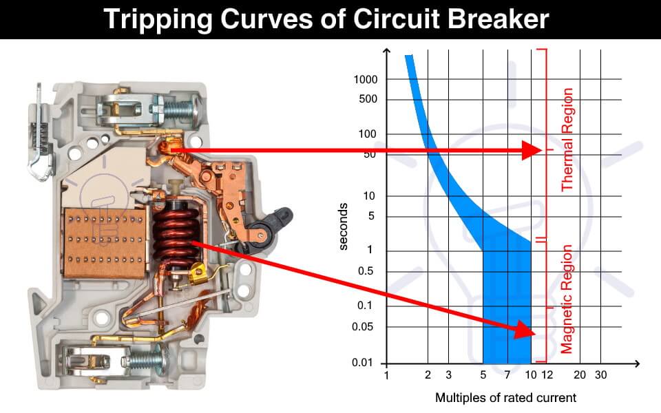
What is a Trip Curve?
A trip curve also known as a current time graph is a graphical representation of the response of a circuit breaker. It shows the current relationship with the tripping time of a protection device.
Why We Need Different Tripping Curves?
Circuit breakers are used for tripping the power supply as quickly as possible in case of overcurrent. But it should not trip so fast & unnecessary that it becomes a problem.
The overcurrent can happen under normal conditions such as the inrush current of a motor. Inrush current is the huge current draw during the starting of a motor that causes voltage dips in the main line. The circuit breaker should be able to tolerate the inrush current & it should provide some delay before tripping.
Therefore, the circuit breaker selected should not trip so fast that it creates a nuisance & it should not trip so late that it causes any damage. This is where the tripping characteristics of the circuit breakers come into play.
The tripping curve tells how fast a circuit breaker will trip at a specific current. The different tripping curves classify the circuit breakers into categories where each category is used for specific types of loads. It is essential to select a circuit breaker that provides the necessary overcurrent protection.
- Types of Circuit Breakers – Working and Applications
- Air Circuit Breaker (ACB): Construction, Operation, Types and Uses
How to read a Trip Curve?
The following figure shows a chart of a trip curve.
The horizontal X-axis represents the multiples of the current flowing through the circuit breaker. While the Y-axis represents the tripping time of the circuit breaker on a logarithmic scale.

The thermal region shows the response of the bimetallic contact trip unit during overcurrent. The curve shows that the circuit breaker’s tripping time reduces with an increase in the current. The first curve in the graph shows the response of a thermal trip unit.
While the magnetic region shows the response of the solenoid to fault current such as a short circuit current.
As seen from the graph, a circuit breaker does not have a fixed tripping time and we cannot predict an exact tripping point. It is because the tripping is affected by ambient conditions such as temperature. Think of it as a Schrödinger’s Cat area, we do not know when the tripping will occur unless the event happens.
Types of Circuit Breaker Based on Tripping Curves
The circuit breakers are classified into the following five types based on their tripping curves.

Such type of circuit breaker is designed to instantly trip when the operating current is 3 to 5 times its rated current. Their tripping time falls between 0.04 to 13 seconds. They are suitable for domestic applications where surges are very low such as lighting & resistive loads.

They are sensitive and must not be used in places where the normal surges keep on tripping it unnecessarily.
Type C circuit breaker trips instantly at current surges 5 to 10 times its rated current. its tripping time lies between 0.04 to 5 seconds. As they can tolerate higher surge currents, they are used in commercial applications such as the protection of small motors, transformers, etc.

Type D circuit breaker trips instantly when operating current reaches 10 to 20 times its rated current. Its tripping time is 0.04 to 3 seconds. Such circuit breakers can tolerate the high inrush current of large motors. Therefore, they are suitable for running heavy loads in industrial applications.

Such type of circuit breakers trips at 10 to 12 times its rated current with a tripping time of 0.04 to 5 seconds. These circuit breakers are also used for heavy inductive loads in industrial applications.

Type Z circuit breakers are the most sensitive circuit breaker that instantly trips when the operating current reaches 2 to 3 times its rated current. They are used for sensitive equipment that requires very low short circuit trip settings.

- Main Difference between Fuse and Circuit Breaker
- Difference Between MCB, MCCB, ELCB and RCB, RCD or RCCB Circuit Breakers
- How to Read MCB Nameplate Data printed on it?
- How to Find the Proper Size of Circuit Breaker? Breaker Calculator and Examples
- HVDC Circuit Breaker – Types, Working and Applications
- Can We Use AC Circuit Breaker for DC Circuit and Vice Versa?
- Electronic Circuit Breaker – Schematic and Working
- Smart WiFi Circuit Breaker – Construction, Installation and Working
- Why Circuit Breaker Capacity Was Rated in MVA and Now in kA and kV?
- How to Wire 120V and 240V Main Panel? Breaker Box Installation – US – NEC
- How to Wire Single-Phase, 230V Consumer Unit (Breaker Box) with RCD? IEC, UK and EU
This Post has been published by WWW.ELECTRICALTECHNOLOGY.ORG.
Electrical Technology
Related articles.

A Complete Guide About Solar Panel Installation. Step by Step Procedure with Calculation & Diagrams

How to Calculate the Battery Charging Time & Battery Charging Current – Example

Automatic UPS / Inverter Connection Diagram to the Home Panel Board

How to Find the Proper Size of Wire & Cable: Metric & Imperial Systems

Automatic Street Light Control Circuit using LDR & Transistor BC 547

Emergency LED Light Circuit – DP-716 Rechargeable 30 LED’s Lights Schematic
One comment.
Do we have to consider the tripping curves for DIY installation?
Leave a Reply Cancel reply
Your email address will not be published. Required fields are marked *

LV switchgear: functions and selection
- LV switchgear functions - Electrical protection
- LV switchgear functions - Isolation
- LV switchgear functions - Switchgear control
- Elementary switching devices
- Combined switchgear elements
- Switchgear selection
- Tabulated functional capabilities of LV switchgear
- Standards and description of circuit-breakers
Fundamental characteristics of a circuit-breaker
- Other characteristics of a circuit-breaker
- Selection of a circuit-breaker
- Coordination between circuit-breakers
- Selectivity MV/LV in a consumer’s substation
- Selectivity of Residual Current Devices (RCDs)
- Maintenance of low voltage switchgear
- 1 Rated operational voltage (Ue)
- 2 Rated current (In)
- 3 Frame-size rating
- 4 Overload relay trip-current setting (Irth or Ir)
- 5 Short-circuit relay trip-current setting (Im)
- 6 Circuit breaker suitable for isolation
- 7 Rated short-circuit breaking capacity (Icu or Icn)
- 9 Related technical guides
The fundamental characteristics of a circuit-breaker are:
- Its rated voltage Ue
- Its rated current In
- Its tripping-current-level adjustment ranges for overload protection (Ir [1] or Irth [1] ) and for short-circuit protection (Im) [1]
- Its short-circuit current breaking rating (Icu for industrial CBs; Icn for domestic-type CBs).
Rated operational voltage (Ue)
This is the voltage at which the circuit-breaker has been designed to operate, in normal (undisturbed) conditions.
Other values of voltage are also assigned to the circuit-breaker, corresponding to disturbed conditions as noted in Other characteristics of a circuit-breaker .
Rated current (In)
This is the maximum value of current that a circuit-breaker, fitted with a specified overcurrent tripping relay, can carry indefinitely at an ambient temperature stated by the manufacturer, without exceeding the specified temperature limits of the current carrying parts.
A circuit-breaker rated at In = 125 A for an ambient temperature of 40°C will be equipped with a suitably calibrated overcurrent tripping relay (set at 125 A). The same circuit-breaker can be used at higher values of ambient temperature however, if suitably “derated”. Thus, the circuit-breaker in an ambient temperature of 50°C could carry only 117 A indefinitely, or again, only 109 A at 60°C, while complying with the specified temperature limit.
Derating a circuit-breaker is achieved therefore, by reducing the trip-current setting of its overload relay, and marking the CB accordingly. The use of an electronic-type of tripping unit, designed to withstand high temperatures, allows circuit-breakers (derated as described) to operate at 60°C (or even at 70°C) ambient.
Note: In for circuit-breakers (in IEC 60947-2) is equal to Iu for switchgear generally, Iu being the rated uninterrupted current.
Frame-size rating
A circuit breaker which can be fitted with overcurrent tripping units of different current level-setting ranges, is assigned a rating which corresponds to the highest current-level-setting tripping unit that can be fitted.
A Compact NSX630N circuit-breaker can be equipped with 11 electronic trip units from 150 A to 630 A. The size of the circuit-breaker is 630A.
Overload relay trip-current setting (Irth or Ir)
Apart from small circuit-breakers which are very easily replaced, industrial circuit-breakers are equipped with removable, i.e. exchangeable, overcurrent-trip relays. Moreover, in order to adapt a circuit-breaker to the requirements of the circuit it controls, and to avoid the need to install over-sized cables, the trip relays are generally adjustable. The trip-current setting Ir or Irth (both designations are in common use) is the current above which the circuit-breaker will trip. It also represents the maximum current that the circuit-breaker can carry without tripping. That value must be greater than the maximum load current IB, but less than the maximum current permitted in the circuit Iz (see chapter Sizing and protection of conductors ).
The thermal-trip relays are generally adjustable from 0.7 to 1.0 times In, but when electronic devices are used for this duty, the adjustment range is greater; typically 0.4 to 1 times In.
(see Fig. H27 )
A NSX630N circuit-breaker equipped with a 400 A Micrologic 6.3E overcurrent trip relay, set at 0.9, will have a trip-current setting:
Ir = 400 x 0.9 = 360 A
Note: For circuit-breakers equipped with non-adjustable overcurrent-trip relays, Ir = In. Example: for iC60N 20 A circuit-breaker,
Ir = In = 20 A.
Short-circuit relay trip-current setting (Im)
Short-circuit tripping relays (instantaneous or slightly time-delayed) are intended to trip the circuit-breaker rapidly on the occurrence of high values of fault current. Their tripping threshold Im is:
- Either fixed by standards for domestic type CBs, e.g. IEC 60898, or,
- Indicated by the manufacturer for industrial type CBs according to related standards, notably IEC 60947-2.
For the latter circuit-breakers there exists a wide variety of tripping devices which allow a user to adapt the protective performance of the circuit-breaker to the particular requirements of a load (see Fig. H28 , Fig. H29 and Fig. H30 ).
- ^ 50 In in IEC 60898, which is considered to be unrealistically high by most European manufacturers (Schneider Electric = 10 to 14 In).
- ^ 1 2 For industrial use, IEC standards do not specify values. The above values are given only as being those in common use.
Circuit breaker suitable for isolation
A circuit-breaker is suitable for isolating a circuit if it fulfills all the conditions prescribed for a disconnector (at its rated voltage) in the relevant standard. In such a case it is referred to as a circuit-breaker-disconnector and marked on its front face with the symbol
All Acti 9, Compact NSX and Masterpact LV switchgear of Schneider Electric ranges are in this category.
Rated short-circuit breaking capacity (Icu or Icn)
The short-circuit current-breaking performance of a LV circuit-breaker is related (approximately) to the cos φ of the fault-current loop. Standard values for this relationship have been established in some standards
The short-circuit current-breaking rating of a CB is the highest (prospective) value of current that the CB is capable of breaking without being damaged. The value of current quoted in the standards is the rms value of the AC component of the fault current, i.e. the DC transient component (which is always present in the worst possible case of short-circuit) is assumed to be zero for calculating the standardized value. This rated value (Icu) for industrial CBs and (Icn) for domestic-type CBs is normally given in kA rms.
Icu (rated ultimate s.c. breaking capacity) and Ics (rated service s.c. breaking capacity) are defined in IEC 60947-2 together with a table relating Ics with Icu for different categories of utilization A (instantaneous tripping) and B (time-delayed tripping) as discussed in Other characteristics of a circuit-breaker .
Tests for proving the rated s.c. breaking capacities of CBs are governed by standards, and include:
- Operating sequences, comprising a succession of operations, i.e. closing and opening on short-circuit
- Current and voltage phase displacement. When the current is in phase with the supply voltage (cosφ for the circuit = 1), interruption of the current is easier than that at any other power factor. Breaking a current at low lagging values of cosφ is considerably more difficult to achieve; a zero power-factor circuit being (theoretically) the most onerous case.
In practice, all power-system short-circuit fault currents are (more or less) at lagging power factors, and standards are based on values commonly considered to be representative of the majority of power systems. In general, the greater the level of fault current (at a given voltage), the lower the power factor of the fault-current loop, for example, close to generators or large transformers.
Figure H31 below extracted from IEC 60947-2 relates standardized values of cos φ to industrial circuit-breakers according to their rated Icu.
- The dielectric withstand capability
- The disconnection (isolation) performance and
- The correct operation of the overload protection have not been impaired by the test.
- ^ 1 2 3 Current-level setting values which refer to the current-operated thermal and “instantaneous” magnetic tripping devices for over-load and short-circuit protection.
Related technical guides

Combine the benefits of selectivity and cascading to maximize power availability of your LV design at optimized cost.
- Chapter - LV switchgear: functions and selection
- Eig-content-pages
- previous page
About this wiki
The Electrical Installation Guide is now available here as a wiki (Electrical Installation Wiki). This wiki is a collaborative platform, brought to you by Schneider Electric: our experts are continuously improving its content, as they were doing for the guide. Collaboration to this wiki is also open to all.
- How to browse and search
- How to contribute
- Recent changes
- Special pages
- Random page
IMAGES
VIDEO
COMMENTS
50/51 and 50/51N relays. Overcurrent relays are the most commonly-used protective relay type. Time-overcurrent relays are available with various timing characteristics to coordinate with other protective devices and to protect specific equipment. Instantaneous overcurrent relays have no inherent time delay and are used for fast short-circuit ...
The thermal element acts as protection from overloading while the magnetic element is for protection from faults. This allows slow operation on overload and fast on fault. A typical time-current curve is shown in figure 6. Thermal Magnetic trip devices may be fixed or adjustable based on the ampere rating. Figure 6.
•Determine the characteristics, ratings, and settings of overcurrent protective devices •Ensure that the minimium, un-faulted load is ... Trip or clear on and to right of curve All devices should be considered at same voltage 18 . Short Time (i.e., motor starts/stops)
The Basics Of Overcurrent Protection (photo credit: @netceler via Twitter) There are three types of operating characteristics of overcurrent relays: Inverse-Time Protection. 1. Definite (instantaneous)-current protection. This relay is referred as definite (instantaneous) overcurrent relay.
Radial electrical system with time discrimination. Overcurrent relay protection is given at B, C, D and E, that is, at the infeed position of each part of the electrical power system. Each relay protection device comprises a definite-time delay overcurrent protection relay in which the trip of the current sensitive element starts the time delay ...
adjustable circuit breaker's inverse time characteristics. The position of the long time portion of the trip curve is normally referenced in seconds at 600 percent of the current setting (Ir). ... The direct-acting overcurrent trip devices may include ground trip elements. 41 - RATED MAXIMUM VOLTAGE: the rated maximum voltage of a circuit
Electromechanical 51 (time overcurrent) relays are more complicated in design, using a rotating metal "induction disk" to physically time the overcurrent event, and trip the circuit breaker only if the overcurrent condition persists long enough. A photograph of a General Electric time-overcurrent induction-disk relay appears here:
Among overcurrent protective devices used as protection against overcurrents, there are circuit breakers which, in case of fault, open the circuit based on their tripping characteristics and on the overcurrent value.. The circuit breaker is a mechanical switching device, capable of making, carrying, and breaking current under normal circuit conditions and also, making and carrying for a ...
Here's a list of different types of overcurrent relays and their application. Overload protection. Thermal Relays. Low-voltage distribution system. HRC Fuse, drop-out fuse. Instantaneous Overcurrent protection. Moving Iron type, Moving coil type, attracted armature type. Inverse time characteristics.
Overcurrent Relay Characteristics. Overcurrent time protection can have a directional or non-directional trip characteristic. The single-stage trip characteristic of non-directional, maximum-overcurrent time protection is shown in Figure 2 and functions as described above.
The characteristics of overcurrent relays are based on operating times typically governed by a time vs. current curve. There are three main types of overcurrent relay: (1) Instantaneous, (2) Time-Dependent (Definite time or inverse), and (3) Mixed (Definite time and Inverse). 1. Instantaneous relays have operating times usually less than 3 cycles.
and long time overcurrent trip characteristics of 600 V air circuit breakers. OVER- AND UNDERCURRENT RELAYS (see Table 7) are used where an indication of the varia-tion of a current between maximum and minimum limits is required. These relays do not have a time dial. The time charac-teristics are determined by the contact settings. TORQUE ...
A new adaptive protection approach for overcurrent relays using novel nonstandard current-voltage characteristics ... As a result, with extremely high currents, the OCR will trip quickly. According to the IEC 60255 ... Effect of nonstandard characteristics of overcurrent relay on protection coordination and maximizing overcurrent protection ...
The time for which the OL should pause before reacting will be different for various motors and applications is called the motor trip class. The most common trip classes are 5, 10, 20, and 30, which refer to the number of seconds for which the OL will allow this 600% current in-rush. Applications for each of these trip classes can be classified ...
1. Types of overcurrent system. Where a source of electrical energy feeds directly to a single load, a little complication in the circuit protection is required beyond the provision of an overcurrent device that is suitable in operating characteristics for the load in question, i.e. appropriate current setting possibly with a time-lag to permit harmless short time overloads to be supplied.
Overcurrent refers to an electrical condition in a circuit where the current flowing through the conductors exceeds the rated or designed current-carrying capacity of the components, such as wires, fuses, circuit breakers, and other protective devices. Overcurrent can occur due to various factors and can have different consequences, including ...
1SDC007400G0201. 1. Introduction. This White Paper is aimed at making easier the reading and the interpretation of the characteristic curves (trip curves, specific let-through energy curves and limitation curves) of the Molded-Case Circuit Breakers (MCCBs) and Low Volt-age Power Circuit Breakers (LVPCBs) manufactured by ABB SACE in compliance ...
The predetermined value of the current at which the relay starts operating by initiating a trip signal is known as its pick-up value. ... The time-current characteristics for these relays are steeper than that of very inverse overcurrent characteristics. They are required for fuse coordination and thermal protection of transformers, induction ...
The fault current should lag the voltage by 40-89.9 degrees depending on the line characteristics, voltage, and severity of the fault. ... If the fault current is larger than the overcurrent setting, the relay will trip. Directional overcurrent protection schemes were replaced with line impedance relays (21) to prevent a situation like this ...
3. Inverse Time Overcurrent Relays (IDMT Relay) In this type of relays, operating time is inversely changed with current. So, high current will operate overcurrent relay faster than lower ones. There are standard inverse, very inverse and extremely inverse types. Discrimination by both 'Time' and 'Current'.
A circuit breaker has two types of tripping unit i.e. thermal and magnetic tripping unit. Thermal Tripping Unit: the thermal tripping unit is used for protection against overloading. It uses a bi-metallic contact that bends with a change in temperature. The current flowing through the bimetallic strip heats up contact & trip the circuit breaker.
The thermal-trip relays are generally adjustable from 0.7 to 1.0 times In, but when electronic devices are used for this duty, the adjustment range is greater; typically 0.4 to 1 times In. Example (see Fig. H27) A NSX630N circuit-breaker equipped with a 400 A Micrologic 6.3E overcurrent trip relay, set at 0.9, will have a trip-current setting:
A NSX630N circuit breaker equipped with a 400 A Micrologic 6.3E overcurrent trip relay, set at 0.9, will have a trip-current setting: ... There are other characteristics of a circuit-breaker that are not mentioned in this article: rated insulation voltage, rated impulse-withstand voltage, rated short-time withstand current, rated making ...