
Travelling Wave Tube (TWT)
A travelling wave tube is a high power amplifier used for the amplification of microwave signals up to a wide range. It is a special type of vacuum tube that offers an operating frequency ranging between 300 MHz to 50 GHz .
Travelling wave tubes are non-resonant structures that offer continuous interaction of applied RF field with the electron beam over the entire length of the tube. Due to this reason, it provides wider operating bandwidth.
Content: Travelling Wave Tube
Basic concept.
- Construction
Need of Slow-Wave Structure
- Applications
Travelling wave tubes are abbreviated as TWT . It is majorly used in the amplification of RF signals. Basically a travelling wave tube is nothing but an elongated vacuum tube that allows the movement of electron beam inside it by the action of applied RF input.
The movement of an electron inside the tube permits the amplification of applied RF input. As it offers amplification to a wide range of frequency thus is considered more advantageous for microwave applications than other tubes.
It offers average power gain of around 60 dB . The output power lies in the range of few watts to several megawatts.
A travelling wave tube is basically of two types one is helix type and the other is coupled cavity. Here in this section, we will discuss the detailed construction and working of a helical travelling wave tube.
Construction of Travelling Wave Tube
The figure here shows the constructional structure of a TWT:

As we can see that the helical travelling wave tube consists of an electron gun and a slow-wave structure . The electron gun produces a narrow beam of the electron. A focusing plate is used that focuses the electron beam inside the tube.
A positive potential is provided to the coil (helix) with respect to the cathode terminal. While the collector is more positive than the coil (helix). In order to restrict beam spreading inside the tube. A dc magnetic field is applied between the travelling path by the help of magnets.
The signal which is needed to be amplified is provided at one of the ends of the helix, present adjacent to the electron gun. While the amplified signal is achieved at the opposite end of the helix.
In the figure, we can clearly see that attenuator is present along both the sides of the travelling wave tube. This is so because travelling wave amplifiers are high gain devices, so in case of poor load matching conditions, oscillations get build up inside the tube due to reflection.
Thus in order to restrict the generation of oscillations inside the tube attenuators are used.
Attenuators are basically formed by providing a metallic coating over the surface of the glass tube. Aquadag or Kanthal are majorly used for this.
It is to be noteworthy that a slow-wave structure is considered here, the reason is to maintain continuous interaction between the travelling wave and electron beam.
We know that the velocity of the electromagnetic wave is very much higher when compared with the phase velocity of the electron beam emitted by the electron gun.
Basically the RF wave applied at the input of TWT propagates with the speed of light (i.e., 3 * 10 8 m/s ). While the propagating velocity of the electron beam inside the tube is comparatively smaller than the velocity of RF wave.
If we try to somehow accelerate the velocity of the electron beam, then it can be accelerated only to a fraction of velocity of light. So it is better to reduce the velocity of the applied RF input in order to match the velocity of the electron beam.
Therefore, a slow-wave structure is used that causes a reduction in the phase velocity of the RF wave inside the TWT.
The slow-wave structures can be of different types like a single helix, double helix, zigzag line, corrugated, coupled-cavity or ring bar type etc.
A single helix slow-wave structure is formed by wounding a wire of element like tungsten and molybdenum in the form of a coil. The helical shape of the structure slows the velocity of the wave travelling along its axis to a fraction of about one-tenth of c.
This is so because due to the helical shape of the structure, the wave travels a much larger distance than the distance travelled by the beam inside the tube. So, in this way, the speed of wave propagation depends on the number of turns or diameter of the turns.
More specifically we can say that change in pitch can vary the speed of wave propagation inside the tube.
The equation given below shows the relation of phase velocity of the wave with the pitch of the helix:

: c = velocity of light (3 * 10 8 m/s)
V P = phase velocity in m/s
P = pitch of helix in m
d = diameter of the helix in m
Therefore, this causes continuous interaction between the RF input wave and the electron beam as the velocity of propagation of the two is not highly different. As such interaction is the basis of working of TWT thus slow-wave structures are used.
Working of Travelling Wave Tube
Till now we have discussed the complete constructional structure of TWT. Let us now understand how the signal gets amplified while travelling inside the tube.
The applied RF signal produces an electric field inside the tube. Due to the applied positive half, the moving electron beam experiences accelerative force. However, the negative half of the input applies a de-accelerative force on the moving electrons.
This is said to be velocity modulation because the electrons of the beam are experiencing different velocity inside the tube.
However, the slowly travelling wave inside the tube exhibits continuous interaction with the electron beam.
Due to the continuous interaction, the electrons moving with high velocity transfer their energy to the wave inside the tube and thus slow down. So with the rise in the amplitude of the wave, the velocity of electrons reduces and this causes bunching of electrons inside the tube.
The growing amplitude of the wave resultantly causes more bunching of electrons while reaching the end from the beginning. Thereby causing further amplification of the RF wave inside the tube.
More specifically we can say that forward progression of the field along the axis of the tube gives rise to amplification of the RF wave. Thus at the end of the tube an amplified signal is achieved.
The positive potential provided at the other end causes collection of electron bunch at the collector.
The magnetic field inside the tube restricts the spreading of the beam as the electrons possess repulsive nature.
However, as the TWT is a bidirectional device . Therefore, the reflected signal causes oscillations inside the tube. But as we have already discussed earlier that the presence of attenuators reduces the generation of oscillations due to reflected backwave.
Sometimes despite using attenuators, internal impedance terminals are used that puts less lossy effects on the forward signal.
Applications of TWT
- Travelling wave tubes are highly used in continuous wave radar systems.
- These amplifying tubes also find application in broadband receivers for RF amplification.
- TWT’s are also used to get high power output in satellite transponders.
So from the above discussion, we can conclude that no resonant structure is present in the interaction space. Thus provides amplification up to a wide bandwidth operating range.
However, the input and output coupling arrangements must be considered carefully as they limit the operating range.
Related Terms:
- Transmission Lines
- IMPATT Diode
- Backward Wave Oscillator
Leave a Comment Cancel Reply
Your email address will not be published. Required fields are marked *
- Microwave Engineering Tutorial
- Microwave Engineering - Home
- Introduction
- Transmission Lines
- Modes of Propagation
- Types of Transmission Lines
- Avalanche Transit Time Devices
- Microwave Devices
- E-Plane Tee
- H-Plane Tee
- E-H Plane Tee
- Rat-race Junction
- Directional Couplers
- Cavity Klystron
- Reflex Klystron
Travelling Wave Tube
- Measurement Devices
- Measurements
- Example Problems
- Microwave Engineering Resources
- Quick Guide
- Microwave Engineering - Resources
- Microwave Engineering - Discussion
- Selected Reading
- UPSC IAS Exams Notes
- Developer's Best Practices
- Questions and Answers
- Effective Resume Writing
- HR Interview Questions
- Computer Glossary
Travelling wave tubes are broadband microwave devices which have no cavity resonators like Klystrons. Amplification is done through the prolonged interaction between an electron beam and Radio Frequency (RF) field.
Construction of Travelling Wave Tube
Travelling wave tube is a cylindrical structure which contains an electron gun from a cathode tube. It has anode plates, helix and a collector. RF input is sent to one end of the helix and the output is drawn from the other end of the helix.
An electron gun focusses an electron beam with the velocity of light. A magnetic field guides the beam to focus, without scattering. The RF field also propagates with the velocity of light which is retarded by a helix. Helix acts as a slow wave structure. Applied RF field propagated in helix, produces an electric field at the center of the helix.
The resultant electric field due to applied RF signal, travels with the velocity of light multiplied by the ratio of helix pitch to helix circumference. The velocity of electron beam, travelling through the helix, induces energy to the RF waves on the helix.
The following figure explains the constructional features of a travelling wave tube.

Thus, the amplified output is obtained at the output of TWT. The axial phase velocity $V_p$ is represented as
$$V_p = V_c \left ( {Pitch}/{2\pi r} \right )$$
Where r is the radius of the helix. As the helix provides least change in $V_p$ phase velocity, it is preferred over other slow wave structures for TWT. In TWT, the electron gun focuses the electron beam, in the gap between the anode plates, to the helix, which is then collected at the collector. The following figure explains the electrode arrangements in a travelling wave tube.

Operation of Travelling Wave Tube
The anode plates, when at zero potential, which means when the axial electric field is at a node, the electron beam velocity remains unaffected. When the wave on the axial electric field is at positive antinode, the electron from the electron beam moves in the opposite direction. This electron being accelerated, tries to catch up with the late electron, which encounters the node of the RF axial field.
At the point, where the RF axial field is at negative antinode, the electron referred earlier, tries to overtake due to the negative field effect. The electrons receive modulated velocity. As a cumulative result, a second wave is induced in the helix. The output becomes larger than the input and results in amplification.
Applications of Travelling Wave Tube
There are many applications of a travelling wave tube.
TWT is used in microwave receivers as a low noise RF amplifier.
TWTs are also used in wide-band communication links and co-axial cables as repeater amplifiers or intermediate amplifiers to amplify low signals.
TWTs have a long tube life, due to which they are used as power output tubes in communication satellites.
Continuous wave high power TWTs are used in Troposcatter links, because of large power and large bandwidths, to scatter to large distances.
TWTs are used in high power pulsed radars and ground based radars.
Search form
Travelling wave tubes: timeless precision that goes a long way.
Share this article
Do you know what a travelling wave tube is, what it does and how it is made? A new video highlights the innovation, craft and precision required in this technological marvel, refined by world-leader Thales over many decades.
In an age propped up by quintillions of solid-state devices - the semiconductors and microprocessor chips in all our consumer electronics - should you even care about vacuum tubes? Yes is the short answer, because without these intricate objects amplifying the signals coming from satellites and radars, many of the tools we rely on today to travel, to work and for our leisure would not be possible.
Put simply, the tube is an integral part of these transmitters, where the input signal is often very weak and the output needs to be high power. Solid-state devices – which need large amounts of energy to function and to keep them cool - cannot perform this role, especially given the immense distances the signals need to travel, the length of time the transmitters need to function and the amount of power available.
Revolutionising communications
The story of these tubes – known as travelling wave tubes (TWTs) - goes back nearly 80 years, to research performed by Rudolf Kompfner in a British Admiralty radar laboratory during World War II. His invention centred on a vacuum electron tube that could amplify wide-band microwave signals to hugely increase the range of wireless communications.
Shortly after the war ended, Thales – then known as CSF – had set up its own specialised TWT R&D and production centres, producing radars and communication systems that would help launch the space industry in the 1970s. Today, Thales is the world's leading supplier of traveling wave tubes for space, defence and satcom markets.
Most data sent by satellites today uses a Thales amplifier. Many thousands of Thales TWTs have been launched into orbit since 1974 providing over 900 million hours of operation. They are even helping to transmit data from the Exo Mars mission, and to understand worlds at the very edge of our solar system through the New Horizons mission. You can see details on all the missions our TWTs are involved with here .
Over 60 individual skills to build one tube
For over 70 years, the women and men of Thales have been pushing the boundaries of physics to connect people through exceptional products that are designed to last in even the most severe environments. At our sites in Vélizy, Thonon and Ulm, engineers, technicians and operators share unrivalled expertise split over more than 60 individual skills. Each component is built and tested with an extreme precision because the success of each space mission – and the communications we all rely on – depend on our tubes.
See how all the elements are put together, and how the tube functions in the video below.

Traveling Wave Tubes
Traveling Wave Tubes are vacuum-based devices that amplify microwave signals with high gain and wide bandwidth, used in radar, communication, and satellites.

Traveling Wave Tubes: A Comprehensive Introduction
What are traveling wave tubes.
Traveling Wave Tubes (TWTs) are specialized vacuum tubes that are commonly used as high-power, wideband, and linear amplifiers for microwave frequency signals. Invented by Rudolf Kompfner in 1943, TWTs have since become an essential component in radar, communication systems, and satellite technology, enabling the transmission of signals over long distances with minimal loss and distortion.
How do Traveling Wave Tubes work?
At the core of a TWT is a helix, a coiled wire that acts as a slow-wave structure. The helix is housed in an electron beam-controlling cylindrical tube, which is encased within a vacuum. The electron beam is generated by an electron gun, and its velocity is controlled by an external magnetic field.
When a microwave signal enters the TWT, it travels along the helix, interacting with the electron beam. The electrons, which move at a similar velocity to the microwave signal, transfer energy to the signal, amplifying it. As the microwave signal continues to travel along the helix, it accumulates energy, resulting in significant amplification by the time it exits the TWT.
Key Components of a Traveling Wave Tube
- Electron Gun: Generates the electron beam that interacts with the microwave signal to amplify it.
- Helix: A slow-wave structure that enables the interaction between the microwave signal and the electron beam. The helix is critical to the performance of a TWT, as it determines the frequency range and gain of the device.
- Collector: Captures the spent electron beam after it has transferred its energy to the microwave signal. The collector converts the remaining kinetic energy of the electrons into heat, which is then dissipated by a cooling system.
- Magnetic Field: An external magnetic field is used to control the velocity and trajectory of the electron beam, ensuring that it remains focused and properly aligned with the helix.
- Vacuum Tube: The TWT operates within a vacuum to minimize energy loss due to interactions with air molecules and to prevent the formation of plasma, which could damage the device.
Advantages of Traveling Wave Tubes
Traveling Wave Tubes offer several advantages over other microwave amplification technologies, such as solid-state amplifiers and klystrons. Some of the key benefits include:
- Wide Frequency Range: TWTs can operate over a broad range of frequencies, typically from 0.3 GHz to 50 GHz or higher. This makes them suitable for a wide variety of applications, from radar systems to satellite communications.
- High Gain: TWTs can achieve high gain, often in the range of 40 to 60 dB or more, enabling the amplification of weak signals for transmission over long distances.
- Wide Bandwidth: The bandwidth of a TWT can be several gigahertz, allowing for the simultaneous amplification of multiple signals or channels.
Disadvantages of Traveling Wave Tubes
Despite their numerous advantages, TWTs also have some drawbacks that must be considered when selecting an appropriate microwave amplifier for a specific application. These include:
- Complexity and Cost: TWTs are complex devices with many components, making them more expensive to manufacture and maintain compared to some solid-state amplifiers.
- Size and Weight: The vacuum tube and cooling systems required for TWTs can result in larger and heavier devices, which may not be suitable for all applications, especially in space-constrained environments.
- Lower Efficiency: TWTs tend to have lower power efficiency compared to solid-state amplifiers, which can lead to higher power consumption and increased cooling requirements.
Applications of Traveling Wave Tubes
Traveling Wave Tubes have been widely adopted in various industries and applications due to their unique capabilities. Some of the most common uses for TWTs include:
- Radar Systems: TWTs are used in radar systems for both military and civilian purposes, providing high-power amplification for signals used in air traffic control, weather forecasting, and defense applications.
- Communications: TWTs play a crucial role in satellite communications, enabling the transmission of signals over long distances with minimal loss and distortion. They are also used in terrestrial microwave communication links and undersea cable systems.
- Electronic Warfare: TWTs are employed in electronic warfare systems, such as electronic countermeasures (ECM) and electronic support measures (ESM), to amplify signals for jamming or intercepting enemy communications and radar signals.
- Particle Accelerators: TWTs are utilized in some particle accelerator facilities to provide high-power microwave signals required for accelerating charged particles to high velocities.
Future of Traveling Wave Tubes
Despite the ongoing development and adoption of solid-state amplifiers, TWTs continue to be relevant in many applications due to their unique capabilities. Research efforts are being directed towards improving the efficiency, size, and weight of TWTs to enhance their competitiveness with solid-state technologies.
One promising area of research involves the development of new materials and manufacturing techniques for TWT components, such as advanced helix structures and electron guns. These innovations could result in significant performance improvements, making TWTs even more attractive for a wide range of applications.
Traveling Wave Tubes remain an essential technology for amplifying microwave signals in a variety of industries and applications, from radar systems to satellite communications. Their wide frequency range, high gain, and wide bandwidth make them indispensable for many critical systems. Although solid-state amplifiers have gained traction in recent years, ongoing research and development in TWT technology ensure that they will continue to play a vital role in the future of microwave signal amplification.
Related Posts:

The primary purpose of this project is to help the public to learn some exciting and important information about electricity and magnetism.
Privacy Policy
Our Website follows all legal requirements to protect your privacy. Visit our Privacy Policy page.
The Cookies Statement is part of our Privacy Policy.
Editorial note
The information contained on this website is for general information purposes only. This website does not use any proprietary data. Visit our Editorial note.
Copyright Notice
It’s simple:
1) You may use almost everything for non-commercial and educational use.
2) You may not distribute or commercially exploit the content, especially on another website.
Traveling Wave Tubes: Modern Devices and Contemporary Applications
From its conception in 1943 by Dr. Rudolf Kompfner in England, 1 and later its development by Kompfner and John R. Pierce at the Bell Laboratories in the United States, 2 the travelling wave tube (TWT) has become the microwave amplifier of choice for many commercial and military systems. Originally developed for communication, these devices have become fundamental to many military applications, including radar, electronic counter measures (ECM) and electronic warfare (EW) systems.
In simple terms all types of TWTs consist of an electron gun, a slow wave structure, magnetic focussing system, RF input and output couplers, and a collector. With operating voltages applied, the electron gun (containing an emitter) produces an electron beam, which is injected into the slow wave structure (SWS).
The magnetic focussing system constrains the electron beam, allowing it to travel longitudinally down the centre of the slow wave structure.
RF power of the appropriate frequency is injected through the input coupler onto the slow wave structure. The electron beam and the RF signal travel down the structure at similar speeds and an interaction between the two results in an energy transfer from the electron beam into the electromagnetic wave, thus achieving an amplification in the RF signal. The collector at the opposite end of the device to the electron gun is designed to collect the spent electron beam and dissipate the remaining energy efficiently.
TWT Technology
Developments in material and manufacturing technologies over the past 50 years have aided the advancement of TWT capabilities. Improvements in high purity vacuum-compatible materials such as nickel/copper alloys and pure oxygen-free, high-conductivity (OFHC) copper have been a major contributor to improvements in both life and reliability.
Advances in thermionic cathode technology, resulting in increased operating life, and the development of high-energy product magnetic materials such as Samarium Cobalt, have enabled the reduction in size of magnetic circuits. The use of computer controlled processing systems and component-manufacturing machines have seen achievable tolerances reduce by an order of magnitude, along with a considerable reduction in unit cost.
Numerous structure designs have been conceived since its original conception, offering various advantages to different applications. Ervin Nalos’s paper, first published in the December 1959 issue of Microwave Journal (reprinted this month), focused primarily on high power travelling wave tubes. 3 Other circuit types were discussed, including the simple helix, ring-bar and bifilar, demonstrating the considerable understanding and capability of different slow wave structures 50 years ago.
The major constraints to higher performance were materials technology, processing techniques and manufacturing capabilities. The 1959 paper discusses the simple helix, having the capability of continuous wave (CW) powers as high as 10 W at X-band. Today CW helix TWTs have achieved output power levels of several kilowatts at X-band, a considerable achievement, largely due to current material technologies and automated manufacturing processes.
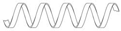
Figure 1 Simple helix slow wave structure (top) and photograph of a tungsten helix structure (bottom).
The ‘simple’ helix continues to be the most commonly used SWS in TWTs since its inception by Kompfner. In its simplest form, a wire or tape wound in the form of a helix, it exhibits the greatest potential of all SWSs, in terms of dispersion control and thus greatest operating bandwidth. Performance characteristics can be controlled through the design of simple and complex pitch tapering, to enhance both narrow and broadband operation, optimising gain, power and efficiency. Figure 1 shows both a sketch of a simple helix structure and a photograph of a tungsten tape helix.
Dispersion characteristics can be controlled through design of helix supports, in terms of material choice and cross-sectional shape and electrically conductive dispersive vanes. Vanes offer the greatest opportunity for dispersion control and are commonly utilized within broadband TWTs of greater than an octave bandwidth.
Bifilar Contra-wound and Ring-bar TWTS
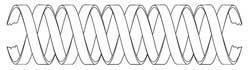
Figure 2 SBifilar contra-wound (top) and ring-bar (bottom) slow wave structures.
Variants on the simple helix include the bifilar helix (made up of two contra-wound helices of equal but reversed pitch), the ring-bar and the ring-loop structure. Sketches of both bifilar and ring-bar structures can be seen in Figure 2 . These types of structures enable higher power handling through both thermal capability and higher voltage operation without giving rise to backward wave oscillation (BWO), a major constraint in simple helix structures. The downsides to these types of structures (in relation to the simple helix) are the limitation of bandwidth due to the high dispersion characteristics of the SWS and the increased complexity in manufacture, which directly impacts the cost.
Coupled Cavity TWTs
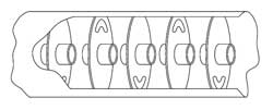
Figure 3 Slotted (top) and clover-leaf (bottom) coupled cavity slow wave structures.
The feature that distinguishes the coupled cavity TWT from other types is the SWS, which consists of a series of cavities, is coupled by slots. The benefits of this are that the cavities can be designed to operate with high voltage electron beams enabling peak output powers of 10s to 100s of kilowatts, with high average powers. The space harmonic coupled cavity circuit, favoured by most users because of the high (up to 20 percent) instantaneous bandwidth achievable, is particularly suited to integration of periodic permanent magnetic (PPM) focussing. The result is a very compact device that is used in mobile radar systems. Very high average power and CW coupled cavity TWTs are available but these utilise solenoid focussing, which requires significant electrical power and weighs more than PPM focussed devices. Figure 3 shows two of the more commonly used coupled cavity type structures: slotted and clover-leaf.
Cathode Technology
Developments in the field of emitters, the electron source of travelling wave tubes, have enabled the development of devices capable of 10s and even 100s of thousands of hours of life. Fifty years ago the electron sources used in vacuum devices, including the early TWTs, would have been of the oxide-coated type emitter, restricted to pulsed or low current density CW applications, ideally suited to high-power pulsed devices, like the coupled cavity TWT, used for radar-type applications.
Today, with advances in cathode technology, materials and processing, a range of impregnated tungsten matrix cathodes are the cathode of choice. Capable of considerably higher mean currents, operating CW at high current densities (> 20 A/cm 2 ), the coated tungsten matrix (M-type) cathode is the most commonly used. Other advantages over the oxide cathode include higher resistance to poisoning, increased life and improved manufacturing tolerances because of the machined emitting surface.
In addition to this, coupled with a potted heater assembly, cathodes have been manufactured to survive and function under the most severe vibration and shock levels.
Work continues towards making advances in cathode design and manufacture. Developments include mixed-matrix and reservoir cathodes, and more recently the field emitting cold cathode. 4 Although in its infancy, recent research has produced samples nearing the capabilities required for a TWT electron source.
TWT Design and Validation
The introduction of computer modelling and its advances over the past three decades have had a marked impact on the vacuum electronics industry, taking design from long-hand calculations (sometimes only comprehendible to the most advanced mathematicians) to user-friendly computer simulation of all aspects (electronic, mechanical, thermal) of the device design.
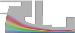
Figure 4 OPERA 2D finite element software-electron gun model.
3-D electron beam simulation programmes enable accurate simulation of beam entry, focussing systems and collection. Figure 4 shows a plot from an electron gun model, using OPERA 2D. Together with the constant advances in computing power, designs can be realised in hours or even minutes, and once validated, the latest software is capable of previously unprecedented levels of accuracy.
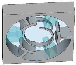
Figure 5 Microwave Studio parametric model of a helix SWS.
Advances in Particle in Cell (PIC) and parametric codes, combined with complex optimisers, enables accurate simulation of the interaction between electron beam and the slow wave structure. Increases in computing power have enabled the simulation of complex slow wave structures and complete RF circuits. Figure 5 is a cross-section of a helix SWS, showing dielectric helix support rods and dispersion vanes, typically used in broadband helix TWTs.
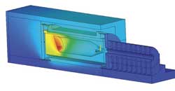
Figure 6 3D thermal simulation model of TWT collector assembly.
In addition to the advances in electrical design enabled by new codes and improved processing speeds, commercially available codes can be utilised for thermal and mechanical stress analysis. Thermal analysis of TWT collectors enables improved thermal management of new designs. Figure 6 shows a simple thermal model of a single stage collector. The modern-day designer now has a complete package of modelling and simulation codes that, when fully validated with real device data, enable a right-first-time design approach significantly reducing development times and costs.
Present State of the TWT Art
TWT production is limited to a handful of manufacturers throughout the world; major suppliers include CPI, L-3 and Teledyne in the US, e2v, Thales and TMD in Europe, NEC in Japan, and several developing manufacturers in both India and China.
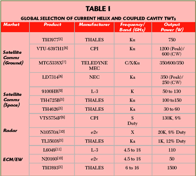
Table 1 Global Selection of Current Helix and Coupled Cavity TWTs
Determining the current state of the art is difficult; many government-funded programmes restrict the publication of data and commercial confidentiality is high due to the competitive markets. Table 1 shows a cross-section of products from various manufacturers, giving a broad view of current capabilities.
Satellite Communications (Ground-based)
Low cost, high reliability and high linearity are key in this commercially competitive market. Offerings are available from all the major manufacturers, whether it is earth stations, Satellite News Gathering (SNG) mobile systems, network hubs or small lightweight flyaway pack systems. Demands for bandwidth are forcing the move towards higher frequencies (Ka-band) and the onset of digital broadcasting requires higher powers.
Notable performance advances have been achieved by NEC and L-3 in the development of Ka-band helix TWTs for this market, with CW power levels as high as 500 W. Another growth area is in small lightweight amplifiers used in flyaway and hand portable systems. Reductions in luggage weight, by most airlines around the world, has forced demand for these systems to become smaller and lighter. In a market where solid state amplifiers and travelling wave tube amplifiers (TWTA) compete head to head, e2v has launched a range of TWTAs (StellarMini™) that are the smallest and lightest currently available.
Advances in multi-octave TWTs developed originally for military applications has lead to opportunities in multi-band TWTAs for both commercial and military communications. Dual- and tri-band devices have been developed by Teledyne, CPI and e2v.
Satellite Communications (Space)
Key attributes of the space TWT include long life (mission life greater than 20 years), high reliability, low power consumption (high efficiency) and low mass. The majority of all TWTs in space have been manufactured by Thales (France) or L-3 Electron Technologies Inc. (US; formerly Boeing/Hughes) with developments progressing at CEERI (India).
Future demand is moving up in frequency as advances in solid state technology capture the low frequency end of the operating spectrum (up to Ku-band) and the overcrowding of traditional bands forces the need for greater bandwidth utilization. The number of satellites being launched at Ka-band is growing fast and is set to continue.
Traditionally the realm of high peak power helix and coupled cavity TWTs, the development of active phased-array radar has seen a significant shift away from vacuum devices towards solid state technology, more suited to compact packaging required in an array system.
Although as requirements become more demanding, requiring higher efficiency, lower thermal dissipation and greater reliability, customers of microwave amplifiers are turning back to TWTs as the preferred option. Over the past three decades TWT reliability has increased considerably; space TWTs have achieved MTBFs of six million hours with efficiencies reaching 50 percent, which makes the TWT a viable alternative to solid-state amplifiers (SSA). Advances in mini TWT technology, driven by airborne towed decoys and MPMs, has lead to compact high efficiency devices ideally suited to phased-array and Synthetic Aperture Radar (SAR) applications.
The largest market for the helix TWT is in ECM and EW applications, which has seen tens of thousands of devices built into expendable decoy systems and ECM pods around the world. The demands on devices tend to be a combination of those for all other applications, with the added complexity of operation over multi-octave bandwidths. Current demands are for greater bandwidth and higher efficiency in smaller lighter weight packages that are able to operate over extreme temperature ranges and high altitudes. With the growth of unmanned air vehicle (UAV) applications, the military business for TWTs continues to grow.
Over the past decade, the likes of L-3, CPI, Thales and e2v have developed ranges of mini TWTs, predominantly for airborne applications with bandwidths of greater than 2 octaves covering 4.5 to 18 GHz and power levels now exceeding 100 W CW across the full band. Devices have been proven to survive and operate at temperatures ranging from –55° to > 150°C, altitude > 70 kft and shock levels in excess of 500 G.
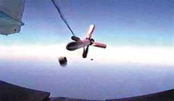
Figure 7 Deployed fibre optic towed decoy.
Utilization of multi-stage depressed collectors has seen mid-band efficiencies top 50 percent, resulting in reduced thermal footprints and prime power requirements. CPI 12 has, over the past two decades, delivered many thousands of mini TWTs into the Raytheon 12 Goleta ALE-50 towed decoy programme, which is a notable achievement. Figure 7 shows a typical fibre optic towed decoy (FOTD) TWT platform being deployed.
Advances continue to be made at higher frequencies covering the 18 to 40 GHz band for countering and jamming new threats. With continually changing and advancing threats, plus the upgrades to existing systems, demands on the microwave amplifiers in this market are increasing, continuing to enhance efficiency and expand bandwidth will be necessary to keep ahead of the advancing SSA sector and meet the expectations of customers.
Status of Coupled Cavity TWTs
Many modern radar systems, including new developments, continue to use coupled cavity TWTs. This is because, contrary to popular opinion, coupled cavity TWTs are often more robust, long-lived, reliable and efficient than the solid state alternative. Coupled cavity TWTs currently manufactured cover the frequency ranges from D-band up to M-band. Instantaneous bandwidth of 10 percent is required for most applications, but various techniques have been employed to increase this to 20 percent (normally compromising efficiency or power considerations).
The conventional manufacturing technique for coupled cavity TWTs employs individual cavities and coupling plates brazed together. At Ka-band and above, this technique becomes very expensive, as the machining tolerances become extremely tight.
Alternative methods of production for high frequency TWTs have been investigated, with the ladder structure used by CPI being the most popular. Modern computer aided design techniques have been used to redesign existing coupled cavity TWT designs; the result of this has been much higher manufacturing reproducibility, and hence yields. 13
New radar transmitter specifications continue to demand more from the TWT designer; the areas of particular interest are higher mean power, faster warm-up time and higher efficiency. The use of computer aided design tools to investigate these areas has been successfully employed. Notably, e2v has developed and built RF circuits for high mean power that overcome the natural limitation of heat being conducted through iron pole pieces. 14 Other manufacturers have increased mean power by improving the electron beam confinement under RF conditions. There is no reason why both techniques cannot be combined to produce coupled cavity TWTs of higher mean power capability.
Future Developments
Figure 8 Frequency and power capabilities of present amplifier technologies.
With the recent development of compound semiconductors into the power amplification domain, a number of power applications have now migrated from tube-based to solid state amplification. This is especially true of sub-kilowatt, narrow-band requirements, with recent developments in Silicon Carbide (SiC) and Gallium Nitride (GaN) extending these devices into multiple-kilowatt capability, to frequencies around 10 GHz and above. 15 Figure 8 shows the current solid-state and vacuum tube landscape, with respect to frequency and power.
As solid-state devices increase in capability, more applications will migrate from a tube to a transistor embodiment. However, for the present it is clear that travelling wave tubes continue to offer a compact and efficient amplifier solution, particularly under harsh operating environments. TWT amplifiers can also span a broad frequency bandwidth, approaching three octaves of coverage from a single tube.
Future Direction for TWTs
The future remains bright for TWTs, albeit in a tougher and more competitive market place. The continued progress of solid-state amplifiers will eat into the edges of the TWT domain, but there will remain to be requirements for the amplification of microwaves beyond the present capabilities of solid-state.
For systems with limitations on size, weight, power dissipation and consumption, there are, and will continue to be, numerous applications for vacuum electronic devices (VED). Higher power levels and higher frequencies are areas where tubes have no equal. The continued advances in VED technology will sustain growth.
In the commercial market, High Definition Television (HDTV) and the onset of the digital age are demanding higher powers and higher frequencies. These are major opportunity areas for the TWT.
The defence business worldwide continues to grow, upgrades to existing systems and new platforms, such as UAVs, require higher efficiencies, smaller lighter payload packages and improved reliability. Higher definition radar systems such as SARs and phased-array radar offer opportunities for small, lightweight, high-efficiency devices. Also, government and defence funding is being made available to the industry to continue developing products for the future. An area of considerable interest at present is in the terahertz and sub mm-wave frequency regimes. Research and development in this area include CAD design of MEMS type structures, manufacturability, detection techniques and prototype manufacture. Programmes are as yet undefined but potential uses include UAV SAR for tactical targeting and terrain avoidance and security imaging. 16
Acknowledgments
Inputs on TWT product history and technology development have been provided by Alan Griggs (e2v principal TWT engineer) and Ian Milsom (e2v cathode development and test manager). The overview of current power amplifier technology was compiled by Dr. Cliff Weatherup (e2v strategic technology manager) and Dr. Trevor Cross (e2v chief technology officer). Product and application photographs were provided by Andy Bennett (e2v marketing).
1. R. Kompfner, Travelling Wave Electronic Tube , US Patent no. 2630544, Filed 20th March 1948, Issued 3rd March 1953. 2. J.R. Pierce, “Travelling-wave Tubes,” Proc. IRE , Vol. 35, No. 2, February 1947, pp. 108-111 . 3. E.J. Nalos, “Present State of Art in High Power Travelling-wave Tubes: Part I,” Microwave Journal , Vol. 2, No. 12, December 1959, pp. 31-38. 4. D.R. Wahley, et al., “Operation of a Low Voltage High-transconductance Field Emitter Array TWT,” Proc. IEEE Vacuum Electronics Conference , April 22-24, 2008, pp. 78-79. 5. Product data from Thales web site: http://components-subsystems.thales-catalogue.com . 6. Product data from CPI, Microwave Power Products Division web site: http://www.cpii.com/product.cfm/1/19/65 . 7. Product data from Teledyne MEC web site: http://www.teledyne-mec.com/products/productCatalog.aspx . 8. Product data from NEC Microwave Tube web site: http://www.nec-mwt.com/english/products/twt/seihin/index.html . 9. Product data from L-3 Electron Technologies Inc. web site: http://www.l-3com.com/eti/product_lines_space_twt.htm . 10. Product Data from e2v. 11. Product Data from L-3, Electron Devices web site: http://www.l-3com.com/edd/products_mini_tubes.htm . 12. ALE-50 Contract reference, Business Journal, September 19, 2007, http://www.bizjournals.com/sanjose/stories/2007/09/17/daily44.html?ana=from_rss . 13. C. Ar, A.V. Piring and P. Tibbs, “F-Programs TWT Design Upgrades,” Proc. IEEE Vacuum Electronics Conference , April 27-29, 2004, pp. 20-21. 14. A. Griggs, “A New Coupled Cavity Circuit for High Mean Power Travelling-wave-Tubes,” IEEE Transactions on Electron Devices , Vol. 38, No. 8, August 1991, pp. 1952-1957. 15. R. Trew, “Wide Bandgap Semiconductor Transistors for Microwave Power Amplifiers,” IEEE Microwave Magazine , Vol. 1, No. 1, March 2000. 16. M.J. Rosker and H.B. Wallace, “Vacuum Electronics and the World Above 100 GHz,” Proc. IEEE Vacuum Electronics Conference , April 22-24, 2008, pp. 5-7.

Report Abusive Comment
Restricted Content
You must have JavaScript enabled to enjoy a limited number of articles over the next 7 days.
- Relay Latching Circuit: How to Design
- Multi-Switch Relay Control with EX-OR Gates
- Mic Preamp Schematic: Elevate Your DIY Audio Projects
- Simple Intruder Alarm Circuit
- Exploring the ICL8038: Building an Audio Function Generator Circuit
Engineering Projects
Projects for Engineering Students
- Electronic Tutorial
Traveling Wave Tube | Construction | Operation
The traveling wave tube (TWT) is a high-gain, low-noise, wide-bandwidth microwave amplifier . Traveling Wave Tube are capable of gains of 40 dB or more, with bandwidths of over an octave. (A bandwidth of one octave is one in which the upper frequency is twice the lower frequency.) TWTs have been designed for frequencies as low as 300 MHz and as high as 150 GHz and continuous outputs to 5 kW. Their wide-bandwidth and low-noise characteristics make them ideal for use as RF and medium-power amplifiers in microwave and electronic countermeasure equipment. They are widely used as the power output stage in orbiting satellites.
Construction of Traveling Wave Tube
Figure 1 is a pictorial diagram of a traveling wave tube. The electron gun produces a stream of electrons that are focused into a narrow beam by an axial magnetic field . The field is produced by a permanent magnet or electromagnet (not shown) that surrounds the helix portion of the tube. The narrow beam is accelerated, as it passes through the helix, by a high potential on the helix and collector.
The beam in a TWT is continually interacting with a RF electric field propagating along an external circuit surrounding the beam. To obtain amplification, the TWT must propagate a wave whose phase velocity is nearly synchronous with the do velocity of the electron beam. It is difficult to accelerate the beam to greater than about one-fifth the velocity of light. The forward velocity of the RF field propagating along the helix is slowed to nearly that of the beam due to its travel along the helix. Changing the pitch changes the speed of the RF field.

The electron beam is focused and constrained to flow along the axis of the helix. The longitudinal components of the input signal’s RF electric field, along the axis of the helix or slow wave structure, continually interact with the electron beam to provide the gain mechanism of TWTs. This interaction mechanism is pictured in Figure 2. This figure illustrates the RF electric field of the input signal, propagating along the helix, infringing into the region occupied by the electron beam.
Consider first the case where the electron velocity is exactly synchronous with the RF signal passing through the helix. Here, the electrons experience a steady dc electric force that tends to bunch them around position A and de-bunch them around position B in Figure 2. This action is due to the accelerating and decelerating electric fields. In this case, as many electrons are accelerated as are decelerated; hence, there is no net energy transfer between the beam and the RF electric field. To achieve amplification, the electron beam is adjusted to travel slightly faster (by increasing the anode voltage) than the RF electric field propagating along the helix. The bunching and debunching mechanisms just discussed are still at work, but the bunches now move slightly ahead of the fields on the helix. Under these conditions, more electrons are in the decelerating field to the right of A than in the accelerating field to the right of B. Since more electrons are decelerated than are accelerated, the energy balance is no longer maintained. Thus, energy transfers from the beam to the RF field, and the field grows and amplification occurs.

Fields may propagate in either direction along the helix. This leads to the possibility of oscillation due to reflections back along the helix. This tendency is minimized by placing resistive materials near the input end of the slow-wave structure. This resistance may take the form of a lossy wire attenuator (Figure 1) or a graphite coating placed on insulators adjacent to the helix. Such lossy sections completely absorb any backward traveling wave. The forward wave is also absorbed to a great extent, but the signal is carried past the attenuator by the bunches of electrons. These bunches are not affected by the attenuator and, therefore, reinstitute the signal on the helix, after they have passed the attenuator.
The traveling wave tube has also found application as a microwave mixer. By virtue of its wide bandwidth, the TWT can accommodate the frequencies generated by the heterodyning process (provided, of course, that the frequencies have been chosen to be within the range of the tube). The desired frequency is selected by the use of a filter on the output of the helix. A TWT mixer has the added advantage of providing gain as well as providing mixer action.
A TWT may be modulated by applying the modulating signal to a modulator grid. The modulator grid may be used to turn the electron beam on and off, as in pulsed microwave applications, or to control the density of the beam and its ability to transfer energy to the traveling wave. Thus, the grid may be used to amplitude-modulate the output. The TWT offers wideband performance with high-power outputs of up to 150 GHz. TWTs are widely used in wideband communications repeater links. They offer low-noise performance and high-power gains. Their high reliability dictates their use as power amplifiers in communications satellites, where a lifetime in excess of 10 years can be expected.
Traveling Wave Tube Oscillator
A forward wave, traveling wave tube may be constructed to serve as a microwave oscillator. Physically, a TWT amplifier and oscillator differ in three major ways. The helix of the oscillator is longer than that of the amplifier, there is no input connected to the oscillator, and the lossy wire attenuator shown in Figure 1 is eliminated. The tube now allows both forward and backward waves and is usually called a backward wave oscillator (BWO). The operating frequency of a BWO is determined by the pitch of the tube’s helix. The oscillator frequency may be fine-tuned, within limits, by adjusting the operating potentials of the tube.
The electron beam, passing through the helix, induces an electromagnetic field in the helix. Although initially weak, this field will, through the action previously described, cause the bunching of succeeding portions of the electron beam. With the proper potentials applied, the bunches of electrons will reinforce the signal on the helix. This, in turn, increases the bunching of succeeding portions of the electron beam. The signal on the helix is sustained and amplified by this positive feedback resulting from the exchange of energy between the electron beam and helix.
Another common microwave tube is the klystron. It has been widely used in the past and has certain similarities to the TWT. The high-power klystrons are being replaced by either magnetrons or TWTs in new equipment, and solid-state microwave devices are replacing them in low-power applications. The reasons for this are due to the klystron’s large size and the complex, costly sources of dc required for operation.
Share this:
- Click to share on Facebook (Opens in new window)
- Click to share on Twitter (Opens in new window)
- Click to share on Pinterest (Opens in new window)
- Click to share on LinkedIn (Opens in new window)
Leave a Comment Cancel reply
Notify me of follow-up comments by email.
Notify me of new posts by email.
Traveling-Wave Tubes Travel Far Subheadline Electronic components designed for NASA see use in satellite systems and ground applications
Forty-five years ago, the Voyager 2 spacecraft launched on a mission to visit the outer planets. One vital component of the craft that still works is the key to getting data as it leaves the solar system. But this piece of the now-interstellar spacecraft, the traveling-wave tube (TWT), has also become a necessary component for utilizing microwaves in several applications back on Earth. For example, satellite radio spacecraft use the amplification power of TWTs, and thanks to NASA’s help, listeners have coverage over all of North America and receive better sounding audio.
Wherever you see a specialized microwave radio transmitter, there’s usually a traveling-wave tube somewhere within. Traveling wave tubes were initially created during the 1940s and were instrumental to the development of technologies like radar. Like the cathode-ray tube in an old television, the traveling-wave tube works due to the movement of electrons within it: Inside a vacuum tube, a stream of electrons is fired from one end of the tube, which causes movement back and forth between electrodes on either side of the tube. A spiral of wire wraps around the path of the beam, and a radio signal is passed through it. The movement of electrons synchronizes with the radio frequency, boosting the signal. All-in-one traveling-wave tube units that include a power source gain the additional moniker of “amplifier.”
In the early 1960s, Hughes Space and Communications Group received contracts from NASA’s Jet Propulsion Laboratory in Pasadena to build spacecraft for NASA’s Surveyor program, which successfully landed five robotic Moon missions before astronauts arrived during Apollo. To maintain communications 238,000 miles from Earth, these landers’ transmitters needed massive amounts of amplification, with the additional constraint of having to fit on a small spacecraft. When Surveyor 1 landed on June 2, 1966, it was able to send signals carrying television images of the Moon’s surface back to Earth, paving the way for astronauts to land there a few years later.
Throughout the 1970s and 1980s, Hughes supplied the traveling wave tubes for every deep space mission, working to the exacting standards that NASA set, including the two Voyager spacecraft, as well as the Galileo and Cassini missions to Jupiter and Saturn respectively. This work pushed the tube’s capabilities further. Thanks to NASA’s need for better ways to transmit data, modern traveling-wave tubes are smaller and able to amplify signals in a wider range of frequencies, such as the Ka band that space telescopes use to send back high-resolution imagery of distant stars and galaxies.
“If it wasn’t for NASA, the technology wouldn’t be anywhere near how advanced it is today,” said Nick Gritti, executive vice president of strategy and business development at Stellant Systems of Torrance, California, a successor company to Hughes.
In a Solid-State World, Vacuum Tubes Endure
It might seem strange that a component most associated with retro aesthetics is still relevant in modern technology, but there are several reasons why the venerable tube is better than alternatives.
“This is the last field where vacuum tubes thrive,” said Wayne Harvey, an engineer at JPL who’s worked on numerous spacecraft missions.
Much as some high-quality audio amplifiers still use vacuum tubes, microwave amplifiers made from tubes can have much better performance than other signal-strengthening methods developed with more conventional solid-state electronics.
“Solid-state electronics can’t keep up in the ranges we need,” said Rainee Simons, a microwave electronics engineer who specializes in traveling wave tubes at NASA’s Glenn Research Center in Cleveland. “The TWTA has much higher efficiency at the same frequencies.”
Keep on Traveling
After splitting from the larger Hughes Aircraft Company, Hughes Microwave Tubes continued to make these specialized components. From the 1990s to the early 2000s, the company existed as part of Boeing before being sold to L3 Corporation, where the company was combined with another vacuum electronics manufacturer under the company’s portfolio, Litton Electron Devices. In 2021, the company split from the L3Harris conglomerate and became Stellant Systems, still operating at the same facility that Hughes did in the 1960s.
“I like to compare us to the island of Sicily,” said Gritti. “We’re the most conquered company in the world.”
Today, Stellant Systems is the only company in the United States that makes space-rated traveling wave tube amplifiers. In addition to being present in NASA spacecraft like the Lunar Reconnaissance Orbiter and the Kepler Space Telescope, Stellant amplifiers are also used in the National Oceanic and Atmospheric Administration’s Earth-observation satellites and in military applications like onboard radar for planes. Compared to the enormous TWTs used in applications on the ground like Doppler weather radar, the space-based TWTs are miniature but still powerful enough to boost signals enough to transmit massive amounts of data from orbit.
Privately funded operations are also benefiting from Stellant’s decades of experience with miniaturizing traveling wave tubes. In late 2021, Stellant sold traveling wave tubes to SiriusXM for its next generation of satellite radio spacecraft. And machines that provide Lasik eye surgery use these tubes to ensure their beams are properly amplified.
“I think for TWTAs, it’s a sort of a leapfrog process,” Harvey said. “Sometimes we’re taking advantage of developments in the commercial world, sometimes those come back around to NASA missions. There’s a synergy there.”
In 2020, the traveling wave tube amplifier was added to the Space Foundation’s Space Technology Hall of Fame. And as of 2022, the TWT on Voyager 2 is still plugging away, transmitting data as it continues to make the journey through interstellar space.
“Nobody can explain why the Voyager TWT is still working,” said Harvey. “There’s going to be life for this technology for some time.”

An engineer works on a Voyager spacecraft’s high-gain antenna dish. A component necessary to transmitting data on the Voyager 2 spacecraft, the traveling-wave tube, is still functioning over 45 years later. Credit: NASA

NASA electronics engineers Dale Force and Rainee Simons with an L3 (now Stellant) traveling-wave tube amplifier (TWTA). Today, Stellant is the only company making space-rated TWTAs and has several private sector customers in addition to NASA. Credit: NASA
Apollo 12 astronaut Charles Conrad examines the television camera on the Surveyor 3 lunar probe. To have reliable transmissions during the Surveyor program, Hughes Corporation worked to miniaturize traveling-wave tubes, which are used to boost the power of radio signals. Credit: NASA
Related Stories

Breadcrumbs
Travelling wave tube (twt).
The Traveling-wave tube can be used as a medium or high power microwave, amplifier. The TWT, because of its construction and working principle has enormous bandwidths and low noise . The heated cathode at one end of the tube produces a beam of electrons and is attracted to the collector at the other end of the tube. The input signal is fed at one end of the tube and an amplified version of the input signal is taken from the other end.
Construction
")
As shown in the figure. The TWT consists of a glass tube or envelope in which heater, cathode, frequency electrons and anode are located. A conducting wire is wrapped around the glass envelope to which I/P and O/P are connected. A permanent magnet is also kept around the envelope over the helix or conducting spring focusing electrodes are used to keep the electrons beam right in the center. The permanent magnet is used to produce the slow speed of electrons. The wire given the shape of spring in order to slow down the speed of electrons emitted from cathode.
Working of TWT
When we switch on the circuit the cathode starts the emission of electrons. The focusing electrodes focus these electrons in a narrow beam at the center of tube. These electrons travel toward the anode and if no signal is applied at the helix then the emitted electrons will be collected by the anode without any obstruction.
When the R.F signal is applied at the input of the helix, the positive half cycle will accelerate the speed of electrons emitted by the cathode and negative cycle will de accelerate the speed of electrons emitted by the cathode. As a result the electrons will be found in bunches and it will travel towards the anode within the helix. The volume of bunch will become stronger and stronger as the electrons approaches towards the anode end.
Therefore, at the output end of the helix, there will be a strong electric field created by the buncher which will result to produce the amplified output signal. The magnet is used around the helix in order to produce the strong magnetic field which causes the electron beam to remain in the center. The helix is used a slow structure because if from input to output we use a straight wire, then the speed of electrons through the straight will be more w.r.t speed of electrons emitted from cathode hence, no amplification will take place.
In case of helix, the speed of electrons moving in the helix is synchronized with the speed of electrons emitted by the cathode, therefore, this system is known as slow wave structure.
Recent content
- Warzone's Most Challenging Contracts: Are You Up for the Task
- Comparing the Best 8K TVs of 2023: Which One Should You Buy?
- Top 10 Wireless Earbuds for Workouts: Your Ultimate Guide
- Understanding the Fundamental Role of Logic Gates in Digital Electronics
- Understanding the Essentials of Logic Gates
- Charged Coupled Devices (CCD): Understanding the Basics
- Schottky Diode: Understanding Its Function and Applications
- Op-Amp Multivibrator: Understanding Its Circuit Design and Applications
- Impedance in AC Circuits
- Exploring the EIA-598-A Standard: A Comprehensive Overview
Traveling Wave Tube
This article is a stub. You can help the ETHW by expanding it.

University of Birmingham - Birmingham, England. In November 1943 Rudolf Kompfner first demonstrated amplification of radio frequency signals with a traveling wave tube. The device made possible important advances in telecommunications technology. Travelling wave tubes lay at the heart of telecom satellites like Telstar and other systems.
- Computing and electronics
- Electron devices
- Electron tubes
Types of Travelling Wave Tubes:
The TWT is the most versatile and most frequently used microwave tube. Four Types of Travelling Wave Tubes, each with particular applications and performance requirements. These are now described.
The most fruitful method of categorizing traveling-wave tubes seems to be according to size, power levels and type of operation. Within each category, various slow-wave structures and focusing methods may be used.
The first Types of Travelling Wave Tubes were broadband, low-noise, low-level amplifiers used mainly for receivers. That is now a much-diminished application, because transistor amplifiers have much better noise figures, much lower bulk and comparable bandwidths. They are not as radiation-immune as the TWT and not as suitable for hazardous environments. The TWX19, whose performance is given in Table 11-2, is typical of such tubes. It comes all enclosed with its power supply and draws just a few watts from the mains. The package measures about 30 X 5 X 5 cm and weighs about 1 1 /2 kg.

The second Types of Travelling Wave Tubes is the CW power traveling-wave tube. It is represented by several of the entries in Table 11-2 (all those that produce watts or kilowatts of CW). The 677H is typical, weighing just under 2 3 /4 kg and measuring 7 X 7 X 41 cm. The major application for this type of TWT is in satellite communications, either in satellite earth stations (types 614H and 870H in Table 11-2) or aboard the satellites themselves (type 677H). This type is also increasingly used in CW radar and electronic countermeasures (ECM); indeed, tubes such as type 819H in Table 11-2 are designed for this application.
Pulsed TWTs are representative of the third category, and several are shown in Table 11-2. They are considerably bigger and more powerful than the preceding two types. A representative tube is the Hughes 797H, illustrated in Figure 11-21. This TWT produces 9 kW in the X band, with a duty cycle of 50 percent. It weighs just over 20 kg, draws 2.5 A at 8 kV dc and measures 53 X 15 X 20 cm.
The fourth Types of Travelling Wave Tubes is the newest, still under active development. It comprises dual-mode TWTs. These are types with military applications, capable of being used as either CW or pulsed amplifiers. They are comparable in size, power, weight and mains requirements to the medium-power communications TWTs. The type 562H tube in Table 11-2 weighs 4.5 kg and is 45 cm long. Although the TWT in general represents a fairly mature technology, the dual-mode tube does not.
Performance:
Low-level, low-noise TWTs are available in the 2- to 40-GHz range, and three are shown in Table 11-2. Such tubes generally use helixes and have octave bandwidths or sometimes even more. Their gains range from 25 to 45 dB and noise figures from 4 to 17 dB, while typical power output is 1 to 100 mW. They tend now to be used mostly for replacement purposes, having been displaced by transistor (FET or bipolar) amplifiers in most new equipment except in specialized applications.
By virtue of their applications, CW power tubes are made essentially in two power ranges up to about 100 W and over about 500 W. Several of them are featured in Table 11-2. The frequency range covered is from under 1 to over 100 GHz, with typically 2 to 15 percent bandwidths. Available output powers exceed 10 kW with gains that may be over 50 kB, and efficiencies are in the 25 to 35 percent range with normal techniques. With a so-called depressed collector efficiencies can exceed 50 percent. This is a system in which the collector potential is made lower than the cathode potential to reduce dissipation and improve efficiency. The tube of Figure 11-21 uses the depressed collector technique. TWTs of this type employ the helix when octave bandwidths are required and the coupled-cavity structure for narrower bandwidths. Focusing is PPM most often, and a noise figure of 30 dB is typical. For space applications, re liabilities of the order of 50,000 hours (nearly 6 years) mean time between failures are now available.
Over the frequency range of approximately 2 to 100 GHz, pulsed TWTs are available with peak outputs from 1 to about 250 kW typically. However, powers in the megawatt range are also possible. Bandwidths range from narrow (5 percent) to three octaves with helix tubes at the lower end of the power range. All manners of focusing and slow-wave structures are employed. Duty cycles can be much higher than for magnetrons or klystrons, 10 percent or higher being not uncommon. All other performance figures are as for CW power TWTs.
Dual-mode Types of Travelling Wave Tubes are currently available for the 2- to 18-GHz spectrum. Power outputs range up to 3 kW pulsed and 600 W CW, with a maximum 10:1 pulse-up ratio (peak pulse power to CW ratio for the same tube), which should be raised even more in the near future. The remaining data are as for single-mode pulsed TWTs, and two dual-mode tubes are shown in Table 11-2.
Applications:
As has been stated, Types of Travelling Wave Tubes are very versatile indeed. The low-power, low-noise ones have been used in radar and other microwave receivers, in laboratory instruments and as drivers for more powerful tubes. Their hold on these applications is much more tenuous than it was, because of semiconductor advances. As will be seen in the next chapter, transistor amplifiers, tunnel diodes and Schottky diodes can handle a lot of this work, while the TWT never could challenge parametric amplifiers and masers for the lowest-noise applications.
Medium- and high-power CW TWTs are used for communications and radar, including ECM. The vast majority of space-borne power output amplifiers ever employed have been TWTs because of the high reliability, high gain, large bandwidths and constant performance in space. The majority of satellite earth stations use TWTs as output tubes, and so do quite a number of tropospheric scatter links. Broadband microwave links also use TWTs, generally employing tubes in the under 100-W range. CW traveling-wave tubes are also used in some kinds of radar, and also in radar jamming, which is a form of ECM. In this application, the TWT is fed from a broadband noise source, and its output is transmitted to confuse enemy radar.
Related Posts:
Define suppression of carrier, squelch circuit, waveguide mixers and detectors, tuned radio frequency receiver, antenna characteristics, phase discriminator, cw doppler radar block diagram, methods of suppressing unwanted sidebands, principles of communication systems, data communication circuit using modem.
Accessibility Links
- Skip to content
- Skip to search IOPscience
- Skip to Journals list
- Accessibility help
- Accessibility Help
Click here to close this panel.

Purpose-led Publishing is a coalition of three not-for-profit publishers in the field of physical sciences: AIP Publishing, the American Physical Society and IOP Publishing.
Together, as publishers that will always put purpose above profit, we have defined a set of industry standards that underpin high-quality, ethical scholarly communications.
We are proudly declaring that science is our only shareholder.
Travelling-wave tubes
Published under licence by IOP Publishing Ltd Reports on Progress in Physics , Volume 15 , Number 1 Citation R Kompfner 1952 Rep. Prog. Phys. 15 275 DOI 10.1088/0034-4885/15/1/309
Article metrics
579 Total downloads
Permissions
Get permission to re-use this article
Share this article
Buy this article in print
`Travelling-wave tubes' is the name of a recently developed class of electron tubes, operating in the microwave range of frequencies, which amplify by virtue of continuous interaction between an electron stream and a slow-travelling electromagnetic wave. The wave may be propagated along a retarding structure such as a helix or a corrugated waveguide, or it may be a space-charge wave in a second electron stream. The history of the discovery and the development of the travelling-wave tube is traced and a simple theory of operation outlined. A more complete theory according to J. R. Pierce is sketched by which can be calculated the effects of attenuation, of non-synchronous velocities and of space-charge effects. Recent developments relevant to the helix-type travelling-wave tube are described, such as `Brillouin'-focusing of electron streams in axial magnetic fields, or noise properties of electron streams.
Other forms of travelling-wave tubes described include Millman's space-harmonic type of tube operating as amplifier at a wavelength of 6 millimetres, the electron-wave tube, and the travelling-wave magnetron amplifier which combines the high efficiency of the magnetron with its amplifying function.
Wherever possible attempts have been made to give explanations of the modes of operation of the various devices in simple physical terms.
Export citation and abstract BibTeX RIS
- Advertise with us
- What is a notch filter?
- What is a harmonic mixer?
- What is phase noise?
- What are S-Parameters?
- GPS frequency bands
- 5G frequency bands
- Benefits of RFSOI Technology for mmWave 5G Phased Array Antennas
- Software defined radio use case for satellite industry
- UWB - The new short-range networking standard in 5G applications
- Testing Wideband Radio Equipment with State-of-the-Art Signal Analyzers

- everything RF
- Technical Articles
What is a TWT Amplifier?
Ask a question.
What is a Traveling-Wave Tube (TWT) Amplifier? When are they used and how are they different from Solid State Power Amplifiers?
Write Answer

Editorial Team - everything RF
A Traveling-Wave Tube or TWT Amplifier is a high power, high-frequency amplifier that is built using traveling wave tubes. A traveling-wave tube is a type of vacuum tube used to amplify high-frequency signals. The RF signal is amplified by absorbing power from a beam of electrons as it goes through the tube.
TWTAs usually operate from 300 MHz up to frequencies over 100 GHz (there are cases where these go as high as 650 GHz). They provide power levels from a few watts to megawatts with a gain of 40 to 60 dB.
A typical TWT Amplifier consists of a traveling wave tube, an RF input section, a power supply & logic interface section, and an RF output section. The TWT is the part that is responsible for the amplification of the signal.
The TWT consists of an electron gun (composed of a cathode, a control or modulating grid, and an accelerator), an RF circuit (delay line), an attenuator and a collector.
The cathode produces an electron beam, which is slower than the speed of light, and is focused into a tight beam using magnetic field along the axis of the tube. The speed of electron beam in a TWT amplifier is generally 10 to 50 % of speed of light and it depends on the cathode voltage.
The RF signal, however, propagates at the speed of light and there must be a mechanism to slow down its speed to permit interaction between the beam and the signal. This slowdown is achieved by using a slow wave structure, which is usually a helix, and the slowed down RF signal is called the slow wave. The attenuator isolates the input and output sections to prevent oscillations. The velocity of the electron beam, traveling through the helix, induces/adds energy to the RF waves on the helix, thus amplifying the signal.
Click here to see Traveling-Wave Tube or TWT Amplifiers from the leading manufacturers .
Click here to see Traveling Wave Tubes from the leading manufacturers listed on everything RF .
Share this post:
- RF Attenuator Calculators
- Cascaded Noise Figure Calculator
- MicroStrip Calculator
- Wavelength to Frequency Calculator
- Watt To dBm Calculator
- Coaxial Cable Impedance Calculator
- dBm To Watt Calculator
- VSWR Calculator
- What are Cryogenic Amplifiers?
- What are Doherty Amplifiers?
- What is the difference between P1dB and Saturated Power in an RF Amplifier?
- What are Bidirectional Amplifiers?
- What is a SDLVA - Successive Detection Log Video Amplifier?
- What is a Detector Log Video Amplifier (DLVA)?
- What is Pulse Shaping?
- Exploring the World of Software Defined Radio (SDR)
- The Evolution of Design in Low-Earth Orbit Satellite Communications Systems
- What is a Sub-Harmonic Mixer?
- The Butler Matrix and its Use for Beamforming and MIMO Testing
- Unlocking Space: The Vital Role of RF Baluns in Satellite and Commercial Space Applications
- Role of Communication Extenders in 6G Testing
- Time to Bridge the Terahertz Gap
- LTE Frequency Bands
- GPS Frequency Bands
- 5G Frequency Bands
- What is a Notch Filter?
- What is the difference between a monopole and dipole antenna?
- What is the difference between a Diplexer and Duplexer?
Quick Links
- Latest Products
- Add Your Company
Tools & Resources
- Custom Filter Quotes
- Cable Assembly Builder
- RF Calculators
- Microwave Frequency Bands
Popular Categories
- RF Amplifiers
- Power Dividers
- SATCOM Products
- Test & Measurement
- Waveguide Components
- Wireless Infrastructure
- Wireless Modules
Our Network
- PCB Directory
- GoPhotonics
- EMC Directory
- 3D Directory
- everything PE
Copyright © everything RF All Rights Reserved | Privacy
Create an account on everything RF to get a range of benefits.
Registered User Benefits
- Download Product Datasheets
- Download Product Catalogs
- Download White Papers and App Notes
- Publish articles and comment on posts
- Pre-Filled RFQ forms
By creating an account with us you agree to our Terms of Service and acknowledge receipt of our Privacy Policy .
Login to everything RF to download datasheets, white papers and more content.
Write an Answer
Are you sure .
- Google News
Advertisement
- Technical Articles
The Travelling Wave Tube (TWT) – A Vacuum Tube Still Key to Microwave Amplification
TWT (Travelling Wave Tube) comes from the close interaction between an electron wave and the RF signal to be amplified
Earlier this year, the James-Webb Space Telescope sent back to Earth some of the most detailed images of other galaxies. This was partly due to a Vacuum Electronics Device (VED) called the Travelling Wave Tube Amplifier (TWTA), which was part of the microwave amplification system used on the telescope and the ground station. TWTs have a history going back over 80 years, before WWII. Some brilliant RF engineering pioneers such as Haeff, Lindenblad, Kompfner and others are credited with the invention and improvement of this device back in the 1930s and 1940s. However, it was during peace times, post WWII that the usage of TWTs increased dramatically. They were used for creating microwave ground relay stations and on communication satellites such as Telstar, Intelsat, Inmarsat etc., and helped create the global communication networks we are used to today.
TWT is also used on all deep space probe missions such as Voyager and Cassini. Today there are thousands of TWTs in orbit, as well as in satellite ground stations. TWTs are also widely used in electronic warfare, such as guidance systems as well as radar systems. Thales, Stellent, NEC, Teledyne e2V and others are the dominant providers. Current estimates put the market value for TWTA’s at around $1B, with a low single-digit annualized growth rate.
Operation Principle of TWT
The beauty of the TWT comes from the close interaction between an electron wave and the RF signal to be amplified. A simplified view of one of the common versions of this device called the Helix TWT is shown in Figure 1.

The electron wave is generated in an electron source consisting of a heated cathode, with temperatures reaching around 1000oC. An Ultra High Vacuum (<10-8 Torr) is present in the tube. An HV, typically 4-120 kV applied between the anode and cathode, creates the beam, while a focus or control grid helps guide the beam into the next part of the device. An Electronic Power Conditioner (EPC) converts the satellite bus voltage to provide the regulated HV needed for the electron source. The Slow Wave Structure (SWS) is where the RF input wave is slowed down using the Helix as a delay line, with the goal being to match the wave velocities of the electron beam and the RF wave. A periodic permanent magnet in the SWS focuses the electron beam toward the device axis.

Velocity modulation of the electron beam, as it interacts with the helix, creates electron bunching and a positive feedback mechanism with amplification of the RF wave as momentum lost from the electron beam is transferred to the RF wave through the principle of momentum conservation. The helix provides a low impedance path for the RF wave and may be composed of low O2 Cu, for example. Attenuators that prevent oscillations and reflections can separate various helix sections and maintain wave stability.
3D Electromagnetic simulations can be used to optimize the cavity and helix; for example, the pitch of the helix can vary along the tube length to match the electron wave velocity change. Ceramic rods, for example, made of BeO can support the helix and provide heat transfer. The last stage is the collector, which absorbs the remaining electron energy and converts it to heat. Creating a multi-stage depressed collector makes it possible to recover a lot of the electron energy and improve overall efficiency. An Example RF output vs. input curves is shown in Figure 2a.

The device has a linear range where most small signal amplification could be done with low distortion. An Output Back Off (OBO) is used to operate the device below its saturated power level, and C/3IM shows the S/N to the 3rd harmonic wave. Figure 2b shows an example plot of efficiency and power vs frequency for a Ku-band TWTA. Linearizers can be used with the TWT, as shown in Figure1, which shows a Linearizer Channel Amplifier (LCAMP). LCAMPs include a digital or hardware pre-distorter that can adjust the RF input, compensating for the tube’s non-linearity, to provide either a constant gain or output level. Table 1 shows some of the basic specifications from TWTA’s provided by one of the manufacturers at the Ku and Q frequency bands.

The manufacture of space TWTA’s is a precision handcraft process that can take several months and requires tuning cycles at room temperature and hot and cold temperatures. Costs can range from several thousand to hundreds of thousands of dollars per TWTA.
Advantages of TWTA and comparisons to Solid State Power Amplifiers (SSPA)
One of the most useful features of TWTA’s that led to its widespread use early on is its high bandwidth (BW) and low noise figure. As opposed to resonant VEDs such as Klystrons, which have limited BW and are sensitive to structural spacing, the TWTA’s provide higher BW (typically exceeding 2 octaves) at frequencies ranging from 300MHz to several 100 GHz, high gains (up to 70db) and peak powers that can range from 10’s of W to several 1000’s of kWs. Compared to Helix TWTA’s, Coupled cavity TWTA’s are a version that can provide higher power with lower BW. In recent years, SSPA, particularly GaN-based ones, have replaced TWTA’s in some of the traditional TWTA application space. Microwave relay stations, Low Earth Orbit satellites, such as OneWebTM, now rely mostly on SSPA. Table 2 provides a comparison between the TWTA and SSPA.

SSPA’s can provide a lower size, weight and cost advantage and dominates usage in the C-band Band [1], with accelerated usage at higher bands like Ku/Ka, but with TWTA’s still dominating this higher frequency space. SSPA’s can provide better linearity than TWTA’s [2]. Disadvantages of SSPA, however, include large heat generation and the complexity involved in paralleling multiple devices, especially at the higher power/frequency space, along with decreasing efficiencies in this space. TWTAs can have conduction or radiation cooling and are much more stable at high temperatures. A study in 2007 [3] estimated that 69% of all Geo-Stationary Satellites exclusively used TWTA’s, with 24% using a hybrid TWTA/SSPA combination. Figure 3 shows a Power/Frequency usage space for the SSPA and TWTA. Both devices are extending their usage envelope.

There are several innovations that will ensure TWTA usage far into the future, some of which are listed below:
- Extension to Q/V and W bands: Satellite communication networks aim to provide “Terabit Connectivity” with High Throughput Satellites (HTS). To facilitate this, the frequency will be increased from the current Ku/Ka bands (20/30 GHz) to the Q/V bands (50GHz for uplink and 40 GHz for downlink) [4]. Several manufacturers, such as NEC [5] have demonstrated TWTs in this frequency space. Further out in frequency, the European Commission H2020 TWEETHER project plans to use the W band (92-95 GHz) for point-to-multipoint transmission hubs and TWTs are planned for this [6].
- Mini-TWTs: These are smaller versions, with lengths as small as 7 inches and are typically integrated with SSPA amplifiers to work as the final gain stage in a Microwave Power Module (MPM) . These much lighter mini-TWTs typically work at lower cathode voltages (< 8kV) and current densities (<3A/cm2) to provide better lifetimes. The SSPA preamplifier compensates for lower gains from the TWT. Such MPMs have been used, for example in pulsed phased array radar systems [7]
- Flex-TWTs: The goal here is to make the TWTs remote-controlled from ground stations to vary frequency and power levels. Power level control through anode voltage changes and frequency modulation through the helix and collector voltage change has been demonstrated [8].
[1] W. Lohmeyer, et al., “Communication satellite power amplifiers: current and future SSPA and TWTA technologies”, International Journal of Satellite Communications and Networking, 2015
[2] X. Jing, et.al, “A Comparison of SSPA and TWTA for Beidou Navigation Satellite Systems”, 2021 Int. Conf. Microwave and Millimeter Wave Technologies
[3] K. P. Mallon, “TWTAs for satellite communications: past, present, and future”, IEEE Int. Vacuum Electronics Conf., 2008
[4] G. Codispoti, et. al., “Validation of ground technologies for future Q/V band satellite systems: the QV-LIFT project,” IEEE Aerospace Conf., 2018
[5] N. Kosugi, et. al., “NEC Network and Sensor Systems Ltd Q/V Band Helix TWT for Future High Throughput Satellite Uplink Applications,” 2020 IEEE 21 st Int. Conf. Vacuum Electronics
[6] F. Andre, et. al., “W-band TWT for High Capacity Transmission Hub for Small Cells Backhaul,” 2018 IEEE Int. Vacuum Electronics Conference
[7] T. Muhehiro, et. al., “Development of an X-band 800W Pulsed Mini-TWT for Active Phased Array Radar Modules,” 2014 IEEE Int. Vacuum Electrons Conference
[8] E. Cuignet, et. al., “Very High efficiency Dual Flexible TWTA, a flexible concept allowing to deal with performances and schedule constraints of telecommunications Payloads,” 2013 IEEE Int. Vacuum Electrons Conference

Share this:
- Click to share on X (Opens in new window)
- Click to share on Facebook (Opens in new window)
- Click to share on LinkedIn (Opens in new window)
- Click to share on WhatsApp (Opens in new window)
- Click to share on Telegram (Opens in new window)
Keysight and Samsung Certify Electromagnetic Simulation Software for Samsung Foundry’s 8LPP Process Technology
A complete ai thermal design and analysis solution for electronic systems, industry examines nuclear energy to power data centers and ai workloads, leave a reply cancel reply.
Your email address will not be published. Required fields are marked *
Notify me of follow-up comments by email.
Notify me of new posts by email.
IMAGES
VIDEO
COMMENTS
A travelling wave tube is basically of two types one is helix type and the other is coupled cavity. Here in this section, we will discuss the detailed construction and working of a helical travelling wave tube. Construction of Travelling Wave Tube. The figure here shows the constructional structure of a TWT:
A traveling-wave tube (TWT, pronounced "twit") or traveling-wave tube amplifier (TWTA, pronounced "tweeta") is a specialized vacuum tube that is used in electronics to amplify radio frequency (RF) signals in the microwave range. It was invented by Andrei Haeff around 1933 as a graduate student at Caltech, and its present form was invented by Rudolf Kompfner in 1942-43.
Construction of Travelling Wave Tube. Travelling wave tube is a cylindrical structure which contains an electron gun from a cathode tube. It has anode plates, helix and a collector. RF input is sent to one end of the helix and the output is drawn from the other end of the helix. An electron gun focusses an electron beam with the velocity of light.
The story of these tubes - known as travelling wave tubes (TWTs) - goes back nearly 80 years, to research performed by Rudolf Kompfner in a British Admiralty radar laboratory during World War II. His invention centred on a vacuum electron tube that could amplify wide-band microwave signals to hugely increase the range of wireless communications.
Theory of Operation pg. 2. In normal operation, an RF signal introduced at the cathode end of the helix travels along the circum-ference of the helix at approximately the velocity of light, although the velocity in the direction of the beam is reduced by the pitch-to-circumference ratio of the helix. When the voltage on the helix is properly ...
Traveling Wave Tubes offer several advantages over other microwave amplification technologies, such as solid-state amplifiers and klystrons. Some of the key benefits include: Wide Frequency Range: TWTs can operate over a broad range of frequencies, typically from 0.3 GHz to 50 GHz or higher. This makes them suitable for a wide variety of ...
Microwave EngineeringHelix Helix Traveling Wave Tube (TWT) construction and working operation Lec-101 : https://youtu.be/gM7TEYBQTRsLec-103 : https://youtu.b...
The traveling-wave tube (TWT), also known as the traveling-wave amplifier (TWA) or traveling-wave tube amplifier (TWTA), is a widely used amplifier in satellite communications and radar. ... electron beam remains the 'go-to' for high power microwave amplification because of its wide bandwidth and ease of construction. The reason why a helix TWT ...
In such a set-up, the traveling wave gains energy at the expense of the kinetic energy of the electron beam. This continuous interaction and subsequent ampli fication of the electromagnetic wave happens over a distance(the length of the interaction region of the TWTuntil the ) ampli ed wave is extracted at the output. fi.
Traveling Wave Tubes: Modern Devices and Contemporary Applications. From its conception in 1943 by Dr. Rudolf Kompfner in England, 1 and later its development by Kompfner and John R. Pierce at the Bell Laboratories in the United States, 2 the travelling wave tube (TWT) has become the microwave amplifier of choice for many commercial and ...
Construction of Traveling Wave Tube. Figure 1 is a pictorial diagram of a traveling wave tube. The electron gun produces a stream of electrons that are focused into a narrow beam by an axial magnetic field.The field is produced by a permanent magnet or electromagnet (not shown) that surrounds the helix portion of the tube. The narrow beam is accelerated, as it passes through the helix, by a ...
and construction of a new traveling-wave tube has been started. This new tube will use the smaller-diameter helix which is to be supported in a glass tube. The center loss section included in previous tubes will be omitted. It has been found that helices more accurate in pitch can be wound on a smooth drill rod than on the threaded rod formerly ...
Traveling wave tubes were initially created during the 1940s and were instrumental to the development of technologies like radar. Like the cathode-ray tube in an old television, the traveling-wave tube works due to the movement of electrons within it: Inside a vacuum tube, a stream of electrons is fired from one end of the tube, which causes ...
Travelling Wave Tube (TWT) The Traveling-wave tube can be used as a medium or high power microwave, amplifier. The TWT, because of its construction and working principle has enormous bandwidths and low noise. The heated cathode at one end of the tube produces a beam of electrons and is attracted to the collector at the other end of the tube.
A t th is an interna l vo lum e of -6 0 .025 literwou ld leak rate, the pressure in a dorm ant TW Tw ith at standard tem perature and pressure). A t th is. 1- -long pore. (1 torr- OLWH U VHF§ FP /sec leak rate of about 10. 3 torr-liters/sec for a Thus, pore leakage is un like ly to occur be low a.
Traveling Wave Tube. Traveling Wave Tubes (abbr.: TWT, pronounced: "twit ... The electron gun is similar in construction as in all cathode ray tubes. It consists of a indirect heated cathode, that must be heated to a temperature between 850° and 1 100° Celsius (≙ 1 500° to 2 000° Fahrenheit) to produce appreciable electron emission. ...
Traveling Wave Tube Working (TWT): Like the multicavity klystron, the Traveling Wave Tube Working is a linear-beam tube used as a microwave amplifier. Unlike the klystron, however, it is a device in which the interaction between the beam and the RF field is continuous. The TWT was invented independently by Kompfner in Britain and then Pierce in ...
University of Birmingham - Birmingham, England. In November 1943 Rudolf Kompfner first demonstrated amplification of radio frequency signals with a traveling wave tube. The device made possible important advances in telecommunications technology. Travelling wave tubes lay at the heart of telecom satellites like Telstar and other systems.
The second Types of Travelling Wave Tubes is the CW power traveling-wave tube. It is represented by several of the entries in Table 11-2 (all those that produce watts or kilowatts of CW). The 677H is typical, weighing just under 2 3 /4 kg and measuring 7 X 7 X 41 cm. The major application for this type of TWT is in satellite communications ...
`Travelling-wave tubes' is the name of a recently developed class of electron tubes, operating in the microwave range of frequencies, which amplify by virtue of continuous interaction between an electron stream and a slow-travelling electromagnetic wave. The wave may be propagated along a retarding structure such as a helix or a corrugated ...
A Traveling-Wave Tube or TWT Amplifier is a high power, high-frequency amplifier that is built using traveling wave tubes. A traveling-wave tube is a type of vacuum tube used to amplify high-frequency signals. The RF signal is amplified by absorbing power from a beam of electrons as it goes through the tube. TWTAs usually operate from 300 MHz up to frequencies over 100 GHz (there are cases ...
September 13, 2022 Sonu Daryanani. TWT (Travelling Wave Tube) comes from the close interaction between an electron wave and the RF signal to be amplified. Advertisement. Earlier this year, the James-Webb Space Telescope sent back to Earth some of the most detailed images of other galaxies. This was partly due to a Vacuum Electronics Device (VED ...
Travelling Wave Tube Amplifier (TWTA)* Definition* Construction* Operation*Characteristics* Applications of TWTA#TWTA#TravellingWaveTubeAmplifier#MicrowaveAm...