How Does Data Travel Through Wires?

Mohammad Jamiu
Networking and Communication
Read Time 🕠 - 6mins
Data transmission is the cornerstone of modern communication, facilitating seamless connectivity and driving our digital interactions. From streaming videos to sending emails, data traverses through wires, following a complex path to its intended destination.

In this article, we will untangle the mysteries of data transmission through wires and explore the fascinating journey it undertakes.

Table of Contents ↬
Data transmission through wires involves a series of complex steps that allow digital information to be transmitted from one point to another.
Let’s break down the process into three main stages: transmission, reception, and interpretation.
1. Transmission (Encoding the Data)
In the first stage of data transmission, the information is converted into electrical signals that can travel through wires.
This process is achieved by encoding the data into binary code, consisting of a sequence of 1s and 0s. These binary digits, known as bits, represent the fundamental units of digital information.
To transmit the data, the bits are encoded into electrical signals. This encoding process utilizes modulation techniques such as amplitude modulation (AM), frequency modulation (FM), or phase modulation (PM).
These techniques modify specific characteristics of the electrical signal to represent the binary data. For example, in amplitude modulation, the amplitude of the signal is varied to denote the 1s and 0s.
2. Reception (Decoding the Data)
Once the encoded electrical signals reach their destination, they need to be decoded back into meaningful data. The reception stage involves the reverse process of encoding, known as demodulation.
Demodulation extracts the original binary data from the received electrical signals. The receiver analyzes the characteristics of the signals, such as their amplitude, frequency, or phase, to determine the original bits of data that were transmitted.
By reversing the modulation process, the receiver can successfully decode the information and prepare it for interpretation.
3. Interpretation (Making Sense of the Data)
After the data has been decoded, it undergoes interpretation to extract meaningful information. The interpretation process depends on the specific application or protocol used.
For example, in internet data transmission, protocols such as TCP/IP (Transmission Control Protocol/Internet Protocol) ensure proper routing and delivery of the data.
Interpretation also involves error detection and correction mechanisms to ensure data integrity. Checksums and error-correcting codes are used to identify and fix any errors that may have occurred during transmission.
These mechanisms play a crucial role in maintaining the accuracy and reliability of the transmitted data.
The Role of Cables in Data Transmission
Now that we understand the process of data transmission, let’s explore the role of cables in this journey. Cables serve as the physical medium through which the electrical signals travel from one point to another.
Different types of cables are used for data transmission, each with its own characteristics and applications.
Twisted Pair Cables
Twisted pair cables are commonly used for short-range data transmission, particularly in Ethernet networks. They consist of pairs of insulated copper wires that are twisted together.
The twisting reduces electromagnetic interference and crosstalk between adjacent pairs of wires, resulting in clearer signal transmission.
Twisted pair cables are further categorized into two types: unshielded twisted pair (UTP) and shielded twisted pair (STP).
UTP cables are widely used in residential and commercial settings, while STP cables provide enhanced protection against external interference.
Coaxial Cables
Coaxial cables are another type of cable used for data transmission. They consist of a central conductor, surrounded by an insulating layer, a metallic shield, and an outer insulating layer.
Coaxial cables are known for their ability to carry high-frequency signals over long distances. They are commonly used in applications such as cable television and high-speed internet connections.
Their construction provides better protection against external interference, making them suitable for environments with high electromagnetic activity.
Fiber Optic Cables
Fiber optic cables represent the pinnacle of data transmission technology. They use thin strands of glass or plastic, known as optical fibers, to transmit data as pulses of light.
This optical transmission method offers several advantages over traditional copper-based cables.
Fiber optic cables provide extremely high bandwidth and can transmit data over long distances without significant signal degradation.
They are immune to electromagnetic interference and offer enhanced security since they do not radiate electromagnetic signals that can be intercepted.
These qualities make fiber optic cables the preferred choice for long-distance and high-speed data transmission, such as internet backbone connections, telecommunications networks, and data centers.
Read more on: Types of Transmission Media in Computer Networks Explained
Data transmission through wires involves a series of steps. First, the data is converted into electrical signals using encoding techniques like amplitude modulation or pulse code modulation.
These signals are then transmitted through the wires, where they travel as electrical impulses. At the receiving end, the electrical impulses are decoded back into the original data, allowing it to be processed and utilized.
This process ensures reliable and efficient data communication over wired connections.
FAQs about Data Traveling Through Wires
Q: Is wireless data transmission more efficient than wired transmission?
- Wireless data transmission offers convenience and mobility, but wired transmission remains more reliable and efficient for high-speed and large-volume data transfer. Wired connections provide better stability and security, making them ideal for critical applications. Read on: Difference Between Wired and Wireless Networks With Examples You can also read on: Advantages and Disadvantages of Wired and Wireless Networks
Q: Can data be transmitted through any type of wire?
- Data can be transmitted through various types of wires, but the choice of wire depends on factors such as distance, bandwidth requirements, and susceptibility to interference. Different cables, such as twisted pair, coaxial, and fiber optic cables, cater to specific transmission needs.
Q: Are there limitations to the speed and distance of data transmission through wires?
- The speed and distance of data transmission can be influenced by factors such as the quality of the cables, the transmission protocol used, and the presence of interference. However, advancements in technology continually push the boundaries of data transmission capabilities.
Q: How is data transmission secured when traveling through wires?
- Data transmission security can be ensured through encryption techniques. Sensitive information is encrypted before transmission and decrypted upon reception, ensuring that only authorized recipients can access the data.
Q: Can data transmission through wires be affected by external factors like weather conditions?
- Data transmission through wired connections is generally unaffected by weather conditions. However, extreme circumstances like severe electrical storms or physical damage to the cables can disrupt the transmission temporarily.
Q: What measures are taken to prevent data loss during transmission through wires?
- Error detection and correction mechanisms, such as checksums and error-correcting codes, are employed to prevent data loss during transmission. These mechanisms enable the detection and recovery of errors, ensuring data integrity.
More For You ☄
How does data travel over a cable?
Transferring data through a cable uses the same principle as conducting electricity along a length of metal wire. At its most simplistic, data sent over a cable is converted into binary code – a collection of 1s and 0s. The device transmitting the data will send current along the cable at two different voltages (for instance, 0V and 5V), with one voltage representing 1s and the other 0s. The device receiving the data will interpret that current as binary code, and then convert that back into the original format the data was before it was sent. The volume and speed of processing data over a specific timeframe is covered by the Ethernet Standards.
Fibre optic cables work in much the same way – but instead of transmitting electrons down a cable they send pulses of light (imagine turning a torch on and off – when the light is on, you are transmitting a 1, and when it’s off you are transmitting a 0). Because light travels further and faster than electrons, fibre optic cables are capable of transmitting much more data than copper cables , because light travels faster than electricity.
In today’s digitised world, almost every industry relies on data flowing through cables. In particular, data centres, telecommunications, industrial automation, financial services, healthcare and the emergency services all rely on transmitting data over cables – sometimes over significant distances. This is often because data travels faster over cables than it does over wireless connections and offers greater reliability – so in the emergency services where the speed at which data is delivered can literally save lives, a high-quality cable network is preferred for transferring data than a wireless connection.
FAQs Downloads Cable Calculator Go back
People also ask
Fibre optic cables – or optical fibre as some people call them – work by transmitting binary code along thin strands of glass through pulses of light.
There are actually two answers to this question, depending on how the device you’re using to generate the sound works...
Data centres consume a large amount of power. Not only do they need to run the servers that make up the data centre – they also need to run cooling systems to ensure that the data centre doesn’t overheat
Cable Portfolio
View our comprehensive range of power, data, control and instrumentation cables and accessories
Cable Testing
Read more on the different tests we conduct in our Cable Laboratory
Case Studies
Read about some of the projects we've worked on, spanning all industries
Advertisement
Can information travel faster than light?
- Share Content on Facebook
- Share Content on LinkedIn
- Share Content on Flipboard
- Share Content on Reddit
- Share Content via Email

One of the tenets of Einstein's Theory of Special Relativity is that nothing can travel faster than the speed of light in a vacuum. Light speed is considered the universal speed limit of everything, and this is widely accepted by the scientific community. But in science, if you make a hard-and-fast rule, someone will try to disprove it, or at least find a loophole. And the speed of light is no exception.
Light, in a vacuum, travels at approximately 299,792 kilometers per second (186,282 miles per second). In September 2011, physicists working on the Oscillation Project with Emulsion-tRacking Apparatus (OPERA) created a frenzy in the scientific community when they announced that their experiments resulted in subatomic particles called neutrinos traveling from the European Organization for Nuclear Research (CERN) near Geneva, Switzerland to the Gran Sasso National Laboratory near L'Aquila, Italy and arriving around 60 nanoseconds earlier than a beam of light. Ideas as to either how these neutrinos could have actually broken the speed of light, or as to what errors could have caused the impossible results, abounded. Finally, equipment issues, including a loose cable, were discovered as likely culprits, and the results were declared erroneous. So no rewriting of Einstein's theories turned out to be necessary.
Other researchers are trying to bend the rules rather than break them. In fact, bending space-time is one theory of how superluminal – faster-than-light -- speeds in space travel might be reached. The idea is that space time could be contracted in front of a spaceship and expanded behind it, while the ship would remain stationary in a warp bubble that itself was moving faster than the speed of light. This concept was originally modeled by Mexican theoretical physicist Miguel Alcubierre in 1994 as a theoretical possibility, but one that would require a universe-sized amount of negative energy to power the phenomenon. It was later refined to requiring a planet-sized amount and then again to needing an amount around the size of the Voyager 1 space probe. Unfortunately, the negative energy would have to come from exotic matter that is difficult to come by, and we're currently only at the level of miniature lab experiments on warp drives. The math behind these theories is based on the laws of relativity, so theoretically it wouldn't be breaking the rules. The technology, if it ever exists, could also be used for going slower than light, but much faster than we can go now, which might be more practical.
Space travel is just one of the possible applications of reaching or exceeding the speed of light. Some scientists are working on doing the same for the purposes of much faster data transfer. Read on to find out about current data speeds and the potential for faster-than-light information.
Can data even travel at the speed of light?
The possibility of superluminal data transfer.
Currently, most of our data travels through either copper wire or fiber optic cable. Even when we send data via our cell phones over radio waves, which also travel at light speed, it ends up traversing the wired networks of the Internet at some point. The two most common types of copper wire for long-distance information transfer are twisted pair (used first for telephony, and later for dial-up Internet and DSL ), and coaxial cable (used for cable TV initially, then Internet and phone). Coaxial cable is the faster of the two. But still faster is fiber optic cable. Rather than using copper to conduct data in the form of electrical signals, fiber optic cable moves data as pulses of light.
The "in a vacuum" reference on the previous page regarding the speed of light is important. Light through fiber optic is not as fast as light through a vacuum. Light, when moving through just about any medium, is slower than the universal constant we know as the speed of light. The difference is negligible through air, but light can be slowed down considerably through other media, including glass, which makes up the core of most fiber optic cabling. The refractive index of a medium is the speed of light in a vacuum divided by the speed of light in the medium. So if you know two of those numbers, you can calculate the other. The index of refraction of glass is around 1.5. If you divide the speed of light (approximately 300,000 kilometers, or 186,411 miles, per second) by this, you get around 200,000 kilometers (124,274 miles) per second, which is the approximate speed of light through glass. Some fiber optic cabling is made of plastic, which has an even higher refractive index, and therefore a lower speed.
Part of the reason for the decrease in speed is the dual nature of light. It has the attributes of both a particle and a wave. Light is actually made up of particles called photons , and they do not move in a straight line through the cabling. As the photons hit molecules of material, they bounce in various directions. Light refraction and absorption by the medium eventually lead to some energy and data loss. This is why a signal can't travel indefinitely and has to be boosted periodically to cover long distances. However, the slowing of light isn't all bad news. Some impurities are added to fiber optics to control the speed and aid in channeling the signal effectively.
Fiber optic cable is still far faster than copper wire, and isn't as susceptible to electromagnetic interference. Fiber can achieve speeds of hundreds of Gigabits per second, or even Terabits. Home Internet connections don't achieve those super high speeds, at least partially because wiring is being shared by many households over entire areas, and even networks that use fiber optics generally have copper running the last stretch into people's homes. But with fiber running all the way to your neighborhood or home, you can get something in the range of 50 to 100 Megabits per second of data transfer, compared to 1 to 6 Megabits per second from average DSL lines and 25 or so Megabits per second from cable. Actual data speeds vary greatly by location, provider and your chosen plan, of course.
There are also other things that cause signal latency (delay), such as the back and forth communication required when you access a Web page or download data (handshaking). Your computer and the server housing the data are communicating to make sure they are synchronized and data transfer is successful, causing a delay, albeit a brief and necessary one. The distance your data has to travel will also affect how long it takes to get there, and there could be additional bottlenecks at any hardware and cabling the data has to travel through to get to its destination. A system is only as fast as its slowest component, and every millisecond counts in the days of seemingly (but not really) instant communication.
There have been recent breakthroughs in transferring data over copper wiring at nearly fiber optic speeds via reducing interference and other techniques. And researchers are also working on transmitting data via light through the air, say using lightbulbs for WiFi, or transmitting laser beams from building to building. Again, light through the air does move at close to light speed, but nothing we have now is surpassing the speed limit. Can we achieve actual faster-than-light transfer?
The use of fiber optic cable wasn't the first attempt to harness light for data transfer. Alexander Graham Bell himself invented the photophone, which was essentially the first wireless telephone, but using light rather than the radio waves used by modern cell phones. It worked by projecting a voice toward a mirror, which caused the mirror to vibrate. Light from the sun was bounced off the vibrating mirror into a selenium receiver that converted it into an electrical current for transmission via telephone (his most famous invention). Its major flaw was that direct sunlight was necessary, so clouds or other objects could block the signal. Never mind making a call in the middle of the night. But it actually worked, and served as a predecessor to fiber optics.
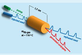
Scientists at the National Institute of Standards and Technology (NIST) are claiming to have achieved faster-than-light transfer of quantum data using something called four-wave mixing, which incidentally is a phenomenon that's considered a form of interference in fiber optic lines. The experiment involves sending a short 200-nanosecond seed pulse through heated rubidium vapor and at the same time sending in a second pump beam at a different frequency to amplify the seed pulse. Photons from both beams interact with the vapor in a way that generates a third beam. Apparently, the peaks of both the amplified seed pulse and the newly generated pulse can exit faster than a reference beam traveling at the speed of light in a vacuum. The speed differences they reported were 50 to 90 nanoseconds faster than light through a vacuum. They even proclaimed being able to tune the speed of the pulses by altering the input seed detuning and power.
Another fast data transfer technology in the works is quantum teleportation , which relies on the existence of entangled pairs: two particles that are in tune with each other to the point that if you measure one, the other ends up with the same quality that you found in the first one, no matter their distance from one another. This also requires a third particle that contains the actual bits of data you are trying to transfer. A laser is used to teleport one of the entangled particles elsewhere, in a manner of speaking. It isn't really transporting a photon, but rather changing a new photon into a copy of the original. The photon in the entangled pair can be compared to the third photon to find their similarities or differences, and that information can be relayed to the other location and used for comparison with the twin particle to glean the data. This sounds like something that would result in instant transfer, but that's not the case. Laser beams only travel at the speed of light. But this has potential applications for sending encrypted data via satellite, and for networking quantum computers, should we ever invent them. And it's further along than any attempts at superluminal data transfer. It works over miles at this point, and researchers are trying to increase the teleportation distance.
The answer to whether meaningful information can travel faster than light is currently no. We're only at the level of moving a few quantum particles at speeds that may possibly be over the speed of light, if the data pans out on subsequent experiments. To have a practically applicable form of data transfer, you have to be able to send organized bits of data that mean something, uncorrupted, to another machine that can interpret it. The fastest transmission in the world will mean nothing otherwise. But you can be sure that if the speed of light is broken, we'll be applying it to our Internet transmissions far sooner than to interstellar travel. Our ability to watch the highest quality television and surf the net at the fastest speeds will be paramount. And perhaps for those purposes, even getting ourselves to truly as-fast-as-light transmission would do wonders.
Frequently Answered Questions
Is it possible for information to travel faster than light, lots more information, author's note.
Physics is a truly fascinating subject, as it attempts to find the answer to how everything in the universe works. Without the study of physics, we probably wouldn't have a lot of modern conveniences, for instance those that require electricity, or depend upon the behavior of waves of any sort (like just about every form of long distance communication). You certainly wouldn't be reading this right now. Without an understanding of physical laws, lifting a piano would be more difficult, video games wouldn't be as much fun (or exist), and cartoon animators wouldn't know what laws to break to make us laugh. And we certainly wouldn't have ventured into space, an ability we'll need if we discover, via astrophysics or a keen observer, that a planet-destroying asteroid is headed our way. Also, kudos to mathematics for making the study of physics possible. I will continue to sit back and reap the benefits made possible by all the hard-working mathematicians, physicists and engineers of the world.
Related Articles
- Was there an error in the CERN team's timing of faster-than-light neutrinos?
- What if you traveled faster than the speed of light?
- 10 Best Ideas for Interplanetary Communication
- How the Large Hadron Collider Works
- What does CERN mean for the future of the universe?
- ABC Science. "Ask an Expert - Why is fibre optic technology 'faster' than copper?" (Nov. 24, 2012) http://www.abc.net.au/science/articles/2010/10/21/3044463.htm
- Alwayn, Vivek. "Optical Network Design and Implementation. Chapter: Fiber-Optic Technologies." Apr. 23, 2004. (Nov. 26, 2012) http://www.ciscopress.com/articles/article.asp?p=170740
- America's Library. "Alexander Graham Bell Invented the Photophone - June 3, 1880." (Dec. 2, 2012) http://www.americaslibrary.gov/jb/gilded/jb_gilded_bell_1.html
- Anderson, Nate. "Copper wire as fast as fiber?" Ars Technica. Oct. 10, 2006. (Nov. 24, 2012) http://arstechnica.com/gadgets/2006/10/7952/
- Anderson, Nate. "New life for twisted-pair? 500Mbps over copper wiring." Ars Technica. Mar. 16, 2009. (Nov. 25, 2012) http://arstechnica.com/tech-policy/2009/03/ericsson-500mbps-over-copper-wiring/
- Boyle, Rebecca. "Fed Up With Sluggish Neutrinos, Scientists Force Light To Move Faster Than Its Own Speed Limit." PopSci. May 3, 2012. (Nov. 26, 2012) http://www.popsci.com/science/article/2012-05/fed-sluggish-neutrinos-scientists-force-light-move-faster-its-own-speed-limit
- CBC News. "'Faster-than-light' data in doubt after new results." Mar. 19, 2012. (Nov. 15, 2012) http://www.cbc.ca/news/technology/story/2012/03/19/technology-faster-than-light-neutrinos-icarus.html
- CBC News. "'Faster-than-light' particles may have been even speedier." Feb. 23, 2012. (Nov. 15, 2012) http://www.cbc.ca/news/story/2012/02/23/technology-faster-than-light-neutrinos-opera.html
- Ceurstemont, Sandrine. "One-Minute Physics: Why light slows down in glass." New Scientist TV. Oct. 24, 2011. (Nov. 30, 2012) http://www.newscientist.com/blogs/nstv/2011/10/one-minute-physics-why-light-slows-down-in-glass.html
- Collins, Nick. "Speed of light 'broken' at CERN, scientists claim." The Telegraph. Sept. 22, 2011. (Nov. 30, 2012) http://www.telegraph.co.uk/science/science-news/8783011/Speed-of-light-broken-at-CERN-scientists-claim.html
- Condliffe, Jamie. "Did Scientists Really Just Break the Speed of Light?" Gizmodo. May 7, 2012. (Nov. 15, 2012) http://gizmodo.com/5908206/did-scientists-really-just-break-the-speed-of-light
- Das, Saswato R. "Was Einstein Wrong?" New York Times. Sept. 29, 2011. (Dec. 2, 2012) http://www.nytimes.com/2011/09/30/opinion/30iht-eddas30.html
- Diaz, Jesus. "Ridiculous: A Loose Cable Caused Those 'Faster-Than-Light' Particles." Gizmodo. Feb. 22, 2012. (Nov. 15, 2012) http://gizmodo.com/5887398/a-loose-cable-caused-the-faster+than+light-particles-test
- Dillow, Clay. "Physicists Say Speed-of-Light Breaking Neutrinos Would've Lost Their Energy Along the Way." PopSci. Oct. 3, 2011. (Nov. 30, 2012) http://www.popsci.com/science/article/2011-10/physicists-say-speed-light-breaking-neutrinos-wouldve-lost-their-energy-along-way
- Dodson, Brian. "Warp drive looks more promising than ever in recent NASA studies." Gizmag. Oct. 3, 2012. (Nov. 27, 2012) http://www.gizmag.com/warp-drive-bubble-nasa-interstellar/24392/
- FCC. "Measuring Broadband America - July 2012." July 2012. (Dec. 2, 2012) http://www.fcc.gov/measuring-broadband-america/2012/july
- Fettweis, Alfred. "Can signals truly be faster than light?" Signal Processing. August 2003, Volume 83, Issue 8, Pages 1583-1596. (Nov. 20, 2012)
- Finnie, Matthew. "How clouds cheat the speed of light." The Guardian. Sept. 6, 2012. (Nov. 24, 2012) http://www.guardian.co.uk/media-network/media-network-blog/2012/sep/06/cloud-computing-speed-light-network
- Glasser, Ryan T, Ulrich Vogl, and Paul D. Lett. "Stimulated generation of superluminal light pulses via four-wave mixing." Apr. 3, 2012. (Nov. 20, 2012) http://arxiv.org/pdf/1204.0810v1.pdf
- Hartley, Darleen. "Data Faster Than the Speed of Light." BSN. June 27, 2012. (Nov. 30, 2012) http://www.brightsideofnews.com/news/2012/6/27/data-faster-than-the-speed-of-light.aspx
- Higginbotham, Stacey. "Kotura: A startup betting on the speed of light in the data center." GigaOM. Nov. 23, 2012. (Nov. 25, 2012) http://gigaom.com/cloud/kotura-a-startup-betting-on-the-speed-of-light-in-the-data-center/
- Hsu, Jeremy. "Spaceship Could Fly Faster Than Light." Space.com. Aug. 13, 2008. (Dec. 1, 2012) http://www.space.com/5725-spaceship-fly-faster-light.html
- Iannone, P. "Optical Communications." IEEE Photonics Society. (Nov. 24, 2012) http://www.photonicssociety.org/content/optical-communications
- Johnston, James H. "Internet With the Speed of Light." Legal Times. Volume XXV, Issue 45, Nov. 18, 2002. (Nov. 30, 2012) http://www.ieeeusa.org/communications/Massmedia/files/Internet%20With%20the%20Speed....pdf
- Kawalec, Tomasz. "Should we bother with the speed of light in everyday life? A closer look at GSM technology." Physics Education. Volume 47, Issue 5, Pages 579-583. September 2012. (Nov. 15, 2012)
- Knapp, Alex. "Chinese Researchers Quantum Teleport Photons Over 60 Miles." Forbes. May 11, 2012. (Nov.25, 2012) http://www.forbes.com/sites/alexknapp/2012/05/11/chinese-researchers-quantum-teleport-photons-over-60-miles/
- Lentine, A. "Optical Interconnects & Processing Systems." IEEE Photonics Society. (Nov. 24, 2012) http://www.photonicssociety.org/content/optical-interconnects-processing-systems
- Mann, Adam. "The Race to Bring Quantum Teleportation to Your World." Wired. Oct. 3, 2012. (Dec. 2, 2012) http://www.wired.com/wiredscience/2012/10/quantum-satellite-teleportation/all/
- Mims, Christopher. "Achieving Fiber Optic Speeds over Copper Lines." MIT Technology Review. Apr. 22, 2012. (Nov. 25, 2012) http://www.technologyreview.com/news/418646/achieving-fiber-optic-speeds-over-copper-lines/
- Moskowitz, Clara. "Einstein's math may also describe faster-than-light velocities." Christian Science Monitor. Oct. 10, 2012. (Dec. 1, 2012) http://www.csmonitor.com/Science/2012/1010/Einstein-s-math-may-also-describe-faster-than-light-velocities
- Page, Lewis. "US gov boffins achieve speeds FASTER THAN LIGHT - 'Loophole' found in Special Theory of Relativity." The Register. May 7, 2012. (November 15, 2012) http://www.theregister.co.uk/2012/05/07/faster_than_light_quantum/
- Pennsylvania State University. "Researchers push transmission rate of copper cables." Nov. 14, 2007. (Nov. 24, 2012) http://live.psu.edu/story/27265
- Plumb, Marisa. "Copper at the Speed of Fiber?" IEEE Spectrum. October 2011. (Nov. 25, 2012) http://spectrum.ieee.org/telecom/internet/copper-at-the-speed-of-fiber
- Quigley, Brian. "Speed of Light in Fiber - The First Building Block of a Low-Latency Trading Infrastructure." Technically Speaking. Apr. 7, 2011. (Nov. 30, 2012) http://blog.advaoptical.com/speed-light-fiber-first-building-block-low-latency-trading-infrastructure/
- Reich, Eugenie Samuel. "Neutrino experiment replicates faster-than-light finding." Nature. Nov. 18, 2011. (Nov. 15, 2012) http://www.nature.com/news/neutrino-experiment-replicates-faster-than-light-finding-1.9393
- Schneider, David. "Financial Trading at the Speed of Light." IEEE Spectrum. Oct. 2011. (Nov. 25, 2012) http://spectrum.ieee.org/computing/it/financial-trading-at-the-speed-of-light
- Wrenn, Eddie. "Can we finally break the speed of light? Nasa breakthrough suggested Star Trek's 'warp drives' may not only be possible - but practical." Daily Mail. Sept. 18, 2012. (Dec. 1, 2012) http://www.dailymail.co.uk/sciencetech/article-2204913/Nasa-breakthrough-suggests-Star-Treks-warp-drives-possible--practical.html
- Wright, Robert. "Richard Feynman on the Weirdness of Physical Reality." Video of lecture at Cornell University: The Character of Physical Law: Probability and Uncertainty - The Quantum Mechanical View of Nature - November 18, 1964. The Atlantic. July 11, 2012. (Nov. 30, 2012) http://www.theatlantic.com/technology/archive/2012/07/richard-feynman-on-the-weirdness-of-physical-reality/259718/
Please copy/paste the following text to properly cite this HowStuffWorks.com article:

The New York Times
Technology | how the internet travels across oceans, how the internet travels across oceans.
MARCH 10, 2019
‘People think that data is in the cloud, but it’s not. It’s in the ocean.’
Internet cables in service by 2021
- Undersea cables owned by Amazon , Facebook , Google or Microsoft
- Other undersea cables
By ADAM SATARIANO Graphics by KARL RUSSELL, TROY GRIGGS and BLACKI MIGLIOZZI Photographs by CHANG W. LEE
The internet consists of tiny bits of code that move around the world, traveling along wires as thin as a strand of hair strung across the ocean floor. The data zips from New York to Sydney, from Hong Kong to London, in the time it takes you to read this word.
Nearly 750,000 miles of cable already connect the continents to support our insatiable demand for communication and entertainment. Companies have typically pooled their resources to collaborate on undersea cable projects, like a freeway for them all to share.
But now Google is going its own way, in a first-of-its-kind project connecting the United States to Chile, home to the company’s largest data center in Latin America.
“People think that data is in the cloud, but it’s not,” said Jayne Stowell, who oversees construction of Google’s undersea cable projects. “It’s in the ocean.”
Getting it there is an exacting and time-intensive process. A 456-foot ship named Durable will eventually deliver the cable to sea. But first, the cable is assembled inside a sprawling factory a few hundred yards away, in Newington, N.H. The factory, owned by the company SubCom, is filled with specialized machinery used to maintain tension in the wire and encase it in protective skin.
The cables begin as a cluster of strands of tiny threads of glass fibers. Lasers propel data down the threads at nearly the speed of light, using fiber-optic technology. After reaching land and connecting with an existing network, the data needed to read an email or open a web page makes its way onto a person’s device.
While most of us now largely experience the internet through Wi-Fi and phone data plans, those systems eventually link up with physical cables that swiftly carry the information across continents or across oceans.
In the manufacturing process, the cables move through high-speed mills the size of jet engines, wrapping the wire in a copper casing that carries electricity across the line to keep the data moving. Depending on where the cable will be located, plastic, steel and tar are added later to help it withstand unpredictable ocean environments. When finished, the cables will end up the size of a thick garden hose.
A year of planning goes into charting a cable route that avoids underwater hazards, but the cables still have to withstand heavy currents, rock slides, earthquakes and interference from fishing trawlers. Each cable is expected to last up to 25 years.
A conveyor that staff members call “the Cable Highway” moves the cable directly into Durable, docked in the Piscataqua River. The ship will carry over 4,000 miles of cable weighing about 3,500 metric tons when fully loaded.
Inside the ship, workers spool the cable into cavernous tanks. One person walks the cable swiftly in a circle, as if laying out a massive garden hose, while others lie down to hold it in place to ensure it doesn’t snag or knot. Even with teams working around the clock, it takes about four weeks before the ship is loaded up with enough cable to hit the open sea.
The first trans-Atlantic cable was completed in 1858 to connect the United States and Britain. Queen Victoria commemorated the occasion with a message to President James Buchanan that took 16 hours to transmit .
While new wireless and satellite technologies have been invented in the decades since, cables remain the fastest, most efficient and least expensive way to send information across the ocean. And it is still far from cheap: Google would not disclose the cost of its project to Chile, but experts say subsea projects cost up to $350 million, depending on the length of the cable.
In the modern era, telecommunications companies laid most of the cable, but over the past decade American tech giants started taking more control. Google has backed at least 14 cables globally. Amazon, Facebook and Microsoft have invested in others, connecting data centers in North America, South America, Asia, Europe and Africa, according to TeleGeography, a research firm.
Countries view the undersea cables as critical infrastructure and the projects have been flash points in geopolitical disputes. Last year, Australia stepped in to block the Chinese technology giant Huawei from building a cable connecting Australia to the Solomon Islands, for fear it would give the Chinese government an entry point into its networks.
Content providers like Microsoft , Google , Facebook and Amazon now own or lease more than half of the undersea bandwidth

Share of used international
undersea cable bandwidth

Yann Durieux, a ship captain, said one of his most important responsibilities was keeping morale up among his crew during the weeks at sea. Building the infrastructure of our digital world is a labor-intensive job.
With 53 bedrooms and 60 bathrooms, the Durable can hold up to 80 crew members. The team splits into two 12-hour shifts. Signs warn to be quiet in the hallways because somebody is always sleeping.
The ship will carry enough supplies to last at least 60 days: roughly 200 loaves of bread, 100 gallons of milk, 500 cartons of a dozen eggs, 800 pounds of beef, 1,200 pounds of chicken and 1,800 pounds of rice. There are also 300 rolls of paper towels, 500 rolls of toilet paper, 700 bars of soap and almost 600 pounds of laundry detergent. No alcohol is allowed on board.
“I still get seasick,” said Walt Oswald, a technician who has been laying cables on ships for 20 years. He sticks a small patch behind his ear to hold back the nausea. “It’s not for everybody.”
Poor weather is inevitable. Swells reach up to 20 feet, occasionally requiring the ship captain to order the subsea cable to be cut so the ship can seek safer waters. When conditions improve, the ship returns, retrieving the cut cable that has been left attached to a floating buoy, then splicing it back together before continuing.
Work on board is slow and plodding. The ship, at sea for months at a time, moves about six miles per hour, as the cables are pulled from the giant basins out through openings at the back of the ship. Closer to shore, where there’s more risk of damage, an underwater plow is used to bury the cable in the sea floor.
The Durable crew doesn’t expect the work to slow down anytime soon.
After the Latin America project, Google plans to build a new cable running from Virginia to France, set to be done by 2020. The company has 13 data centers open around the world, with eight more under construction — all needed to power the trillions of Google searches made each year and the more than 400 hours of video uploaded to YouTube each minute.
“It really is management of a very complex multidimensional chess board,” said Ms. Stowell of Google, who wears an undersea cable as a necklace.
Demand for undersea cables will only grow as more businesses rely on cloud computing services. And technology expected around the corner, like more powerful artificial intelligence and driverless cars, will all require fast data speeds as well. Areas that didn’t have internet are now getting access, with the United Nations reporting that for the first time more than half the global population is now online.
“This is a huge part of the infrastructure that’s making that happen,” said Debbie Brask, the vice president at SubCom, who is managing the Google project. “All of that data is going in the undersea cables.”
Note: Cables shown in the map are ones that are currently in use, planned or being constructed. They do not show cables that were decommissioned. The content providers comprise cables publicly announced that Facebook, Google, Microsoft or Amazon partly own, solely own or are a major capacity buyer of a cable owned by another company. | Source: TeleGeography
More on NYTimes.com
Advertisement
Trending People
trending technology, trending entities.
- Systems & Design
- Low Power - High Performance
- Manufacturing, Packaging & Materials
- Test, Measurement & Analytics
- Auto, Security & Pervasive Computing
- Startup Corner
- Industry Research
- Special Reports
- Business & Startups
- Knowledge Center
- Architectures
- Automotive/ Aerospace
- Communication/Data Movement
- Design & Verification
- Lithography
- Manufacturing
- Optoelectronics / Photonics
- Power & Performance
- Test, Measurement & Analytics
- Transistors
- Z-End Applications
- Newsletters
- Low Power-High Performance
- Technical Papers
How Much Data Can Be Pushed Through Copper Wires?
Pushing toward the Shannon signaling capacity using less energy consumption.

As the amount of digital data grows, so do requirements on the speed of the transmission at all levels of the transmission chain—between dies in a shared package, between packaged chips inside a device, and between devices. The communication channels encountered at every stage of this communication are different in nature. Those between dies in a shared package, or between packaged chips in a shared device, are mostly electrical wires. Those between devices can be electrical (as is the case when you connect a laptop to a monitor using a cable), or optical, as is the case when top of the rack switches are connected in a datacenter over longer distances, or even wireless. Each of these channels has its own properties, and communication across them ideally would be orchestrated in such a way as to utilize that channel in the best possible way.
But what is this “best possible way?” In other words, how many bits per second can one transmit on these channels, at least theoretically? An answer to this question will shed some light on how far we are away from these bounds, and how much “air” we still have to breathe.
By far the best answer to this question has been provided by Shannon’s definition of the “channel capacity.” In his seminal 1948 paper he associates with every communication channel a number, called its capacity, and shows that communication on this channel at any rate below this capacity is possible with a residual error that can be made arbitrarily small. At the same time, communication at any rate above the capacity only can be done at the cost of a fixed communication error. Loosely phrased, reliable communication at a given rate is possible if, and only if, that rate is below capacity. Unfortunately, though, Shannon doesn’t tell us how to design efficient communication systems that operate at rates close to the capacity.
Given this fundamental relationship, it seems logical to measure the throughput of any given communication system against the capacity of the underlying channel. This is where we have a huge disconnect between electrical chip-to-chip links, and practically all other important communication channels such as wireless, optical, satellite, DSL, etc.
In all these other communication channels researchers have found ways to come close to the Shannon capacity of the underlying channel. As an example, consider the so-called Additive White Gaussian Noise (AWGN) channel in which transmitted signals are subjected independently to Gaussian noise of mean 0 and variance s2. This is a prototypical channel for wireless communication as results for many other channels can be derived from those for the AWGN channel. If transmitted bits use, on average, a power of P, then the capacity of this communication channel, i.e., the maximum rate at which bits can be transmitted reliably, is B * log2( 1 + P/s2) where B is the bandwidth in Hz.
For chip-to-chip communication, similar formulas can be derived as a function of the underlying channel loss parameters. We are not going to get into the details of these computations, but instead offer an illuminating comparison to wireless channels.

As can be seen, in the wireless world communication rates are quite close to the Shannon capacity of the underlying channel, whereas in chip-to-chip communication over electrical wires the transmission rates are extremely far off. Let’s look at numbers, for example for a channel typically encountered in ultra-short-reach (USR) communication between dies in a shared package. If the SNR (ratio between the average signal power on each wire and the variance of the thermal noise) is 70 dB, then the capacity is about 165 Gbps. How does this compare to today’s communication systems? This SNR corresponds to a peak-to-peak single-ended voltage of 300 mV and a thermal noise standard deviation of 1 mV w hen using Kandou’s CNRZ-5 Chord Signaling. Kandou’s Glasswing IP achieves approximately 21 Gbps per wire in this generation, and 42 Gbps in the next, while the capacity is 165 Gbps—still away from the capacity, but better than other signaling schemes. For example, for the same power on the wires, differential signaling would have an SNR of 60 dB and a capacity of 124 Gbps, and PAM-4 an SNR of 63 dB and a capacity of 138 Gbps. We are not aware of commercial USR IP’s that use NRZ or PAM-4 at such high speeds.
So why is it that we are still so far off the capacity in chip-to-chip communication? There are several reasons for this. One is that chip-to-chip communication is extremely power-constrained. In fact, the power of signals on the wires is only a small fraction of the total power of the communication system, something that is in stark contrast to systems like wireless. Another reason is the use of ADC’s and advanced DSP algorithms in other communication systems. This is justified because the power used by the ADC and the DSP is miniscule compared to the total power of the system. In chip-to-chip communication this is not the case. Yet another reason is latency. Because of ultra-high speeds in chip-to-chip communication, the tolerated latency is quite small (maybe in the range of a few 100’s of UI). It is difficult to use techniques like strong FEC in such a latency-constrained system.
All of these issues point to the need for radically new techniques that require very little power and yet are capable of approaching the Shannon capacity of the underlying channel. Kandou’s Chord Signaling is one such modulation scheme. In the years to come, Kandou will introduce new methods on top of Chord signaling to increase the throughput with the goal of approaching the Shannon capacity at low energy consumption. The next generation of modulation techniques is already at R&D stage at Kandou and will be introduced to the market in the near future.
Jeff McGuire
Leave a reply cancel reply.
Name * (Note: This name will be displayed publicly)
Email * (This will not be displayed publicly)
- Merging Power and Arithmetic Optimization Via Datapath Rewriting (Intel, Imperial College London) April 19, 2024 by Technical Paper Link
- RF General-Purpose Photonic Processor April 17, 2024 by Technical Paper Link
- Memristor Crossbar Architecture for Encryption, Decryption and More April 16, 2024 by Technical Paper Link
- Single-Molecule Transistor Using Quantum Interference April 16, 2024 by Technical Paper Link
- Feasibility and Potential of Quantum Computing For a Typical EDA Optimization Problem April 16, 2024 by Technical Paper Link
Knowledge Centers Entities, people and technologies explored
Related articles, an overview of federal government semiconductors and microelectronics standards activities (nist), benchmarking electron holography and pixelated stem on various semiconductor structures, high-na euvl: automated defect inspection based on semi-superyolo-nas, newsletter signup, popular tags, recent comments.
- Anne Meixner on Too Much Fab And Test Data, Low Utilization
- Mark Hahn on CXL: The Future Of Memory Interconnect?
- Dr. Richard Roy on Future-Proofing Automotive V2X
- Frank-Peter Ludwig on Enabling Advanced Devices With Atomic Layer Processes
- Piyush Kumar Mishra on Using AI/ML To Minimize IR Drop
- Rakesh on Timing Library LVF Validation For Production Design Flows
- Mike Cawthorn on What Will That Chip Cost?
- Liz Allan on Early STEM Education Key To Growing Future Chip Workforce
- Rob Pearson - RIT on Early STEM Education Key To Growing Future Chip Workforce
- Maury Wood on Examining The Impact Of Chip Power Reduction On Data Center Economics
- Erik Jan Marinissen on Chiplet IP Standards Are Just The Beginning
- Peter Bennet on Design Tool Think Tank Required
- Dr. Dev Gupta on Chiplet IP Standards Are Just The Beginning
- Jesse on Hunting For Open Defects In Advanced Packages
- Matt on Chip Ecosystem Apprenticeships Help Close The Talent Gap
- Leonard Schaper IEEE-LF on 2.5D Integration: Big Chip Or Small PCB?
- Apex on Nanoimprint Finally Finds Its Footing
- AKC on Gearing Up For Hybrid Bonding
- Allen Rasafar on Backside Power Delivery Gears Up For 2nm Devices
- Nathaniel on Intel, And Others, Inside
- Chris G on Intel, And Others, Inside
- Richard Collins on Too Much Fab And Test Data, Low Utilization
- Jerry Magera on Why Chiplets Are So Critical In Automotive
- Jenn Mullen on Shattered Silos: 2024’s Top Technology Trends
- Valerio Del Vecchio on Security Becoming Core Part Of Chip Design — Finally
- Lucas on Hybrid Bonding Basics: What Is Hybrid Bonding?
- Robin Grindley on Expand Your Semiconductor’s Market With Programmable Data Planes
- V.P.Sampath on RISC-V Micro-Architectural Verification
- Thermal Guy on Is UCIe Really Universal?
- Colt Wright on Shattered Silos: 2024’s Top Technology Trends
- Nicolas Dujarrier on The Future Of Memory
- Tony on Challenges Of Logic BiST In Automotive ICs
- Raymond Meixner's child on Visa Shakeup On Tap To Help Solve Worker Shortage
- Michael Alan Bruzzone on How Is The Chip Industry Really Doing?
- Art Scott on How Is The Chip Industry Really Doing?
- Liz Allan on Rethinking Engineering Education In The U.S.
- Telkom University on Rethinking Engineering Education In The U.S.
- Ramesh Babu Varadharajan on SRAM’s Role In Emerging Memories
- jake_leone on Visa Shakeup On Tap To Help Solve Worker Shortage
- d0x on How Secure Are FPGAs?
- Mike Bradley on RISC-V Micro-Architectural Verification
- Charles E. Bauer ,Ph.D. on Visa Shakeup On Tap To Help Solve Worker Shortage
- AMAN SINGH on Power Aware Intent And Structural Verification Of Low-Power Designs
- Ed Trevis on Visa Shakeup On Tap To Help Solve Worker Shortage
- AMAN SINGH on Get To Know The Gate-Level Power Aware Simulation
- Pitchumani Guruswamy on RISC-V Micro-Architectural Verification
- Manil Vasantha on AI Accelerator Architectures Poised For Big Changes
- Ramachandra on Packaging Demands For RF And Microwave Devices
- garry on New Insights Into IC Process Defectivity
- Brian Bailey on The Good Old Days Of EDA
- Ann Mutschler on AI Accelerator Architectures Poised For Big Changes
- John Derrick on AI Accelerator Architectures Poised For Big Changes
- allan cox on AI Accelerator Architectures Poised For Big Changes
- Madhusudhanan RAVISHANKAR on Curbing Automotive Cybersecurity Attacks
- Eric Cigan on The Good Old Days Of EDA
- Peter Flake on The Good Old Days Of EDA
- Mike Cummings on MEMS: New Materials, Markets And Packaging
- Bill Martin on The Good Old Days Of EDA
- Gretchen Patti on 3D-ICs May Be The Least-Cost Option
- Carlos on An Entangled Heterarchy
- Ann Mutschler on Flipping Processor Design On Its Head
- Gil Russell on Flipping Processor Design On Its Head
- Ed Sperling on China Unveils Memory Plans
- David on The Limits Of AI-Generated Models
- Bill on The Limits Of AI-Generated Models
- Dr. Dev Gupta on Gearing Up For Hybrid Bonding
- Faizan on China Unveils Memory Plans
- Jan Hoppe on Streamlining Failure Analysis Of Chips
- Riko R on Why Curvy Design Now? Manufacturing Is Possible And Scaling Needs It
- Derrick Meyer on Higher Automotive MCU Performance With Interface IP
- Kevin Cameron on Why Silent Data Errors Are So Hard To Find
- Rale on How Secure Are RISC-V Chips?
- Ed Sperling on Patterns And Issues In AI Chip Design
- Chip Greely on Building Better Bridges In Advanced Packaging
- Art Scott on Setting Standards For The Chip Industry
- Muhammet on Higher Creepage And Clearance Make For More Reliable Systems
- Andy Deng on Quantum Plus AI Widens Cyberattack Threat Concerns
- Dr. Rahul Razdan on The Threat Of Supply Chain Insecurity
- Roger on Patterns And Issues In AI Chip Design
- David Leary on Improving Reliability In Chips
- Ann Mutschler on The Threat Of Supply Chain Insecurity
- Cliff Greenberg on Setting Standards For The Chip Industry
- Kevin Parmenter on The Threat Of Supply Chain Insecurity
- Esther soria on Automotive Complexity, Supply Chain Strength Demands Tech Collaboration
- Kumar Venkatramani on Predicting The Future For Semiconductors
- Spike on Is UCIe Really Universal?
- David Sempek on Power Semis Usher In The Silicon Carbide Era
- Dp on Specialization Vs. Generalization In Processors
- Eric on Addressing The ABF Substrate Shortage With In-Line Monitoring
- Karl Stevens Logic Designer on Software-Hardware Co-Design Becomes Real
- Jim Handy on MRAM Getting More Attention At Smallest Nodes
- Nicolas Dujarrier on MRAM Getting More Attention At Smallest Nodes
- Lou Covey on Are In-Person Conferences Sustainable?
- Cas Wonsowicz on AI Transformer Models Enable Machine Vision Object Detection
- Nancy Zavada on Are In-Person Conferences Sustainable?
- Fred Chen on High-NA Lithography Starting To Take Shape
- Dave Taht on Wi-Fi 7 Moves Forward, Adding Yet Another Protocol
- Robert Boissy on Rethinking Engineering Education In The U.S.
- Allen Rasafar on High-NA Lithography Starting To Take Shape
- Mathias Tomandl on Multi-Beam Writers Are Driving EUV Mask Development
- K on High-NA Lithography Starting To Take Shape
- Adibhatla krishna Rao on How Do Robots Navigate?
- Doug L. on Getting Rid Of Heat In Chips
- Ken Rygler on DAC/Semicon West Wednesday
- Mark Camenzind on Why IC Industry Is Great Place To Work
- Peter Bennet on The True Cost Of Software Changes
- ALLEN RASAFAR on Balancing AI And Engineering Expertise In The Fab
- Ron Lavallee on The True Cost Of Software Changes
- Alex Peterson on Welcome To EDA 4.0 And The AI-Driven Revolution
- Allen Rasafar on Managing Yield With EUV Lithography And Stochastics
- Art Scott on Rethinking Engineering Education In The U.S.
- Paul Clifton on Week In Review: Semiconductor Manufacturing, Test
- Mark L Schattenburg on A Highly Wasteful Industry
- Gordon Harling on Rethinking Engineering Education In The U.S.
- Santosh Kurinec on Rethinking Engineering Education In The U.S.
- Brian Bailey on Rethinking Engineering Education In The U.S.
- CdrFrancis Leo on Will There Be Enough Silicon Wafers?
- Advertising on SemiEng
- Newsletter SignUp
- Low Power-High Perf
- Knowledge Centers
Connect With Us
- Twitter @semiEngineering
Privacy Overview
How Does Data Travel on the Internet?
When you open a browser and go to a webpage, data is traveling through the internet, to a server to get the content. It then travels back to serve you that content on your computer. But how does data travel on the internet, really? I mean, how does it go to a server and back that fast?
In networking, data is called packets. These packets are what matters and they have everything needed in them, like the destination address and the request. To understand it better, let’s dive deeper into how data actually travels over the internet in this article.
What is a Data Packet?
A data packet, or network packet to be correct, is a collection name of several components. These components are needed in order for you to be able to browse the web, for example. In order for you to go to a website, you will need to send packets to the websites web server and that server will have to send packets back to you. For this to work, a packet needs to hold several components:
- IP Addresses
First, the packet needs two addresses, the source address, and the destination address. How would it else know where to go and where it came from?
A packet has something called “time to live”. This is the number of hops the packet can do until it dies. Each time the packet goes through a network node (i.e a router or a switch, like a crossing) the number is decreased. This is to avoid packets with errors hopping around the web for eternity.
Depending on what the packet carries, one packet may not be enough. Each packet consists of a length so that the receiver knows if the packet came alone or if more is to come.
This is the actual data, the content of the packet.
A packet can also include other components, but these are the main ones that are always there. Network packets are how information (data) is being carried over the internet. But how does the packet travel?
As you know, this data packet will not just magically appear somewhere else, it needs to find the destination and then get there. For the package to know where to go, something called routing will be used. This is essentially just your local post office carrying out post. The mailman looks at the zip code, then the address, then the house number and then the name, and data packets do the same thing.

Data takes the highway.
How the data is being transmitted is through cables. It might start off as a package on your mobile phone and will wirelessly be transferred to your router. WiFi signals are working like waves, much like radio signals. I highly suggest taking a look at this article from vice.com , where they have imagined how WiFi would like if we could see it.
Once the router has received the signals from your phone, the packet will continue through cables, from your router and out to the world wide web. Your house is most likely connected to the grid in your city. The packet has its address written on it and will go where the signs are pointing.
The signs, in this case, is called DNS, or Domain Name Servers. These exist to tell other services, servers, clients and data packets where to go. Often, a DNS will point to another DNS that is closer to the destination. However, if the DNS knows where the destination is, it will point directly there instead.
As you can tell, it is very much like a parcel, motorways, and crossings. It’s very easy to see the similarities and that is because it works in the same way. Why change something if it works?
How Fast Does Data Travel on the Internet?
Fast. No, really, it’s fast.
In a fiberoptic cable, which is what companies are digging down, the speed for a data packet is about 200 000 km/s (124 300 miles/second. To give you some sort of reference on how fast that is, the circumference of the Earth is about 40 000 km. This means that the packet can go 5 times around the globe in a fiberoptic cable.

Takes some more time for us humans to travel around the world.
But we are not done. Because packets can move even faster in the air. Without interference, they can reach speeds of up to 99.7% the speed of light, or 299 100 km/s. That is two hundred thousand one hundred kilometers per second or 185 723 miles per second. That is insane. In the air, the packet can go 7 times around the Earth, at the same time it takes you to blink your eye.
Now, to be real, it’s not possible to count as that all the time as there are obstacles in the way. Things like routers, switches, and other nodes do not support this kind of speeds (unsurprisingly) so they are the bottlenecks. Think about that the next time you are thinking that your internet is slow.
Who Owns the Internet and is Responsible?
This is the good thing with the internet, and something that has made the internet become so big as it actually is (what I think anyway). There is no one that owns the internet. There is no government, no company, no organization. There is no CEO on the top that can go bad and shut it down any minute.
Since the internet is a hard thing to grasp, let’s focus on what it relies on instead: hardware. Here, many organization and companies provide their hardware for the internet to work efficiently. Your ISP, for example, has servers, switches, and routers that make their part of the internet working as it should. They are then connected to another company or organization that take over.
So, if all companies in the whole world press the off-button at the same time, the internet would go down. On the other hand, that would never happen as these companies make tons of money on the internet, and money talks 🙂
Because of the above, there is no one that is responsible for the overall internet. There are organizations that will standardize technology and infrastructure, so that is easier for these companies to talk to each others. You may have heard of some of these organizations, like ICANN (Internet Corporation for Assigned Names and Numbers) or IETF (Internet Engineering Task Force) . However, these organizations are not responsible for the internet.

Leave a Reply Cancel reply
Your email address will not be published. Required fields are marked *
16 comments on “How Does Data Travel on the Internet?”
Many people now use internet and wifi, but not all of them are really concern about their secure and safe internet connection.
I am not an internet technology expert, but I love people share about technology and teach people about the digital security. Thanks you for this amazing post, this is lovely.
I agree. I glad you enjoy what I consider a passion of mine. Always happy to help.
Good read. Thanks.
Crazy read. Thanks.
You're welcome! 🙂
Thanks for this page. Great to read.
Thank you Beau! Glad you enjoyed it.
Hi I am saving this post for my personal database of references. Its great.
Thanks for reading Chris! Glad it’s proven useful!
So . . . you are saying that data can travel faster than light then? Fiberoptic in air without interference = 186 400 miles per second Speed of light through air = 186 282 miles per second
Thanks for reading.
So that's not true, and in this case the numbers used are rounded approximations. The speed on light in a fiber optic cable with air at optimal conditions can travel at 99.7% the speed of light.
The approximate speed of light is 300,000 kilometers per second, or 186,282 miles per second. So with that, data in a fiber optic cable could hypothetically travel at 299,100 kilometers per second or 185,723.154 miles per second.
For reference, refer to this Ars Technica article. https://arstechnica.com/information-technology/2013/03/fiber-cables-made-of-air-move-data-at-99-7-percent-the-speed-of-light/
I have made a correction in the article to reflect that. Thanks for catching it!
can you do a summary?
So Data travels on the internet using a construct called packets, that contain information such as IP Address, Hops, Length and Payload. This data usually travels through cables, whether it be copper cables or fiber optic cables, or ever increasingly, wireless transmission (5G, satellite, etc).
To get to websites or other web services, we use a system called DNS (Domain Name System) because devices don’t understand Domain Names (website names), they understand IP Addresses. DNS converts a website name to an IP Address.
Data travels roughly at the speed of light, depending on the medium its traveling through (for wireless technology, its roughly the speed of sound). Data traveling through copper its a bit less than the speed of light, but with fiber optic cables it can be up to 99.7% the speed of light, given recent advancements.
The internet is managed through many Non Government Organizations (NGOs) like ICANN (Internet Corporation For Assigned Names and Numbers) and IETF (Internet Engineering Task Force).
Hope this is what you’re looking for!
Thanks orest
You're welcome, thanks for reading Able!
Recent Posts
Best wifi extender for ring camera, how long do modems last, xfinity modem router blinking orange, xfinity modem router blinking green, xfinity modem router blinking blue, xfinity modem router blinking white.
Privacy Policy | Disclaimer
- The Open University
- Guest user / Sign out
- Study with The Open University
My OpenLearn Profile
Personalise your OpenLearn profile, save your favourite content and get recognition for your learning
About this free course
Become an ou student, download this course, share this free course.

Start this free course now. Just create an account and sign in. Enrol and complete the course for a free statement of participation or digital badge if available.
5 Signal transmission
5.1 transmission of electrical signals on wires.
In the discussions of newsgathering in the Taylor and Higgins papers, you saw the significance of the development of systems that allowed long-distance transmission of electronic signals. Initially transmission used metallic wires (remember Taylor's reference to the importance of the 'lines infrastructure' and his mention of the 'wire picture') and later wireless transmission (terrestrial and satellite microwave) became important. In this section I shall look at some aspects of the transmission of digital signals, starting with a close look at the transmission of electrical signals on wires.
Using a wire to transmit a signal is simple in principle: you operate a switch at one place and observe the effect somewhere else. In Figure 17 I have shown this as a light coming on at a remote location. Notice in this diagram the standard symbol for a battery consisting of two parallel lines, one shorter than the other, and the symbol for a light bulb which is a circle with a cross in it. The standard symbol for a switch that can be 'open' or 'closed' consists of two dots and a line which either connects the dots (when the switch is closed as in Figure 17b ) or misses one of the dots (when the switch is open, as in Figure 17a ). To switch the light on you close the switch so that there is an electric circuit from the battery to the light bulb and back again. To switch the light off you open the switch to 'break' the circuit.

When you switch a light on, the light appears to come on immediately. There does not appear to be any delay between operating the switch and the effect at the light (although, depending on the type of light there might be a delay before it comes on fully – this is especially noticeable with fluorescent light tubes). In reality there is a delay – it is just very short indeed.
To get a better insight into what is happening, imagine measuring the voltage between the wires. This can be done with something called a voltmeter ( Figure 18 ). A voltmeter has two wires and a display. When you touch the ends of the wires to the terminals of a power source like a battery, the display on the meter tells you what the voltage is between the terminals.

Imagine using the voltmeter to measure the voltage between the two wires at some point between the switch and the light, as in Figure 19 . When the switch is open (off) the reading on the meter will be zero. When the switch is closed (on), the reading will (ideally) be equal to the voltage of the battery – which I shall assume is 1.2 volts. Now imagine having the voltmeter touching the wires while the switch is changed from open to closed. In this case you will see the voltage change from 0 to 1.2 V.

Now, if the voltmeter is touching the wires right next to the switch, you would see the voltage rise from 0 to 1.2 V at the same instant as the switch is closed. If, on the other hand, the voltmeter is touching the wires further away from the switch there will be a delay between the switch closing and the voltage rising. We can display this by plotting graphs as shown in Figure 20 .

These graphs show how the reading on the voltmeter changes with time. Along the horizontal axis from left to right corresponds to time passing, and up the vertical axis corresponds to increasing voltage, as measured by the voltmeter.
By convention, the axis that goes across the page is the 'horizontal' axis, and the axis that goes up and down the page is the 'vertical' axis. Sometimes they are called the x and y axes, for horizontal and vertical respectively.
The time axis is labelled in units of microseconds, where one microsecond is one-millionth of a second. Notice also that the time axis is relative to some time origin which is labelled 0. The actual time corresponding to 0 as shown on the axis might have been, say, Thursday 20 May 2004, 2.17 pm and 35.031233 seconds, but labelling the axis with that level of detail would be confusing and irrelevant.
Figure 20 (a) shows what the voltmeter would do when connected to the wires next to the switch, while Figure 20 (b) shows what it would do when connected to the wires 200 m along towards the light bulb. The switch was closed at time 1, on this scale, so the voltage measured next to the switch rises at time 1.
There is a delay before the voltage rises at the voltmeter when it is 200 m along the wire.
Activity 25
How much of a delay?
The voltage rises when the time is equal to 2 microseconds. The switch was closed at a time equal to 1 microsecond, so there is one-microsecond delay between the switch being closed and the voltage changing 200 m along the wire.
We can think of the change in voltage moving along the wires. This idea of the change in voltage moving along the wire becomes clear if we think about turning the light on and then off again afterwards. This is illustrated in Figure 21 .

Here, the switch is closed at time 1 microsecond and opened again at time 3 microseconds. We now have a voltage pulse . Looking at the voltage across the wires 200 m from the switch, both the rise and fall in voltage happen 1 microsecond later, and the voltage pulse has taken 1 microsecond to travel the 200 m along the wires.
I now say 'look at the voltage' rather than 'the value on the voltmeter'. I only introduced the idea of the (idealised) voltmeter to set up the concept of the voltage having a value at some place on the wires.
Activity 26
How fast is the pulse travelling, measured in metres per second?
The pulse travels 200 metres in 1 microsecond. 1 microsecond is one-millionth of a second, so in 1 second it would travel 200×1 million metres=200 million metres or 2×10 8 metres. The speed is therefore 2×10 8 m/s.
This is two-thirds of the speed of light, which is typical of the speed that electric signals travel along wires.
Activity 27
Assuming that the pulse continues to travel at the same speed, draw a graph of voltage against time for measurements taken 600 metres from the switch.
The pulse travels 200 m in 1 microsecond, so it takes 3 microseconds to travel 600 m. The pulse will be as in Figure 22 .

Figures 20 and 21 (and my answer to Activity 27) are simplifications because they have not shown attenuation or distortion. Figure 23 shows the sort of effects that attenuation and distortion might have on a pulse.

Attenuation reduces the height of the pulse, so that it does not reach 1.2 volts any more. Some of the voltage has been 'lost' as it travels the 200 metres because some energy from the electricity is absorbed by (very slightly) heating the wires and some energy is radiated into the air as the wires act as a (very inefficient) aerial.
Distortion alters the pulse, rounding the corners and generally changing the shape. Qualitatively, the smoothing of the corners is because the wires do not allow the voltage to change instantaneously – there is a sort of electrical drag as the pulse travels along the wires. More random distortion effects are caused by what is referred to as noise . By analogy with the common meaning of noise as unwanted, meaningless sounds, noise in the context of electrical signals is the unavoidable effect where signals develop unwanted, meaningless distortions.
Attenuation and distortion become worse as the pulse travels further. Amplifiers can be used to compensate for attenuation, but that still leaves distortion, which ultimately limits how far signals can be transmitted along a wire – or indeed any transmission medium. With digital signals, however, regenerators can be used instead of (or as well as) amplifiers to overcome both attenuation and distortion.
The concept of regeneration is that when a pulse has become badly attenuated or distorted, it can be regenerated to produce a new, perfect pulse for onward transmission. This is illustrated in Figure 24 . Note that to simplify the diagram I have drawn a single line to represent a pair of wires. The pulses drawn next to the line represent pulses across the pair of wires at that location.

You do not need to know how regeneration is done in detail; you just need to understand that it is possible. The reason it is possible is that with digital signals there is a restricted range of possibilities of what the signal could be. For example, with a binary signal, 1s and 0s might be transmitted on wire by using, say, 5 V to represent a 1 and 0 V to represent a 0. The regenerator 'knows' that the only signal it is expecting is something which started out either as a pulse of 5 V or as 0 V. The regenerator decides which of the two possibilities is most likely, and produces a new 5 V pulse or 0 V accordingly. Although there are practical complications, in principle this decision can be very simple. An electrical circuit compares the received voltage with a threshold value (say 2.5 V) and if the received voltage is greater than the threshold the output is a new 5 V pulse, otherwise the output is 0 V.
Ideally, regeneration can be repeated indefinitely allowing transmission over unlimited distances ( Figure 25 ).

The boxes labelled 'regenerator' in Figure 25 are electronic circuits, but interestingly the very first 'regenerators' were human beings! Earl electric telegraph systems operated by the opening and closing of a switch at the transmitter having the effect of a pen putting marks on a piece of paper at the receiver. These were digital systems, with 'marks' and 'spaces' on the paper performing a similar role to 0s and 1s in modern digital systems. In telegraph relay stations, telegraph operators (people) would look at the marks and spaces on an incoming telegraph line and duplicate them on an outgoing telegraph to send the message on the next leg of its journey.
Current Flow Overview: How Electricity Travels Through Wires
Green Coast is supported by its readers. We may earn an affiliate commission at no extra cost to you if you buy through a link on this page . Learn more .

Although electricity has become an integral part of our lives, and life without is unimaginable, some of us still don’t understand how it all works. This article aims to help us understand how electricity travels through wires, up to our homes and businesses for consumption.
The discovery of electricity has dramatically influenced and impacted the world around us. Currently, we have massive grids and other power sources that generate electric power for consumption in our homes and offices. However, the science behind the production and how electricity travels through wires remains a mystery to many.
Electricity is a powerful force that exists naturally on this planet. We all rely on electricity from time to time. Some rely on electric power just like they do water and food.
Let us think for a minute; what would life be like with no electricity to power up the telephones , your favorite TV shows, and video games, among other gadgets?
It is undeniable that electricity is a force that exists to allow us to enjoy life in diverse ways.
Well, albeit getting to know how electricity works would be great since we will have the ability to enjoy it with a solid understanding.
Additionally, when we understand some of the principles and how electricity travels through wires will eliminate the multiple risks that come with electricity.
So How Can We Define Electricity?
To most individuals, electricity is perceived to be a mysterious force the pops up whenever we click a switch or plug in cables to a socket. I’m sure if we all had a chance to talk about electricity as we perceive it, we would end up having baskets full of hilarious answers.
Nonetheless, the best part of it is that these baskets will reveal the incredible power of imagination that our minds can conceive.
It was through this beautiful power that some great minds were able to discover electricity since the 17th century.
The likes of William Gilbert, Ben Franklin, Alessandro Volta, Michael Faraday, and Nikola Tesla, among many, are heroes in the discovery of electricity and shaping it to what we have today.
Electricity is termed to be the flow of electric charge within a complete circuit. While we may view the mechanics behind the generation and flow of electricity to be complicated, the basics of how electricity flows are quite easy to understand.
Therefore, let us define some terms used around electricity.
What is A Circuit?
The term circuit has its roots from the word circle; hence, we can think of it as a loop. The circuit is a pathway where electricity flows through from the source and back to the source.
Talking of circuits, they can either be open circuits and closed circuits.
With an open circuit, it means that there is a disconnect somewhere along the loop and electricity cannot flow.
With a closed circuit, the circle is complete; thus, electricity can flow. This principle forms the basis of electric switches.
See Related : Why is My Electric Bill So High?
What Are Electrons?
An atom is the smallest constituent unit of an element that can exist, but within each atom, there are three particles. The three particles include electrons, protons, and neutrons.
The electrons carry a negative electromagnetic charge and have unique characteristics as they can skip from one atom to another.
The ability of an electron to disassociate itself from one atom and move to the adjacent atom is what makes it the most vital particle when it comes to electricity.
This movement of electrons from one atom to another is what creates an electric current. A consistent flow of electrons within a circuit determines the current in a wire. See how to calculate potential energy to understand electrons and energy.
What is Current?
Electric current is defined as the flow of electrons in a circuit. This current is derived from the continuous jumping of the negatively charged electrons from one atom to another. The standard unit of measurement of electric current is Ampere (A).
Electric current exists in two forms, the direct current (DC) and alternating current (AC). The physics around these two might be a little bit complicated, but the fundamental difference between the two depends on how the current flows.
The type of electric current affects how electricity travels through wires. The electrical current in direct current tends to flow in a single direction whereas it is quite the opposite in alternating current since it reverses direction.
What is Voltage?
Voltage refers to the pressure of electrons in a circuit. In some cases, a voltage can also refer to as the electromotive force.
Voltage is measured in volts (V) and the conventional circuits installed in our homes and offices are generally 120 volts or 240 volts. Most light fixtures are fed by 120 volts while the large appliances use the 240 volts.
What is Resistance?
With regards to electricity, resistance is an electrical quantity that measures the opposition offered by a material to the flow of electric current. Resistance also affects how electricity travels through wires. A cable that has a low resistance has a high flow of electrons, while the one with high resistance has a low flow of electrons.
The measurement of resistance is Ohms, and too much resistance in a circuit can cause an overload which might potentially result in a fire. The reason being, resistance generates some heat within a circuit. The working of an incandescent light bulb has its basis on this principle.
Now that we understand some of the basic terms in the field of with electricity let’s take a deeper dive into the generation of electricity as well as try and see how does electricity travel at a greater depth.
How Does Electricity Travel
For electricity to flow in any material, the material ought to be a good conductor of electricity. Good conductors easily allow the flow of electron from one point to another. Secondly, electric conductors of electricity exhibit relatively low resistance to the electric current compared to the poor conductors (electrical insulators).
Poor conductors of electricity possess high resistance to the flow of electrons, thus hindering electric current from flowing from one point to another.
Electric wires are manufactured using electrical conductors and insulated with a poor conductor. In most cases, copper is the most used metal in manufacturing wires.
Copper has the least resistivity, thus making it the best option as it also helps reduce energy loss.
Where Does Electricity Start
It is essential to consider that a utility generator ought to be present for the electrons to flow in circuit wires. A utility generator is essentially a turbine that rotates huge coils of metal wires within massive magnets.
Back in 1931, Michael Faraday discovered how to create electric charges. When an electrical conductor turns within a magnetic field, it produces electric charges.
Faraday’s discovery is still being used in modern turbines as well as generators, whether being powered by water, steam, or wind. The metal coils rotate around the magnetic field, thus kick-starting the flow of electrons.
If we may use the analogy of a water pump, the pump does not create water but rather facilitate the flow of water. The same case applies to generators; they do not generate electricity but facilitate the flow of electrons through the wire.
The rotating coils of wires cut across the electromagnetic fields, thus generating electric current within the cable. The rotations can, however, be designed to either produce alternating current or direct current.
It is also important to note that some electric power sources may not require turbines such as the solar panel which generates direct current.
See Related : An Overview of Prepaid Electricity
How Does Electricity Travel Through Wire
As earlier discussed, what travels through the wires physically is not electricity but rather the negatively charged electrons. These electrons that jump from one atom to another are not firmly bound and are free to roam. We can also refer to them as free electrons.
These free electrons frequently bounce and jiggle around at room temperature since the temperatures are high, that is, in comparison to the absolute zero. The force from the turbines tends to stabilize these electrons as they slowly drift in one direction.
For the alternating current, the electrons slowly drift in one direction for about 0.02 seconds and then drift back in reverse for 0.02 seconds.
Given that the electrons drift slowly, one may wonder how fast does the electricity move? Electrical energy travels as electromagnetic waves at the speed of light, which is 3*108 meters per second.
The speed of electricity is quite fast even though the electrons move quite slowly.
The electric field produces the force that causes these electrons to drift slowly. The strength of this electric field is what we refer to as an electromotive force or preferably voltage.
On the other hand, the slow movement of the electrons in the wire results in an electric current. Let’s borrow the idea of water flowing in a pipe to help us better understand how electricity travels through wires.
Although the flow of water in a pipe is not the perfect analogy but will assist in creating a mental image. In our analogy, water will represent the electrons while the pipeline will be the wire.
The voltage can be likened to the pressure of water in a pipe, while current is the amount of water flowing through the same pipe.
See Related : Interesting Facts About Electricity
What is Transmission?
Concerning how electricity travels through wires, the transmission is the transport of electricity from the source, to the consumption point. While thinking about the electrical grid, it is a considerable network designed to transmit electric power.
Generally, electricity from the power plants moves through transmission lines to the substations. From the substations, the voltage is lowered and sent through distribution lines to our homes.
The transmission lines are fed with high voltage electricity since high voltage minimizes line losses. About 6% of the power that gets to the transmission lines is lost due to resistance of the wires. It is important to note that electric wires also provide some resistance to the electric current.
Bringing resistance into the picture clearly defines how transmission and voltage work together. Ohms law states that “Electric current is directly proportional to the voltage, while the current is inversely proportional to the resistance.”
After increasing the voltage, the electrical current increases, which then minimizes power loss during transmission.
Some of the factors that increase the resistance of a wire include:
- Temperature: The cooler the wire, the lesser the resistance than warmer wires.
- Cross-sectional area: The thick wires have lower resistance and vice versa.
- Length of the wire: shorter wires will experience lesser resistance while longer wires will experience more resistance.
- The material used to manufacture the wire also determines the resistance of the wire.
See Related : Energy Conservation Methods to Consider
Conclusion On How Electricity Travels Through Wires
How electricity travels through wires is not magic. The process is not hard to understand either, but rather simple science. Electric current is just the flow of electrons in a circuit.
For instance, for the light bulb to go on when you press that switch at home, electricity flows from the power stations through the lines, to the lamp, and then finally back to the power source.
Do you now know how it all works? Leave us your comment below.
Related Resources
- A Complete Overview of Nanocrystal Electricity: What Is It & How it Works
- 13 Best Home Wind Turbines 2019: Generate Electricity at Home
Green Coast is a renewable energy community solely focused on helping people better understand renewable energy technologies and the environment.
Articles you might also like

Solar Street Lights Overview: How they work and who provides them?

5 Best Solar Panel Monitoring Systems in 2024

Sea Wall Advantages and Disadvantages: What You Should Know?

20 Pros and Cons of Petroleum That Everyone Should Know

Guide to Energy Coupling: What is it and How it Works

What Are the Pros and Cons of Fossil Fuels? A Complete Guide

9 Best Solar Backpacks in 2024 (Including Buyer’s Guide)

What Are the Drawbacks to Solar Tube Lighting?

Leasing Vs Buying Solar Panels: Which Option is Right for Your Home?

5 Best Hand Crank Generators in 2024

Why Is My Electric Bill So High – 14 Signs You Consume Too Much Energy

70 Electricity Puns You’ll Love to Read (Jokes & One-Liners)
Understanding Ethernet Wiring
Ethernet is a family of specifications that governs a few different things: It covers all the different wiring specifications (10BASE-T, 100BASE-TX, 1000BASE-T, etc…). It describes how to send bits (1s and 0s) across each wire. It also determines how to interpret those bits into meaningful frames.
Initially, this article was meant to just cover the basic differences and use-cases for Crossover cables and Straight-through cables. But in light of our mission statement , we thought the topic of Ethernet Wiring deserved a bit more depth.
We’ll start off with a disambiguation of all the terminology that gets thrown around when discussing physical cabling, then answer a couple basic questions: Why do we need crossover cables vs straight-through? What exactly is Twisted Pair? How is a single bit transmitted across the wire? Finally, we’ll wrap things up with a look at the standard for Gigabit Ethernet.
Terminology
- Why Crossover?
Why Twisted Pair?
Gigabit ethernet.
If you’ve been around the networking world for even a short duration, you’ve heard lots of terms that are thrown around referring to cabling. Terms like Ethernet, Twisted Pair, RJ45, Shielded, and Unshielded.
But what do each of these terms mean? How are they different from one another? Are any of these terms being misused? To put it bluntly, yes – these terms are often misused. Let’s take a look.

R egistered J ack standard number 45 specifies the amount of wires in the cable, the order in which they appear, and the usage of the 8P8C physical connector.
Specifically, RJ45 defines two wiring standards: T568a and T568b :

Notice the only real difference between the two standards are the colors of wire pair 2 and pair 3.
Often the term RJ45 is used to refer to the 8P8C connector itself, but this is incorrect. There is also a RJ61 standard that uses the 8P8C connector, but specifies a different ordering to the wires inside. There are also other Registered Jack specifications as well that define a plethora of other combinations of wires and physical connectors.
Twisted Pair
Twisted Pair wiring is a type of cable which uses eight individual wires in a bundle. The eight individual wires are paired in sets of two, and each pair is twisted around each other. This creates four pairs of wire, each of which serve as a channel through which data can be transmitted.
The pairing of the wires is very important, and we will look at why later on in this article, but the short version is it helps negate and minimize the effects of Crosstalk and Electromagnetic Interference (EMI).
There are two prominent types of Twisted Pair wiring, a Shielded variant and an Unshielded variant:

Notice in both cases, the pairs of wire create four distinct channels or lanes through which data will be sent.
Unshielded Twisted Pair (UTP)
This is the more commonly deployed variation. There is no additional shielding against electromagnetic noise, but none the less, UTP can carry a signal reliably due to innate features of twisted pair wiring. We will explore these in more depth later on in this article.
UTP is less expensive, more (physically) resilient, and more flexible. These attributes typically make UTP the preferred choice.
Shielded Twisted Pair (STP)
STP has additional shielding around each pair of wires and then one more shield around all four pairs. This helps contain and isolate the electromagnetic noise that occurs when signals travel through a wire.
That said, if any part of the shielding is damaged, or if the wires aren’t perfectly grounded on either side of the connection, the shielding can act as an antenna and introduce additional electromagnetic noise from stray radio waves and Wi-Fi signals in the air.
Moreover, the STP wire must also be coupled with shielded 8P8C connectors to ensure the additional shielding is present throughout the full end-to-end spectrum of the wire.
As you can imagine, STP is the more expensive variant. STP is also more fragile than its UTP counterpart – the shield is prone to tear if the wire is bent excessively. As a result, it hasn’t seen as much widespread use as UTP.
STP is typically reserved for use in areas with extreme levels of electromagnetic interference. For instance, in wiring that has to pass over or near any sort of power generator or heavy machinery.
As was said before, Ethernet is a family of specifications that governs a few different things. One of those things are all the different wiring specifications: 10BASE-T, 100BASE-TX, 1000BASE-T, and so on.
Ethernet also describes how to send bits (1s and 0s) across each wire, as well as how to interpret those bits into meaningful frames. For example, Ethernet states that the first 56 bits of every frame must be alternating 1’s and 0’s (known as the “Preamble”). The next 8 bits must be “10101011” (known as the Start of Frame delimiter). The next 48 bits are the Destination MAC address. The next 48 bits are the Source MAC address; and so on, until the entire frame has been transferred.
Below, we’ll describe some of the wiring standards specified by the Ethernet standard.
### BASE T* Terminology
This set of terms all refer to how the wires are used inside the cable. For instance, which ones are transmitting, which ones are receiving, how they transmit signals, and at what voltages?
There are three parts to this term, so let’s discuss them each individually first before we look at any specific standard:
The number at the beginning simply refers to the speed of the wire in M illions of b its p er s econd, or more often referred to as M ega b its p er s econd ( Mbps ). A wire rated at 100 Mbps can theoretically transmit 100,000,000 bits per second, which equates to roughly 12.5 M ega B ytes p er s econd ( MBps ). Notice the capital B vs the lower case b to refer to B ytes vs b its.
An Ethernet cable rated at this speed is sometimes also referred to as Fast Ethernet . This is in contrast to a regular Ethernet cable which is rated at 10 Mbps, or Gigabit Ethernet which is rated at 1000 Mbps.
100 BASE -T
The term base is short for base band signaling. Its counterpart is broad band signaling. When these terms originated, the difference between them was baseband signaling sends digital signals across the medium, whereas broadband sends analog signals across the medium.
The difference between a digital signal and an analog signal is the number of possible interpretations of each signal.
An analog signal can represent a theoretical infinite amount of values. For instance, a certain voltage on a wire might represent a green pixel, and another voltage might represent a red pixel, and so on and so forth until every pixel in an image is transmitted across the wire.
A digital signal can represent a finite amount of values – typically just two: 1 or 0. If the same image from above were being sent across a digital wire, a stream of 1’s and 0’s would be transmitted. The receiving end would be able to interpret the binary values as a series of numbers, perhaps based upon the RGB color codes , to represent each colored pixel.
The main difference being, at any given time on an analog wire, a plethora of signals (and therefore values) can be read. Whereas on a digital wire, at any given time the signal can either only represent a value of 1 or a 0, and nothing else.
This allowed digital transmission to be more error resistant as the wire’s entire voltage range at any given time is only divided into two possible values (1 or 0). Whereas an analog signal is more prone to transmission errors because any slight distortion will change what the other end interprets entirely.
For example, consider a case where some sort of interference or degradation of service caused the voltage received on a wire to be slightly different than what was initially sent.
In an analog world, since each voltage value could represent any one of millions of colors for an individual pixel (for example), a modification of the received voltage would create a distorted image.
Where as with Digital transmissions, the entire possible voltage range on the wire is divided to transmit only two values: 1 or 0 — which means it would take significantly more interference to modify the voltage transmitted enough to turn a 1 into a 0, or a 0 into a 1. The slight difference in received voltage would likely still be in the range of voltage values which communicate what was initially sent.
This image illustrates the effect very plainly. Notice as the signal quality degrades, the digital transmission can still interpret a 1 or a 0, and therefore still display the image without any visible distortion. Whereas with analog, as the signal degrades, a slight degradation in the signal causes the receiver to interpret the wrong colors for given pixels, causing the image distortion (the image is from a blog post by Antenna Direct in Australia .
The “ – T ” stands for T wisted Pair. This is in contrast to other wiring standards like -2 and -5 which indicate Coaxial wiring with maximum ranges of 2 00~ and 5 00 meters, or -SR and -LR which are S hort R ange and L ong R ange Fiber Optic wiring standards.
With each individual part defined, we can now look at the two prominent specifications for Fast Ethernet (we will look at two specifications for Gigabit Ethernet later on in this article):
100BASE-T4 uses all four pairs in the bundle (all eight wires). One pair is used solely for Transmitting signals (TX). One pair is used solely for Receiving signals (RX). The remaining two pairs can be used for either RX or TX, and it’s up to both sides of the wire to negotiate which of the remaining pairs are used for what.
T4 is one of the earlier specifications for Twisted Pair, and doesn’t see much modern use due to unnecessary complexity in the design for very little gain over the 100BASE-TX iteration described next.
100BASE-TX uses only two pairs, one dedicated to TX, and the other dedicated to RX. The other two pairs on the wire are unused. You could very well construct a 100BASE-TX wire which only had 4 of the 8 wires in the correct pin-positions (1,2,3,6), but often the other four wires are still included mostly as place holders for the remaining pin-positions, as well as for future compatibility.
100BASE-TX (with all eight wires) is the commonly used Fast Ethernet specification today. However, it is often (lazily) referred to as simply T. Again, T is meant to refer to the category of Twisted Pair options, and TX is the specific standard that calls for using the pairs at pin-positions 1&2 and 3&6.
The point of defining each term above, independent from the others, is to give each reader a practical and technical understanding of what each term means. In practice, despite knowing the true meaning of the terms, it is often far easier to simply use the common term, even if it might be slightly incorrect — a little inaccuracy can sometimes save a lengthy explanation.
Why Crossover
There are many guides on the internet that describe when you need to use a Crossover wire verses a Straight-through wire. But very few sources really explain why it matters, or exactly how it works. In this section, we will explore these concepts with more depth.
The 100BASE-TX and 10BASE-T specifications both call for 8 wires in a twisted pair cable to be grouped into four pairs.
Of the four pairs, only two will actually be used: pair 2 and pair 3. Each individual wire in the pair is a simplex medium, which means the signal can only ever cross any one wire in one direction.
In order to attain full-duplex communication, some wires are permanently set aside for communication in one direction, and the other wires are permanently set aside for communication in the opposite direction.

The configuration of the Network Interface Card (NIC) will determine which pair is used to transmit and which pair is used to receive.
A NIC that transmits (TX) signals over pair 2 (pin 1&2) and receives (RX) signals over pair 3 (pin 3&6) is called a Media Dependent Interface ( MDI ) NIC. While a NIC that does the opposite (TX on pair 3, and RX on pair 2) is called a Media Dependent Interface Crossover ( MDI-X ).
A PC uses an MDI NIC, which means PCs always transmit on pair 2, and receive on pair 3. But if two PCs connected directly to each other are both trying to transmit over pair 2, it would lead to a collision of their signals. And worse, neither PC would receive anything on pair 3.
As a result, the pin-pairs need to be crossed on the wire, so that what is sent from one PC on pair 2, arrives on the other PC on pair 3, and vice versa.
Here is a simplified illustration (the colors below are irrelevant, they simply indicate two different paths, for two different directions of the communication):

Notice both PCs can transmit signals through a dedicate channel, and due to the cross of the pairs in the wire (represented by the giant X), both PCs can receive what the other transmitted from a dedicated channel.
Hence, a connection from a PC directly to another PC requires a crossover cable .
PC to Switch to PC
A switch is a device that is meant to facilitate communication between two PCs on the same network. To that end, a switch NIC uses the MDI-X specification, which means a switch always transmits on pair 3, and receives on pair 2 (the exact inverse of an MDI NIC on a PC).
This causes the switch to have a built-in crossover function . The wire doesn’t need to cross the pairs, because the switch will take care of it:

As you can see, a PC connected to a switch can simply use a straight-through cable , and let the Switch deal with crossing the pairs. The end to end path remains consistent: every device is transmitting on its TX ports, and receiving on its RX ports.
PC to Switch to Switch to PC
We discussed earlier that two PCs connected directly to each other require a cross in the wire since they both use the same wire pairs for TX and RX. Similarly, two Switches connected to each other also use identical wire pairs for RX and TX.
As a result, we have to account for this by introducing yet another crossover between the switches:

From the diagram above, we see that a switch connected to another switch requires a crossover cable .
In this way, the end to end path remains consistent. The PCs are both transmitting and receiving on the expected wire pairs. And each direction and step along the path always goes from a TX pair to an RX pair.
Routers and Hubs
But what of routers and hubs? What type of NIC do they use?
It turns out, a Router, like a PC, uses the MDI specification – TX on pair 2, and RX on pair 3. As such, you can replace any picture of a PC in any of the illustrations above with a Router, and can easily determine which connections would require a straight-through cable and which would require a crossover cable.
Furthermore, a Hub’s ports use the MDI-X specification – TX on pair 3, and RX on pair 2. You can replace any picture of a switch above with a Hub and can also easily determine what cables are required.
Ethernet Cable Wiring Diagram
Recall that there are two standards for the colors in the RJ45 specification: T568a and T568b. The standard being utilized on either side of a Twisted Pair wire is what determines whether the cable is straight-through or crossover.
To make a Straight-through cable, simply order the wires on both sides of the cable to one specification (either both T568a or both T568b):

To make a Crossover cable, simply use one standard on one side, and the other standard on the opposite side:

Note that wire pair 1 and pair 4 are not used (the blue and brown wires). You could, theoretically not include the wires in the cable at all, but this would make keeping the remaining wires in the proper order rather difficult.
Moreover, since they are not used, they do not need to be crossed in a crossover cable. However, the Gigabit specification does require using all 8 wires, and often all pairs are crossed for consistency. We will discuss Gigabit Ethernet later in this article.
And lastly, remember that the signal doesn’t really care what color the wire is. As long as the correct pins are connected to each other, communication will work. You could use all green wires, and as long as Pins 1&2 are connected to Pins 3&6 on the other side (and vice versa), you would have a fully functioning cross-over wire. But just because it works, doesn’t mean it is a good idea – such a cable would be a nightmare to maintain.
Easy Memorization Chart
We can aggregate everything we learned above regarding crossover wires and straight-through wires into a simple chart:

A benefit to how the graphic above is displayed is that it makes it very easy to sketch out. Simply draw L2/L1 on the left and right, and L3+ on top and bottom and connect everything to each other. The lines that cross each other require a cross over cable when connecting devices that operate at those layers of the OSI model . The lines that connect straight to each other require a straight -through cable.
In summary:
An L1 or L2 device connected to another L1 or L2 device requires a crossover cable. An L1 or L2 device connected to a L3+ device requires a straight-through cable. An L3+ device connected to another L3+ device requires a crossover cable.
Or even simpler:
Like devices require a crossover cable. Unlike devices require a straight-through cable.
Despite the simplicity of knowing when to use a straight-through cable verses a crossover cable (after it has been properly explained , of course), the fact that a choice exists at all has caused all sorts of downtime and headaches for network engineers across the industry.
As a result, a feature was created which allows the two devices to dynamically determine and switch their TX and RX wire pairs if necessary. This feature is known as Automatic MDI-X, or Auto MDI-X.
Auto MDI-X allows the use of a straight-through cable for every connection, and lets the two endpoints dynamically determine whether they need to inverse their TX and RX pairs .
Auto MDI-X is an optional feature for 100BASE-T implementation, and a required feature for all Gigabit Ethernet devices.
How does Auto MDI-X Work?
But how does Auto MDI-X work? How do the two parties determine which pairs of wires should be used for TX and which pairs should be used for RX? Which of the two parties should switch the TX and RX pairs if it is determined to be necessary? We will look at the inner workings of Auto MDI-X in this section.
Remember, the goal of the Crossover cable is to ensure one party’s TX pins are connected to the other party’s RX pins. For successful communication down a cable, a TX wire cannot be connected to another TX wire. Essentially, one NIC must use the MDI specification, and the opposing NIC must use the MDI-X specification. Here is how Auto MDI-X accomplishes this:
Both parties start by generating a random number in the range of 1-2047. If the random number is odd, that party configures their NIC to the MDI-X standard. If the random number is even, that party configures their NIC to the MDI standard. Both parties then start sending link pulses through their elected TX wire pairs.
If both parties are successfully receiving the other’s link pulses on their RX wires, then both sides do nothing further, as they are successfully transmitting on their TX wire pairs, and receiving on their RX wire pairs.
If both parties are not receiving the other’s link pulses, then they must have both picked an odd number or both picked an even number. Therefore, one of the parties must switch their TX and RX wire pairs to the other specification (MDI vs MDI-X).
But the parties can’t both switch to the opposite specification, because then their TX and RX wires would still not be offset. Instead, a system was devised that randomly switches the pairs at random intervals until they correctly match up.
That randomly generated number from earlier (1-2047) gets cycled forward in order for the parties to select a new specification (MDI vs MDI-x). But that number cannot simply be increased by one, because then both parties would go from odd to even, or from even to odd. In other words, if both parties had elected MDI originally, they would then both switch to MDI-X, which would still cause a TX wire pair to be connected to a TX wire pair.
Instead, that number is cycled forward through what is known as a Linear-Feedback Shift Register.
A Linear-Feedback Shift Register (LFSR) is an algorithm that cycles through every number combination in a certain range without ever repeating a number until every number has been reached. The numbers are cycled through in a predictable, but random order (aka not sequentially but in a consistent order).
For example, if the two parties picked a starting value of 1000 and 2000, whether their next number in the LFSR sequence would be odd or even would be completely random. However, if both parties randomly picked the same starting value, they would each have identical sequences through the LFSR.
This cycle happens every 62 milliseconds, with a random variance of +/- 2ms. If one of the parties switches their wire pair at 60ms, and the other party was planning to switch at 64ms, there would be 4ms where the TX and RX pairs are perfectly aligned, which stops further cycling and completes the AutoMDI-X process.
This process continues as many times as is necessary until the two peers have lined up their TX and RX wire pairs.
But this begs the question, what are the odds of both pairs picking the exact same number and the exact same intervals each time they cycle their number. We can determine this with a little math.
The odds of picking the same starting value are 1 in 2047. The odds of picking the same interval variance is 1 in 4. Which means the odds of both parties both switching their MDI/MDI-X specification at the exact same time twice in a row is 1 in 8188.
The cycle happens every ~62 ms, which means in a full second there are 16 possible intervals. The odds for the two parties to have the exact same cycle timing for the entire second are 1 in 4,294,967,296 (4.2 billion). The odds of that happening combined with both parties starting with the exact same random number are 1 in 8,791,798,054,912 (8.7 trillion). Pretty good odds, considering at worst this will only cost you an extra second of waiting for the link to come up.
It is often simply accepted as fact that most networks use Twisted Pair wiring for their physical connections. But why? What about Twisted Pair has made it the predominant cabling method in computer networks?
There are two main reasons, and both have to do with E lectro m agnetic I nterference ( EMI ): The first reason is that using a pair of wires greatly reduces the outbound EMI emission. The second reason is that twisting them around each other greatly reduces inbound, or induced, EMI.
Both of these are very desirable traits when the wire is often closely bundled with other wires over long distances (think data centers or wiring closets).
Reducing EMI Emission
It is a fact of life that any signal or electrical current running through a wire emits some degree of EMI that can affect neighboring wires – also known as Crosstalk. This EMI emission can be compensated for with additional shielding, but Alexander Graham Bell devised a clever method to negate the effects of Crosstalk.
His strategy was to use two separate wires — one of them sending the original signal, and the other one sending the exact inverse of the signal. This causes both wires to emit the exact inverse EMI from each other, thereby negating their effect.
To put it in simpler terms, if one wire transmits +10v of electrical voltage and leaks +0.01v of EMI, then the other wire will transmit -10v of electrical voltage and consequentially leak -0.01v of EMI. Their combined emissions cancel each other out.
This is referred to in the electrical engineering world as a Balanced Pair , and is represented in twisted-pair wiring with the TX+ and TX- wire.
This allows you to use wiring schemes that don’t require heavy investments in shielding, and is half the reason for the prolific use of Unshielded Twisted Pair (UTP) cabling in the networking world. However, so far we’ve only answered why we use a pair of wires, we will look into why they are twisted next.
Negating Absorbed EMI
Despite strategies like the Balanced Pair described above, there is no getting away from all sources of Electromagnetic Interference (EMI). Stray radio frequencies, wireless internet, Bluetooth, spy satellites, and cell phones all contribute to stray EMI.
But Alexander Graham Bell came through for us again, and devised a brilliantly simple, yet effective, method to nullify ambient EMI.
The basic concept takes advantage of EMI being stronger the closer in proximity you are to the source. If the two wires take turns being closest to the EMI source, they will each absorb an equal amount of interference. Take a look at this simplified diagram:

The blue wire starts with +50v, and the green wire starts with the exact inverse, -50v. The source of the EMI is the red circle, and each wave that surrounds the EMI source impacts the wires progressively less and less. If you only add the EMI at each grey dot (the top and bottom of each twist), both wires end up receiving +22v of interference.
Even though the final voltage received on the right side of the wire is different, notice that the difference in voltage is consistent throughout the twisted pair of wires: it is always 100v apart. The EMI affected both wires identically . You could easily calculate the difference of the final values (100v), and display it on a number line to determine the starting voltages were +50v and -50v:

It should be said that the numbers used above were greatly simplified in order to communicate the concept. Typical EMI emission only affects signaling in the range of micro-volts (µV) — which is 1,000,000th of a Volt (V). But the concepts still remain true: because the original and inverse signals are being sent, the net outbound emission is canceled out , and because of the twists, both wires are equally exposed to the same amount of interference.
Sending Bits
If you recall, data is sent across a cable in a digital signal, which is to say, as a stream of 1’s and 0’s. But how exactly is a Twisted Pair wire used to send actual data across the wire? We will use a bit of an over simplification to describe the basic premise.
Sending a signal down the wire is nothing more than applying voltage to the wire for a certain amount of time. The two parties will agree on a clock rate, also known as frequency, which determines how long each ‘instance’ of voltage must be applied. For the purpose of this simplified example, we will refer to this as the position . At any given time, each position can only mean either a 1 or a 0 being sent down the wire.
Different standards call for different voltage levels, and for the purpose of this simplistic description the true voltage doesn’t actually matter. But we will proceed to describe it using 100BASE-TX which prescribes a voltage range of +2.5v to -2.5v.
To send a 1 in a given position , the transmitter will send +2.5v down the TX+ wire. To send a 0, the transmitter will send -2.5v down the TX+ wire.
The TX- wire will always do the exact inverse: -2.5v to send a 1, and +2.5v to send a 0.
This is what it would look like to send a binary string of 110010101110:

Note that the graph above does not depict the physical layout of the wire (aka, this isn’t the twisting of the wire pairs). It just represents the alternating +2.5 and -2.5 volts being sent down the TX+ and the TX- wires. The twists in the twisted pair are (or should be) uniform across the length of the wire. As we pointed out before, you can see that the wires are always sending the exact inverse voltage of each other, and everything is neat and horizontally symmetrical.
Along the wire, noise is introduced from various EMI sources. We’ll apply a different amount of noise at each position of our bit stream and take a look at what is received on the other end:

Notice the graph is no longer as neat and symmetrical. The wires are still sending the inverse of each other, but offset by a constant value. Our nice and neat values of +2.5v and -2.5v are gone.
BUT, the receiver isn’t looking for exactly +2.5v or -2.5v. Instead, it is simply looking for which wire sent the higher voltage . If the TX+ wire sent the hire voltage, then the signal for that position must have been a 1, and if the TX- wire sent the higher voltage, then the signal for that position must have been a 0.
Or, to put it simply, on the graph above, if the blue line is on top, the transmitted bit at that position is a 1. And if orange line is on top, then the transmitted bit is a 0.
Notice also that even though the values were affected by EMI, they were both affected identically – they both went up or both went down by the same amount. At any time on the receiving graph, the value of the TX+ wire and the TX- wire are always 5v apart, just like they were in the sending graph. As we discussed earlier, this is due to the physical twisting of the TX+ and TX- wires.
In this way, the receiving end can piece together the signal, one bit at a time, despite whatever EMI might have affected what was originally sent. As you can see, UTP is not immune to noise, but it has functionality to negate the effect of noise.
We’ve discussed Fast Ethernet (100 Mbps) in great detail. Now we move on to discussing Gigabit Ethernet (1000 Mbps, or 1 Gbps).
The first major difference is the gigabit standards require the use of all four pairs (all eight wires), unlike Fast Ethernet which only utilizes two pairs of wires. As a result, in Gigabit Ethernet, all four pairs must be crossed when building a Crossover cable.
If you recall, there are two wiring specifications proposed by the RJ45 standard: T-568a and T-568b. Below are images which depict what each of them look like when all four pairs are crossed:

That said, Gigabit Ethernet requires Auto MDI-X . As a result, you are safe to simply use straight-through cables everywhere and let the NICs determine whether they need to simulate a crossing of the wire pairs.
There are two wiring specifications within the Gigabit Ethernet standard:
1000BASE-TX
This standard of Gigabit Ethernet uses all four pairs, but it dedicates two of the pairs for TX, and the other two pairs for RX.
Conceptually, this is a simpler process than how 1000BASE- T operates, but regrettably it requires upgrading all the twisted pair cables that have already been run from the common Category 5 or 5e to the more expensive Category 6. As a result, 1000BASE- TX has not seen much adoption in the industry.
This is the predominant Gigabit Ethernet standard. It uses all four pairs at the same time, in full duplex mode – each of the four pairs can be used for both RX and TX, at the same time. This is done with a process called Echo Cancellation, and we’ll explore that in more depth in the next section.
The primary benefit to this wire standard is you can achieve gigabit transfer on the much more prevalent Category 5e cables without being forced to upgrade all your twisted pair cables tot he more expensive Category 6.
1000BASE -T cable is often incorrectly referred to as 1000BASE -TX . This is most likely because in the Fast Ethernet world, the predominant cable was 100BASE -TX . Frequently, the cabling standards are also sometimes lumped together as 10/100/1000 BASE -TX . In reality, the most popular wiring specifications for each speed class are 10 BASE -T , 100 BASE -TX , and 1000 BASE -T .
Full Duplex on a Single Wire Pair
We learned in the last section that 1000BASE-T can send and receive signals on the same wire pair at the same time. We will discuss how this is possible in this section. First, we’ll start with an analogy to explain the premise.
Have you ever talked to someone on the phone and could tell that they put you on speakerphone because you could hear your own voice echoed back? This is an outcome of your voice being played on their speakerphone, bouncing around the room they are in, and being picked back up by their own phone’s microphone. This is known as an echo.
High end speakerphones can negate this effect by extracting the sound waves of what the speaker emitted from the sound waves of what the microphone is picking up — this process is known as Echo Cancellation .
Echo cancellation is also the basic concept which allows a Gigabit Ethernet wire to both send and receive data on the same wire pair at the same time. The basic premise is if you know what you sent, you can extract it from what you received.
Recall that sending a signal is nothing more than applying voltage to a wire. Conversely, receiving a signal is nothing more than reading the voltage observed on a wire.
If a sender applies voltage to a single wire in the following pattern:
And at the same time that same sender reads the voltage and observes the following pattern:
The sender can subtract the voltage it initially sent from the voltage it just received to determine what voltage the other end must have applied:
In this way, the same wire can be used to both send and receive signals (data) at the exact same time.
Again, these values are merely examples in order to explain the basic concept. In reality, the voltage levels are very different, and also account for induced EMI and electrical echoes along the copper wire itself. In addition, we are only showing Echo Cancellation from the perspective of a single wire in a twisted pair – the opposite wire would still be sending the exact inverse voltage, as discussed earlier.
Using this strategy, all four wire pairs can be used for both TX and RX at the same time. The wire pairs are still Twisted Pairs, and therefore still use the same strategies to negate the inbound and outbound EMI discussed earlier.
If you’ve made it this far, then you now know just how much there is to Ethernet and Twisted Pair wires. It was a little humbling to learn about it over the years and publish this article. So much technology goes into each wire, yet I have thrown away countless cables without a second thought.
Ethernet wiring is definitely full of technology that we easily take for granted. And to think, even this article left out significant detail in order to remain (relatively) simple.
Related Posts:

Heck of a job there, it ablstuoely helps me out.
Glad you liked it, Bobbo. Thanks for the read!
Ed , i am already an academic fan of yours. wonderful clarity in whatever you explain. Going thru your TLS course
Great piece of content here. Very good and I like the graphics!
Hi Jason, glad you enjoyed it. Thanks for the comment!
Great article, very easy to read and full of details. I think it would be worth mentioning that: a) “Millions of bits per second (Mbps).” can be abbreviated to “Megabits per second”, which is the same, but I never heard anyone saying “millions of bits” in a conversation, b) modern switches/routers don’t require crossover cables anymore to connect with each other.
Hi Mike, glad you enjoyed the article. Good point about Millions of Bits vs Megabits, I’ve updated that section. As for switches/routers not requiring crossover cables anymore, that is a function of AutoMDX, which has its own section going into the details. Thanks for the feedback!
Great article, very well written and easy for a semi-technical mind to grasp. This makes all of this stuff much more understandable. Thank you!!!
nice work thank you for scharing this post
Great article and appreciate the effort you have put in to describe every bit patiently. Kudos! Bookmark’d..
Fantastic explanation !
another badass high quality breakdown, I love this site!!
Thank you for sharing it! I have a question for 1000 base T and Auto MDIX
Since 1000 BASE T is full duplex, each pair can transmit and receive, then why it is necessary to use auto MDIX?
Full Duplex on each wire pair still require a coordinated channel between the two receivers. Auto MDIX would establish those dedicated channels, upon which signals can be sent in both directions.
Thank you for your kind reply. In that case, the purpose of of the Auto MDIX in 100BASE-T and 1000BASE-T are different. In 100BASE-T, it is used to pair the Tx to the Rx. For 1000BASE-T, it is used to find the logical channel A on one device to logical channel A on the other device.Is that correct? thanks
Yes and no =).
For 100BASE-T, the purpose of Auto MDIX is to establish two channels, using pin pair #2 and #3. The options for which are:
One channel (represented by --- ) is used for data transfer one direction, and the other channel is used for data transfer in the other direction. The remaining pin-pairs are unused so what they are connected to (if at all) is irrelevant.
For 1000BASE-T, the purpose of Auto MDIX is to establish four channels, using a pair of pin-pairs (#2/#3 and #1/#4)
All four channels are used for data transfer in both directions.
If for some reason pin pair #2 was connected to pin pair #4, the link would not come up. In fact, Auto MDI-X would fail because the process described above only runs on pin pair #2 and #3 — the result will determine if the “channels” are straight through or crossed.
So, while each of the four pairs is used in the same way on the wire level, it is still essential for the slightly higher level protocols that combine these 4 data channels into one (times two, for each direction) to know which is which and which is connected to which?
Yes, all the understanding of how to use which wires is all handled by the NIC. The NIC (whose job is to put data on the wire) will do Auto MDX to figure out what standard is being used and act accordingly.
All the other “higher level protocols” (L3+) are happily abstracted away from the process. That is part of the benefit of the OSI Model — each layer abstracts away their role from the other layers.
I was under the impression that all pairs in a RJ45 cable are created equal. Any pair can pair with any other pair. Why can’t pin pair #2 pair with pin pair #1?
This discussion thread forced me to rethink the purpose of auto MDIX. Assuming RJ45 allows #2#1 combination, why do we need auto MDIX to negotiate 4 days channels at all?
Ee, hand’s down this is one of the best introduction of the physical aspects of Ethernet. This really helped me to piece together hardware and software aspects of the networking stack.
Really good article. Thank you very much.
Thanks for spreading knowledge
Thank you for your excellent articles. Unfortunately it is rare to find information explained as lucidly as you have done.
I have a question though regarding your explanation of “broadband” and “baseband” when discussing the meaning of “BASE” in “BASE-T”. In my mind, that section leaves one with the impression that “analog = broadband” and “digital = baseband” in such a way that only baseband signals partake of the advantages which digital signals offer over analog. But it is quite possible (and is commonplace) to have a broadband signal carry digital information by digitally modulating an analog carrier. Similarly a baseband signal can be analog. Would you care to clarify? Thanks.
Please keep up the great work!
Even if there was such a thing as a crossover cable for 1000base-t (there isn’t), the wiring you show wouldn’t be right. Think about how you wired that cable, if you flipped it end to end, the wiring would be different. To help maintain balance and eliminate cross-talk, they are purposely alternated between tip/ring (or -/+), you would never have two tips (white) or two rings (colored) next to each other (or you would never have two +’s or two -‘s next to each other).
There is a thing as a crossover cable for 1000base-t, they just aren’t needed because of Auto MDI-x .
Flipping a cable “end-to-end” isn’t the same as a crossover cable, that would be a Rollover Cable . In a Rollover cable, each of the 8 pins are switched. (aka, 1 with 8, 2 with 6, etc).
By contrast, a crossover cable, has each pair flipped. Pair 1 (pins 4&5) is switched with Pair 4 (pins 7&8), and Pair 2 (pins 1&2) is switched with Pair 3 (pins 3&6).
Finally, the position of the wires in the 8P8C connector do not designate what wires are twisted around each other. Regardless of the final position in the 8P8C connector, the white/color is always wrapped with the correlating color wire. The crosstalk is eliminated (or negated ) throughout the path of the twisted pair — not in the final few centimeters of the connector.
Great article !! 1.Why do they use serial cables that are low speed compared to ethernet cables ?
Honestly, I don’t see serial cables used very much these days. They are referred to often in Cisco certification curriculum, though. I imagine because they provide a good illustration of point to point links. But in reality, Serial cables are not used nearly as often these days.
Great article man, but serial cables or roll over cables are still required to connect to console of devices like switch, router, Wireless controller etc. for configuration through CLI.
Great post thank you for all the time and effort put into the phrasing and diagram making 2018
Glad you enjoyed them, DJ. =)
This excellent wwebsite truly has aall of the information I wanted concerning this subjecct and didn’t know who to ask.
great job! it has all the information some one need to know and the way you describe every thing is just perfect . thanks for sharing your knowledge:)
Howdy would you mind letting me know whjich hosting company you’re using? I’ve loaded your blog in 3 completely different internet browsers and I must ssay this blog loads a lot quicker then most. Can you suggest a goood internet hosting provider at a reasonable price? Cheers, I appreciate it!
Awesome Content
Great page, thanks.
Spotted one typo: “Typical EMI emission only affects signaling in the range of micro-volts (mV)” See if you can get a mu in there 🙂
Glad you liked it. Great catch, fixed it!
I just encountered your page by chance while grinding for CCNA exam,You really provided significant foundational knowledge by describing essential informations for real networking,Thanks you so much for your clarifications,from Turkey.
fantastic articles ! feel like I am in a class and there is a perfect teacher, keeping pace and exposing just enough details so that we learn something and yet, is easy to digest.
I have a NetGear Prosafe GS108T switch. I am connecting 4wire cable to it (M12 to RJ45 cable), basically 100M. It does not establish a link. I am wondering because only pins 1,2,3 and 6 are phsyically connected, Pins 5,7 and 8 are not there and I am assuming that is the reason switch is not able to auto-negotiate down to 100M. Is that correct? Now If i connect the same cable to a 100M switch, the link is established.
That seems reasonable. If a gigabit link tries to auto-negotiate the speed and doesn’t detect pins 4,5,7,8, it might simply fail and call the link down. Maybe try hard setting the speeds to 100, see if that gets you any further.
Why pair 1 is blue wires instead of green?
How do I know Which devices like to transmit on 3,6 instead of 1,2?
Is there any way to know that both devices transmit on same pin pair?
The effect would be the inability to communicate on the given wire. That could be an indication that both devices are communicating on the same pin pairs.
That answer is in this section . But the summary is PC’s and Router’s use MDI specification (TX on Pair 2), and switches and hubs use MDI-X specification (TX on Pair 3). But remember, this is for the 100 Base T and 100 Base TX specification. Gigabit Ethernet uses all four pairs for both TX and RX.
Mr. Harmoush,
I’ve worked in the IT field for over 20 years. I’ve sat in many classrooms and read many books in order to learn new technologies and prepare for certification exams. (Novell Netware 3.x, 4, and 5; Windows NT 4, A+, Network+, Security+, Cisco CCNA, CCNP, JNCIA, and many others.)
I have never, over the course of those 20+ years, had the understanding of Ethernet that I now have thanks to your exceptional teaching abilities and your willingness to share your knowledge with others.
I listed some of the training courses I’ve taken over the years not to promote my abilities but to give you an idea of how many training courses I’ve completed over the years – and to make clear that I’m qualified to differentiate a trainer versus a “good” trainer versus an EXCEPTIONAL trainer/teacher. You are clearly the latter – EXCEPTIONAL!
Warm Regards, John
Whoa John. Thank you so much for the very kind words. I’m blushing ;).
Glad you enjoyed the resources on the blog. Thanks again for posting!
PS: Spreading the word about the content here is always appreciated, but of course never required. 😉
I am new to the world of networking and communications, knowing very little previously of how information is transferred. This article has answered every question I had with detail and simplicity. One more though… Are PCs and Routers today mostly Auto MDI-X or are they fixed?
Hi Ty! Thank you for the kind words =) I’m glad you enjoyed the article.
Pretty much anything with a NIC made in the last 10 years supports Auto MDI-X. Remember, Auto MDI-X is required for Gigabit interfaces, so if you have a device that is capable of Gigabit communication, even if it is set to 100 mbps, it can still perform Auto MDI-X.
Hope this helps =)
Excellent article, thanks for posting this. As you said, many other articles out their fail to explain the ‘why’ of crossover cables, and this does a great job of answering that. Great stuff!
This is an excellent resource for understanding how the various flavors of ethernet work. As many others have noted, I have been around the IT industry for several decades and have never found such a clear, concise and understandable explanation of ethernet wiring, well done.
When I remodeled the house 15 years ago, I put in cat 5e cable everywhere and blindly connected all 4 twisted pairs to the RJ45 jacks. Everything worked just fine with 10 Base-t, then I upgraded to 100 Base-T and didn’t think anything of it (files were not very big then). Now I have upgraded the hardware to support gig ethernet and I am trying to copy large amounts of data from my old server to a new server and I am finding that I am only getting about 10 MB/second (so the upgrade to 100 Base-T accomplished nothing). Based on your explanation here, I am suspecting that there is a wiring issue with the Cat 5e terminations to RJ45. To test my understanding, can you verify that it is safe to assume, that all wiring should be straight through in my situation (e.g. straight through patch cables from device (router, PC, hub, to wall) and straight through wiring in wall (eg RJ45 female to RJ45 female)?
Thanks much
I think it depends on what else is connected to the patch panel. The patch panel is considered simply an extension to the wire. So if you are connecting two PC’s directly via the patch panel, then somewhere there needs to be 1 (or an Odd) amount of crosses on the wire. Meaning you could do PC –> ST –> PP –> CO –> PC, where ST = straight through, PP = patch panel, CO = cross over.
Either way, if the devices are modern in any way, they probably support Auto MDX and you are safe to use straight through everywhere.
Great article!! I have a question about a single ended signal down a twisted pair. What is typically done with the wire not carrying a signal in the pair? Is it tied to the shield and then to ground on both ends? Is it just tied to the shield? Is it tied to the shield and ground only on one end? If so which end? If you can please add theory to your answer so I understand why it’s common practice.
Does it matter to exchange the solid-color and striped-color of a pair? By accident I made a patch cable where on one side the connector was correct (568B configuration), but on the other side the in the connector I switched the solid-blue and blue-striped wire. So it is still within the pair. The cable seems to work perfectly as I get my full Gbit/s throughput, but I wonder whether I should fix it?
Many thanks for the explanations about this interesting argument. Recently, I made a crossover cable in gigabit ethernet, but the data transmission has got worse, then observing another cable I had managed years before, I noted that I had gone from a crossover involving just 4 wires, such as for Fast ethernet. So, I repeated the same old configuration set for Fast ethernet and the issues on crossover were fixed. I have Cat 5e cables. So why the crossover cable made for Gigabit ethernet doesn’t work in may case? Thanks in advance for any answer.
I searched for crossover schemes and I’ve found that 1000base-t and 1000base-tx are different.
So I’m an electrician and my boss has us pulling cat5e on some apartments. My understanding is that each jack point has to run straight to the server/router, but he has us running one home run then looping to the 1 or 2 other jacks. He insists that it’ll work, so my question is can you wire ethernet cable in series like he’s saying or am I right and this will never work?
It’ll work as long as only one of the 2 or 3 downstream jacks in series is used. If they try to connect 2 devices to the router/server with one cable, that will fail. Each device needs it own cable.
Hi Ed, Great work. Thanks.
Could you also clarify how half duplex works with 10base-tx. Or put it this way how CSMA/cd is achieved on a twisted pair where we know single wire in a twisted pair is basically a simplex either Tx or Rx, so what is the point of carrier sense when the medium is no longer shared like coax, basically collision free and in no need of a sensing mechanism. Or was there some sort of auto MDI negotiation for that allowing a single wire in a twisted pair to act as coaxial cable medium for CSMA/cd based communication.
Two things I am looking to understand firstly why half duplex was still supported after the invention of twisted pair when it makes no sense after shared medium standard like coax was deprecated. Secondly the mechanism how was half duplex possible in twisted pair when medium for both tx and Rx were different.
Sorry 100base-tx or 100base-t4
Excellent explanation! thank you very much!!! now a question: consider a situation where 100Mb/s are enough speed, but extreme low noise is required… would it be better to implement 568A or 568B, as pairs are twisted each in a different way to avoid noise? would it be of any benefit not to connect pairs 1 &4 at all, or even connect them to ground? or any other advice for the case?.. thank you very much again…
The choice to use 568a or 568b wouldn’t affect the noise or EMI reduction. You’d want to go for Shielded Twisted Pair if you are in a heavy noise environment. (Or Fiber, preferably).
It’s not recommended to do something atypical with the wire otherwise (not connect 1&4, or connect to ground, etc). It’s just going to cause more headache later =).
Glad you enjoyed the write up!
This is amazing post and explanation. Thank you sooo much for this !
You’re welcome, Greg!
Fabulous article, there isn’t a rating high enough for it. Thank you a million times for your great explanations.
Thank you for the kind words, Mary =). Glad you enjoyed it!
Not even sure how I got here as I really didn’t need this info, but I happened to read the whole thing through. Now I know when to twist my pairs (and why). Guess I have to get into networking or something now. Cheers!
Ha. That’s great =). Glad you found it interesting enough to read all the way through. =)
Absolutely blitzkrieged it ! Bookmarked
I also printed it to PDF lol
Hi Nice explanation. I have one doubt. Why does switches has different transmission and reception pin? If those were same then we could have only used crossover cable right?
Couldn’t tell you why it was designed that way =). But yes, if everyone used the same TX/RX pins, then crossovers could have been used everywhere.
What is the difference between Gb/s (Gigabit per second) and frequency (MHz) in network cables? For example: cat5 cable is 100Mb/s and 100MHz frequency and cat5e cable is 1Gb/s and 100MHz frequency. Is the “1Gb/s” the amount of data that can be transmitted and the “100MHz” the speed at which that data is transmitted?
The “MHz” is how often a symbol can be read from the wire.
In Ethernet/FastEthernet, a symbol is a single bit, 1 or 0.
Ethernet (10mbps) uses a frequency of 10mhz — 10 million symbols per second = 10 million bits per second
FastEthernet (100mbps) uses a frequency of 100mhz — 100 million symbols per second = 100 mbps
Both Ethernet and FastEthernet only use a dedicate single wire pair for traffic in each direction, so this 100mbps is in each direction (Full Duplex).
In Gigabit a symbol is two bits (00, 01, 10, 00)
Gigabit uses a frequency of 125mhz — 125 million symbols per second = 250 million bits per second.
Gigabit uses all four wires, hence 4x 250 = 1000 mbps.
Hope this helps.
Hi Ed, thanks for sharing your knowledge. I’m impressed with the way the subjects are detailed.. My development in Computer Networks is thanks to these extraordinary articles. I have a doubt about Ethernet and Fast Ethernet having a wire (TX+) and a wire (TX-) on (pair 2) and on (pair 3) having a wire (RX+) and a wire RX-). At the Fast Ethernet (100BASE-TX) the (pair 2) has pin 1 (TX+) and pin 2 is (TX-) and (pair 3) has pin 3 (RX+) and pin 6 (RX-). On the (1000BASE-T) and (1000BASE-TX) how is this question of the (TX+ and TX-)? An example of the (1000BASE-T) that in each (pair) uses one wire to transmit and the other wire to receive in full duplex on the same pair.
The “Pairs” of wire form a single channel which can be used to transmit data. The +/- designation is in reference to the Balanced Pairs within Twisted Pair wiring. Each Pair can only be used for one data stream.
In 10/100 Base T, only two of the “channels” are used (Pair 2 & Pair 33. The remaining two are unused.
In 1000 Base T, all four “channels” are used at the same time, to transfer traffic in *both* directions at the full time. That process uses Echo Cancellation to determine what the other side sent.
Does this clarify your question?
Great article. Thanks.
But I have a question. Can we just use straight cabling rather than T568 standarts meaning WORANGE-ORANGE-WGREEN-GREEN-WBLUE-BLUE-WBROWN-BROWN without uısing t568 standarts.
I have couple cables like that and they work fine but since TX RX pairs are not twisted signal should be worse although i get gigabit over it without issue. at how much lenght or awg of wires will it matter
I just have this question taking space in my head for a long time
No words to say. Absolutely fantastic explanation. Thank you so much sir.
Your’re welcome, Zakir. Cheers!
Excellent explanations with very clear and informative examples and graphics. Congratulations.
Thank you, SK.
Great job Ed. Thanks for this beautiful presentation!
I’ve been trying to understand how Gigabit Ethernet works, but everybody explained only how Fast Ethernet with its 100Mbps works, by using only two peers of wires, but never how Gigabit really works.
Now there is still a question 🙂 What about adding PoE into the mix and explain how it works?
I found elsewhere that Fast Ethernet uses wires 1,2,3,6 for data and 802.af type B uses 4,5,7,8 for delivering the 48 volts of current to power PoE devices, but there is also type A which delivers the PoE current on the same wires as the data does, but “magically” without any interference or adding errors to the data. So how it works 😀 Also how Gigabit Ethernet works with PoE, since it uses all 4 pairs for data when PoE can also use from 2 pairs in IEEE 802.3af or IEEE 802.3at to 4 pairs is IEEE 802.3bt. The real questing is how does it it do it without having any electrical problems by overlapping the current for data with the current used for PoE.
Honestly, that is a great question and not something I’ve researched before. But if you know the answer, by all means come back and let us know =).
Great Job!!! Nicely presented !!!
Have a doubt, As per my understading and explained above
For 100Base-TX, Full duplex , Two pairs are used
MDI Mode : — Pair 2 –> Transmit direction Pair 3 –> Receive direction
MDI-X Mode : — Pair 3 –> Transmit direction Pair 2 –> Receive direction
Can you please confirm how the above is done in 100 Base-TX Half duplex mode, Si only one pair used for both Transmit and receive and only one direction at time??
The usage of the wire doesn’t change for half duplex. Half duplex “collisions” in Ethernet are actually just virtual — there isn’t an actual collision on the wire. The collision counters simply increment whenever a packet is both sent and received on the same ethernet cable.
Is it possible to connect two hosts to one 8p8c port as two 8p4c ports? I mean host 1 is connected to 1-2-3-6 and host 2 to 4-5-7-8?
So… “can it be done” sure, but then you’d have to rewrite how one of the hosts communicates.
For instance, you’d have to figure out how to tell the “other side” of host 2 to use pins 4/5/6/8 instead of 1/2/3/6, which would involve re-writing nic drivers, and likely more trouble than it’s worth.
Whatever problem you are trying to solve, likely there are easy problems than trying to use a custom set of pins =)
Yes, it’s just a theoretical question, an experiment.
I mean i will be using the 1st 4p4c cable 1-2-3-6 on both sides and the 2nd as 1-2-3-6 on side of client and 4-5-7-8 on net hardware on the other side (or 4-5-7-8 on both sides?).
So i will connect the 1st pc to net hardware as 1-2-3-6 to 1-2-3-6 and the 2nd pc as 1-2-3-6 to 4-5-7-8 (or 4-5-7-8 to 4-5-7-8).
Will this work or do i have to reprogram the net hardware for it?
Thank you for your answers!
How Does Data Travel Through Wires

In today’s digital world, data travels at lightning-fast speeds through wires, powering everything from the internet to our smartphones. But have you ever wondered how exactly this data travels through these tiny wires? In this article, we’ll explore the inner workings of data transmission and how it travels through wires .
Table of Contents
Introduction to Data Transmission
Data transmission is the process of sending and receiving information over a distance through electrical, optical, or electromagnetic signals. In the case of wires, data is transmitted through the flow of electrons.
Wires are made of conductive materials such as copper or aluminum, which allow for the easy flow of electrons. The wires are then coated in insulation material to prevent any interference or short-circuiting.
The Three Components of Data Transmission
Data transmission consists of three main components: the transmitter, the medium, and the receiver .
The Transmitter: The transmitter is the device that sends the data through the medium, such as wires. This device converts the data into a signal that can be transmitted through the medium.
The Medium: The medium is the physical material that carries the signal, such as the wires. The medium can be wired, wireless, or fiber optic.
The Receiver: The receiver is the device that receives the signal and converts it back into the original data format. This device is typically located at the end of the medium, such as a computer or smartphone.
The Process of Data Transmission
Now that we understand the components of data transmission let’s dive into how data actually travels through wires.
Encoding the Data
Before data can be transmitted through wires, it needs to be encoded into a format that can be transmitted as an electrical signal. This encoding process typically involves converting the data into binary code, a series of ones and zeros.
Converting the Data into a Signal
Once the data is encoded, it needs to be converted into a signal that can be transmitted through the wires. This process involves modulating a carrier signal, which is a high-frequency waveform, with the encoded data.
Transmitting the Signal
The modulated carrier signal is then transmitted through the wires. The signal travels at the speed of light but is slowed down by the resistance of the wires. This is why longer wires tend to have slower transmission speeds.
Receiving the Signal
At the end of the wires, the receiver device detects the modulated carrier signal and demodulates it to extract the encoded data. The receiver then decodes the binary code and converts it back into its original format.
How fast does data travel through wires?
Data travels through wires at near-light speed, which is approximately 299,792,458 meters per second. However, the speed of data transmission can be affected by various factors, such as the length and thickness of the wires, the voltage, and the resistance of the medium.
What are the benefits of transmitting data through wires?
One of the main benefits of transmitting data through wires is its reliability. Wires provide a stable and secure medium for data transmission, as they are less susceptible to interference from external sources. Additionally, wires can transmit data over longer distances without losing signal strength, making them ideal for long-distance communications.
How does data travel through different types of wires?
Data can travel through different types of wires, such as copper, aluminum, and fiber optic wires. Copper and aluminum wires transmit data through the flow of electrons, whereas fiber optic wires transmit data through the use of light. Fiber optic wires have the advantage of being faster and more secure than traditional copper wires, as they are less prone to interference and can transmit data over longer distances without signal loss.
Data transmission through wires is a complex process that involves multiple components and steps. Understanding how data travels through wires is essential to understanding the technology that powers our modern world. From sending emails to streaming movies, data transmission through wires plays a crucial role in our daily lives.
About Author

Stephanie Cleghorn
Hi, I'm Stephanie, a Master chef, traveller and health and fitness girl. I like to write about fitness and travelling. What makes me unique is that I also blog about healthy eating while on the road. My posts are packed with recipes and tips that can help you make the most of your travels without sacrificing your health or weight!
Related Posts

How to Multi-App Food Delivery: A Guide to Efficiently Manage Multiple Food Delivery Apps

How Long To Beat Octopath Traveler

Insta360 One X2 vs GoPro MAX: A Head-to-Head Comparison of Features and Performance
Save my name, email, and website in this browser for the next time I comment.
Privacy Overview
- Administrative Services
- Administrative Management
- Communications
- Facilities Information Services
- Human Resources
- Integrated Analytics
- Auxiliary Services
- Airport Operations
- Materials Management and Distribution
- Parking Facilities
- Procurement Services
- Purdue Memorial Union
- Real Estate and Space Administration
- Transportation Services
- Facilities Operations and Environmental Health and Safety
- Building Services
- Energy and Utilities
- Environmental Health and Safety Compliance
- Operations and Maintenance
- Environmental Health and Safety
- Physical Facilities and Public Safety
- Campus Planning, Architecture and Sustainability
- Capital Asset Management
- Emergency Preparedness and Planning
- Fire Department
- Police Department
- Supporting Units
- Business Office
- Customer Service Form
- Bravo+ Award Guidance and Form
Administrative Operations Connection
April 25, 2024 | For the campus and community
Travel restrictions near Memorial Mall area to continue through summer
As part of the University Hall project , some travel restrictions near the Memorial Mall area will remain in place through the summer.
Some parking spaces along Oval Drive near University Hall have been removed. While Oval Drive is still open, motorists should be aware of construction fencing in front of University Hall. Fencing is also up along the northside of University Hall, closing off the walkway between Schleman Hall. The walkway between University and Stone Halls will remain open throughout the project.
Additionally, fencing is expected to be installed around Heavilon Hall in late June with the goal of demolition for the building starting in early September after preparatory work. As a result of the fencing going up, the walkways near the Brown Laboratory of Chemistry and Grissom Hall will be closed. Pedestrians will be able to walk between Heavilon Hall and the Wetherill Laboratory of Chemistry.
Motorists, pedestrians and bicyclists should use caution in the area and obey all posted signs.
Questions about the project may be directed to Cy Rangel, project executive, at [email protected] . Parking questions may be directed to Parking Facilities at 765-494-9497 or [email protected] between 7:30 a.m. and 4:30 p.m. Monday through Friday. The lobby closes at 4 p.m.
IMAGES
VIDEO
COMMENTS
Current and voltage are inseperable. The current is flowing because there is a voltage on the wire, and there is a conductive path from that voltage to a lower voltage. So we can say the data is encoded as voltage pulses or current pulses, it doesn't really matter. Often a high voltage (5 V) indicates a "1" and a low voltage (0 V) indicates a "0".
1. Transmission (Encoding the Data) In the first stage of data transmission, the information is converted into electrical signals that can travel through wires. This process is achieved by encoding the data into binary code, consisting of a sequence of 1s and 0s. These binary digits, known as bits, represent the fundamental units of digital ...
Transferring data through a cable uses the same principle as conducting electricity along a length of metal wire. At its most simplistic, data sent over a cable is converted into binary code - a collection of 1s and 0s. The device transmitting the data will send current along the cable at two different voltages (for instance, 0V and 5V), with ...
From electricity to bits. In a computer, information travels over wires. The easiest way to convey information in a wire is to consider it "on" or "off", based on how much electricity is going through it. An "on" wire represents 1 , and an "off" wire represents 0 . This small piece of information is called a "bit", and it's the smallest piece ...
The answer to whether meaningful information can travel faster than light is currently no. We're only at the level of moving a few quantum particles at speeds that may possibly be over the speed of light, if the data pans out on subsequent experiments. To have a practically applicable form of data transfer, you have to be able to send organized ...
The internet consists of tiny bits of code that move around the world, traveling along wires as thin as a strand of hair strung across the ocean floor. The data zips from New York to Sydney, from ...
I understand that through varying voltage, data can be transmitted as "high" and "low". What I don't wrap my head around is how the receiving end "dissect" the frame. I know there is a concept of frame, lets say the receiving end will always receive 8 bits at a time as one frame and begin the next frame for the next 8 bits. 1111 0000 -> one frame
Step 1: Data Origination. The journey of data through the internet begins at the source, where it is created or transmitted. This could be a computer, smartphone, or any other device that can send ...
Kandou's Glasswing IP achieves approximately 21 Gbps per wire in this generation, and 42 Gbps in the next, while the capacity is 165 Gbps—still away from the capacity, but better than other signaling schemes. For example, for the same power on the wires, differential signaling would have an SNR of 60 dB and a capacity of 124 Gbps, and PAM-4 ...
What travels through a wire is a "shock front". Think cars in a traffic jam standing bumper to bumper. You push the last one, the first one, kilometers away, also moves. Almost instantly. For DC, that "shock front" is moved only one direction, for AC, the "cars" are moved back and forth.
The speed on light in a fiber optic cable with air at optimal conditions can travel at 99.7% the speed of light. The approximate speed of light is 300,000 kilometers per second, or 186,282 miles per second. So with that, data in a fiber optic cable could hypothetically travel at 299,100 kilometers per second or 185,723.154 miles per second.
The average speed at which the electrons move down a wire is what we call the "drift velocity". Even though the electrons are, on average, drifting down the wire at the drift velocity, this does not mean that the effects of the electrons' motion travels at this velocity. Electrons are not really solid balls. They do not interact with each other ...
Coaxial Cable Lines; Fiber-optic Cables. Microwaves are the other way of transferring coded data throughout the net. Microwaves are high-frequency waves that travel through the air in order to transmit data. They more technologically advanced than the use of copper wires, but are less common in bringing the Information Highway to the average home.
5.1 Transmission of electrical signals on wires. In the discussions of newsgathering in the Taylor and Higgins papers, you saw the significance of the development of systems that allowed long-distance transmission of electronic signals. Initially transmission used metallic wires (remember Taylor's reference to the importance of the 'lines ...
The internet transmits a digital data stream, which is essentially a stream of 1's and 0's. All sorts of information, from images, to picture, to movies, to games, are encoded into this digital format. Traditionally, digital format travels through a serial copper wire. The difference in the voltage levels represents the data value.
About this Video:-In this video, I have talked about how data is transfer through wires. Also discussed the ways data is transferred in different wires like...
Concerning how electricity travels through wires, the transmission is the transport of electricity from the source, to the consumption point. While thinking about the electrical grid, it is a considerable network designed to transmit electric power. Generally, electricity from the power plants moves through transmission lines to the substations.
How can information travel through copper and glass cables without any of the information being damaged, and still all end up at its destination as an exact replica of the original copy. ... Whether we transmit an electrical signal over copper wires, or an optical signal over fiber optics, or a radio signal over the radio, or just shout across ...
Ethernet. As was said before, Ethernet is a family of specifications that governs a few different things. One of those things are all the different wiring specifications: 10BASE-T, 100BASE-TX, 1000BASE-T, and so on. Ethernet also describes how to send bits (1s and 0s) across each wire, as well as how to interpret those bits into meaningful frames.
Then transmit this down the wire (s) by applying a low voltage for zero, and high voltage for one. The exact voltages and time between each symbol (zero/one) depends on many factors and needs to be chosen in advance by both sender and receiver. Digital is the go-to option for nearly all information transmission.
How does information travel through wires in a way that could be understood, I never got that. For instance as I type this on my computer, I know that immediately after hitting Submit it will travel from my cable connection to the servers at Reddit. ... and vice versa. Those couple processes allow for electromagnetic fields to travel through ...
How fast does data travel through wires? Data travels through wires at near-light speed, which is approximately 299,792,458 meters per second. However, the speed of data transmission can be affected by various factors, such as the length and thickness of the wires, the voltage, and the resistance of the medium.
Once the copper wire is in place, electricity can travel through it. When a voltage is applied across the wire, it creates an electric field that prompts the movement of electrons. These electrons flow through the wire, creating an electric current. The speed at which electricity travels through copper wire is impressive, but it's important ...
The exact information you need for a wire transfer will depend on the type of transfer. Step 1: Identify the Type of Wire Transfer. There are two main types of wire transfers: domestic and international. A domestic wire transfer is for moving funds within the same country. For example, real estate down payments, car purchases, or paying vendors ...
As part of the University Hall project, some travel restrictions near the Memorial Mall area will remain in place through the summer. Some parking spaces along Oval Drive near University Hall have been removed. While Oval Drive is still open, motorists should be aware of construction fencing in ...